
Related Manuals for Sorel TC


Summary of Contents for Sorel TC
- Page 1 Temperature controller TC Installation and operating instructions Read carefully before installation, commissioning and operation...
-
Page 2: Table Of Contents
Content Safety Instructions EU-Conformity General instructions Explanation of Symbols Changes to the Unit Warranty and Liability Disposal and Pollutants Description TC About the Controller Specifications Scope of supply Hydraulic Variants Installation Electrical Terminals Electrical Connection Wall Installation Installing the Temperature Sensors... -
Page 3: Safety Instructions
Safety Instructions EU-Conformity By affixing the CE mark to the unit the manufacturer declares that TC conforms to the following relevant safety regulations: EU low voltage directive 2014/35/EU EU electromagnetic compatibility directive 2014/30/EU conforms. Conformity has been verified and the corresponding documentation and the EU declaration of conformity are kept on file by the manufacturer. -
Page 4: Changes To The Unit
Changes to the Unit Changes, additions to or conversion of the unit are not permitted without written permission from the man- ufacturer. It is likewise forbidden to install additional components that have not been tested together with the unit. If it becomes clear that safe operation of the unit is no longer possible, for example because of damage to the housing, turn the Unit off immediately. -
Page 5: Description Tc
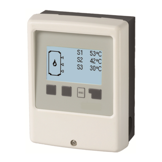
About the Controller The Thermostat Controller TC facilitates efficient use and function control of your solar or heating system possible while its hand- ling is intuitive. After every input step the suitable functions are matched to the keys and explained in a text above. In the menu 'measurement values and settings' are help text and graphics in addition to key words. -
Page 6: Hydraulic Variants
Hydraulic Variants The following illustrations should be regarded only as schematic representations of the respective hydraulic systems and do not claim to be complete. Under no circumstances should the controller replace any safety devices. Depend- ing on the specific application, additional system and safety components such as check valves, non-return valves, safety temperature limiters, scalding protectors, etc., may be required. -
Page 7: Electrical Connection
Electrical Connection Before working on the unit, switch off the power supply and secure it against being switched on again! Check that there is no power flowing! Electrical connections may only be made by a specialist and in compliance with the applicable regulations. -
Page 8: Installing The Temperature Sensors
Installing the Temperature Sensors The controller operates with Pt1000 temperature sensors which are accurate to 1 °C, ensuring optimal control of system func- tions. If desired, the sensor cables can be extended to a maximum of 30 m using a cable with a cross-section of at least 0.75 mm². -
Page 9: Commissioning Help
Commissioning help 1. Set language and time 2. Commissioning help / setup wizard a) select or b) skip. The setup wizard guides through the necessary basic settings in the cor- rect order. Each parameter is explained in the control display. Pressing the „esc“ key takes you back to the previous setting. b) With free commissioning the settings should be made in the following order: menu 10. -
Page 10: Heat Quantity
Heat quantity Display of the consumed heat quantity form the system in kWh. Graphic overview This results in a clear illustration of the data as a bar graph. Different time ranges are available for comparison. You can page through with the two left keys. Error Messages Display of the last 15 errors in the system with indication of date and time. -
Page 11: Pv Contact
Program 1 In this program only temperatures are sown in the display without thermostat switch. Programm 2 Thermostat is switched on, if the temperature at sensor S1 is below "Tset on" and is switched off again when "Tset off" is reached at sensor S1. -
Page 12: Protective Functions
5. Protective Functions The 'Protective functions‘ can be used by specialists to activate and set vari- ous protective functions. By no means does the controller replace the safety appliances on site! Seizing Protection If the anti-seizing protection is activated, the controller switches the heat pump and the mixer on/off at 12:00 noon for 5 seconds to prevent seizing of the pump/valve after long periods of inactivity. -
Page 13: Special Functions
6. Special Functions Used to set basic items and expanded functions. The settings in this menu should only be changed by a specialist. Program selection Here the hydraulic variation fitting to the respective use case is selected and set. The program selection normally occurs only once during the first entry into service by a specialist. An incorrect pro- gram selection may lead to unpredictable errors. -
Page 14: Menu Lock
If a message exists, the backlight does not switch off until the message has been scanned by the user. 7. Menu Lock Secure the controller against unintentional changing and compromise of basic functions. The menus listed below remain completely accessible despite the menu lock being activated, and can be used to make adjustments if necessary: 1. -
Page 15: Malfunctions/Maintenance
Malfunctions/Maintenance Replacing the Fuse Repairs and maintenance may only be performed by a specialist. Before working on the unit, switch off the power sup- ply and secure it against being switched on again! Check that there is no power flowing! Only use the supplied spare fuse or a fuse of the same design with the following specifications: 2 AT/250 VSOREL Art. - Page 16 Subject as a basic principle to errors and technical changes. Date and time of installation: Name of installation company: Space for notes: Your specialist dealer: Manufacturer: SOREL GmbH Mikroelektronik Reme-Str. 12 D - 58300 Wetter (Ruhr) +49 (0)2335 682 77 0 +49 (0)2335 682 77 10 info@sorel.de www.sorel.de...
Need help?
Do you have a question about the TC and is the answer not in the manual?
Questions and answers