
Related Manuals for Beckhoff ELX4154


Summary of Contents for Beckhoff ELX4154
- Page 1 Operating manual | EN ELX4154 Four channel analog output terminal, 0/4…20 mA, single-ended, 16 Bit, Ex i 2020-08-26 | Version: 1.0...
-
Page 3: Table Of Contents
Notes on the documentation...................... 5 Safety instructions .......................... 6 Documentation Issue Status...................... 7 Marking of ELX terminals ........................ 8 2 Product overview............................. 12 ELX4154 - Introduction ........................ 12 Technical data .......................... 13 Intended use ............................ 14 3 Mounting and wiring.......................... 15 Special conditions of use for ELX terminals .................. 15 Installation notes for ELX terminals .................... 15... - Page 4 Table of contents Version: 1.0 ELX4154...
-
Page 5: Foreword
EP1590927, EP1789857, EP1456722, EP2137893, DE102015105702 with corresponding applications or registrations in various other countries. ® EtherCAT is registered trademark and patented technology, licensed by Beckhoff Automation GmbH, Germany. Copyright © Beckhoff Automation GmbH & Co. KG, Germany. The reproduction, distribution and utilization of this document as well as the communication of its contents to others without express authorization are prohibited. -
Page 6: Safety Instructions
All the components are supplied in particular hardware and software configurations appropriate for the application. Modifications to hardware or software configurations other than those described in the documentation are not permitted, and nullify the liability of Beckhoff Automation GmbH & Co. KG. Personnel qualification This description is only intended for trained specialists in control, automation and drive engineering who are familiar with the applicable national standards. -
Page 7: Documentation Issue Status
Foreword Documentation Issue Status Version Comment • Contact assignment updated • Contact assignment updated • Technical data updated • First preliminary version ELX4154 Version: 1.0... -
Page 8: Marking Of Elx Terminals
• Beckhoff Traceability Number, or BTN for short (as a serial number it clearly identifies each terminal) Date code The date code is an eight-digit number given by Beckhoff and printed on the ELX terminal. The date code indicates the build version in the delivery state and thus identifies an entire production batch, but does not distinguish between the terminals in a batch. -
Page 9: Fig. 1 Elx2008-0000 With Date Code 2519Hmhm, Btn 0001F6Hd And Ex Marking
Foreword Beckhoff Traceability Number (BTN) In addition, each ELX terminal has a unique Beckhoff Traceability Number (BTN). Ex marking The Ex marking can be found at the top left on the terminal: II 3 (1) G Ex ec [ia Ga] IIC T4 Gc... -
Page 10: Fig. 2 Elx9560-0000 With Date Code 12150000, Btn 000B000 And Ex Marking
Foreword Fig. 2: ELX9560-0000 with date code 12150000, BTN 000b000 and Ex marking Version: 1.0 ELX4154... -
Page 11: Fig. 3 Elx9012 With Date Code 12174444, Btn 0000B0Si And Ex Marking
Foreword Fig. 3: ELX9012 with date code 12174444, BTN 0000b0si and Ex marking ELX4154 Version: 1.0... -
Page 12: Product Overview
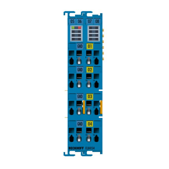
Fig. 4: ELX4154 - Four channel analog output terminal, 0/4…20 mA, single ended, 16 Bit, Ex i The ELX4154 analog output terminal is used for the direct connection of intrinsically safe field devices located in hazardous areas classified Zone 0/20 or 1/21. It can be used, for example, to control intrinsically safe controllers for control valves. -
Page 13: Technical Data
Product overview Technical data Technical data ELX4154-0000 Technology intrinsically safe sensors Number of outputs 4 (single ended) Connection technology 2-wire Nominal voltage 24 V Signal current 0/4…20 mA Load 400 Ω Resolution 16 bit (incl. sign) Conversion time typically 1 ms Supply voltage electronics via E-Bus (5 V... -
Page 14: Intended Use
The ELX components may only be used in accordance with the ATEX directive and the IECEx scheme! The ELX terminals extend the field of application of the Beckhoff bus terminal system with functions for integrating intrinsically safe field devices from hazardous areas. The intended field of application is data acquisition and control tasks in discrete and process engineering automation, taking into account explosion protection requirements. -
Page 15: Mounting And Wiring
Special conditions of use for ELX terminals WARNING Observe the special conditions of use for the intended use of Beckhoff ELX terminals in potentially explosive areas (ATEX directive 2014/34/EU)! • The certified components are to be installed in a suitable housing that guarantees an ingress protection of at least IP54 in accordance with EN 60079-0 and EN 60529! The prescribed environmental conditions... - Page 16 1 to 8 on the left above the respective terminal point as well as via the laser image. Observe any possible polarity dependency of connected intrinsically safe circuits! Version: 1.0 ELX4154...
-
Page 17: Arrangement Of Elx Terminals Within A Bus Terminal Block
• The last terminal of each ELX segment is to be covered by an ELX9012 bus end cover, unless two ELX9410 power supply terminals are installed in direct succession for continuing the same terminal seg- ment with standard Beckhoff EtherCAT terminals (e.g. EL/ES/EK)! Examples for the arrangement of ELX terminals Fig. 5: Valid arrangement of the ELX terminals (right terminal block). -
Page 18: Fig. 8 Valid Arrangement - Elx9410 In Front Of An Elx9560 Power Supply Terminal
Fig. 9: Invalid arrangement - missing ELX9560 power supply terminal. Fig. 10: Invalid arrangement - terminal that does not belong to the ELX series within the ELX terminal segment. Fig. 11: Invalid arrangement - second ELX9560 power supply terminal within the ELX terminal segment without an upstream ELX9410. Version: 1.0 ELX4154... -
Page 19: Fig. 12 Invalid Arrangement - Missing Elx9012 Bus End Cover
ELX9560 power supply terminal in accordance with the specified technical data. If required, an additional power supply terminal ELX9560 with an upstream ELX9410 connected (see mounting examples) must be installed or a completely new terminal block must be assembled. ELX4154 Version: 1.0... -
Page 20: Installation Position And Minimum Distances
• besides the bus terminal block: 20 mm (recommended) Fig. 13: Installation position and minimum distances WARNING Observe the minimum separation distances according to IEC 60079-14! Observe the prescribed minimum separation distances between intrinsically safe and non-intrinsically safe circuits according to IEC 60079-14. Version: 1.0 ELX4154... -
Page 21: Installation Of Elx Terminals On Mounting Rails
To mount the mounting rails with a height of 7.5 mm under the terminals and couplers, you should use flat mounting connections (e.g. countersunk screws or blind rivets). ELX4154 Version: 1.0... -
Page 22: Fig. 15 Disassembling Of Terminal
During the design of a bus terminal block, the pin assignment of the individual Bus Terminals must be taken account of, since some types (e.g. analog Bus Terminals or digital 4-channel Bus Termi- nals) do not or not fully loop through the power contacts. Version: 1.0 ELX4154... -
Page 23: Connection
Ultrasonically "bonded" (ultrasonically welded) conductors Ultrasonically “bonded" conductors It is also possible to connect the Standard and High Density Terminals with ultrasonically "bonded" (ultrasonically welded) conductors. In this case, please note the tables concerning the wire-size width below! ELX4154 Version: 1.0... -
Page 24: Wiring
Wire stripping length 8 ... 9 mm 8 ... 9 mm NOTE Maximum screwdriver width for ELX9560 Use a screwdriver with a maximum width of 2 mm to wire the ELX9560 power supply terminal. Wider screwdrivers can damage the terminal points. Version: 1.0 ELX4154... -
Page 25: Proper Line Connection
In any case, make sure that the galvanic isolation made by the ELX9560 between the 24 V Ex busbar (power contacts +24 V Ex and 0 V Ex) and other system potentials (if applicable also functional or protec- tive earths) is not removed. ELX4154 Version: 1.0... -
Page 26: Contact Assignment
Mounting and wiring 3.6.5 Contact assignment Fig. 19: ELX4154 - Contact assignment Terminal point Description Name not implemented not implemented not implemented not implemented ground ground ground ground Output 1 Output channel 1 Output 2 Output channel 2 Output 3 Output channel 3... - Page 27 State of the EtherCAT State Machine: SAFEOP = verification of the Sync flash Manager channels and the distributed clocks. Outputs remain in safe state State of the EtherCAT State Machine: OP = normal operating state; mailbox and process data communication is possible Error EtherCAT communication error ELX4154 Version: 1.0...
-
Page 28: Appendix
Beckhoff EtherCAT modules are intended for use with Beckhoff’s UL Listed EtherCAT Sys- tem only. Examination For cULus examination, the Beckhoff I/O System has only been investigated for risk of fire and electrical shock (in accordance with UL508 and CSA C22.2 No. 142). For devices with Ethernet connectors Not for connection to telecommunication circuits. -
Page 29: Fm Notice
Group A, B, C, D or in non-explosive areas! WARNING Consider the Control Drawing ELX documentation! When installing the I/O modules of the ELX series, be sure to read the Control Drawing ELX documentation, which is available for download on https://www.beckhoff.de/english/ download/ethercat.htm! ELX4154 Version: 1.0... -
Page 30: Support And Service
Beckhoff's branch offices and representatives Please contact your Beckhoff branch office or representative for local support and service on Beckhoff products! The addresses of Beckhoff's branch offices and representatives round the world can be found on her internet pages: http://www.beckhoff.com You will also find further documentation for Beckhoff components there. - Page 31 Fig. 3 ELX9012 with date code 12174444, BTN 0000b0si and Ex marking .......... Fig. 4 ELX4154 - Four channel analog output terminal, 0/4…20 mA, single ended, 16 Bit, Ex i... Fig. 5 Valid arrangement of the ELX terminals (right terminal block)............
- Page 33 More Information: www.beckhoff.com/ELX4154 Beckhoff Automation GmbH & Co. KG Hülshorstweg 20 33415 Verl Germany Phone: +49 5246 9630 info@beckhoff.com www.beckhoff.com...
Need help?
Do you have a question about the ELX4154 and is the answer not in the manual?
Questions and answers