
Related Manuals for Portwell WADE-8066


Summary of Contents for Portwell WADE-8066
- Page 1 WADE-8066 Mini-ITX Board User's Manual Version 1.0 Copyright © Portwell, Inc., 2008. All rights reserved. All other brand names are registered trademarks of their respective owners.
-
Page 2: Table Of Contents
Preface Table of Contents How to Use This Manual Chapter 1 System Overview.......................1-1 1.1 Introduction..........................1-1 1.2 Check List ............................. 1-1 1.3 Product Specification ........................1-2 1.3.1 Mechanical Drawing......................1-5 1.4 System Architecture ........................1-6 Chapter 2 Hardware Configuration ...................2-1 2.1 Jumper Setting .......................... -
Page 3: How To Use This Manual
Portwell may make supplement or change in the products described in this document at any time. Updates to this manual, technical clarification, and answers to frequently asked questions will be shown on the following web site : http://www.portwell.com.tw/. -
Page 4: Chapter 1 System Overview
Celeron M 550. The graphic media accelerator X3100 provides both fast video response time and high quality images via the two-channel memory architecture. WADE-8066 supports dual display by VGA, DVI, LVDS and TV-Out. With its display-enriched interface, WADE-8066 can support various multimedia devices and suitable for Medical, KIOSK, Digital Signage and other multiple display applications. -
Page 5: Product Specification
Watchdog Timer - Support WDT function through software programming for enable/disable and interval setting - Generate system reset On-board VGA - Intel GME965 Integrated GMA 3000 Graphics device - Intel DVMT 4.0 supports up to 384MB video memory WADE-8066 User’s Manual... - Page 6 Power Requirements: Configuration: System Configuration CPU Type Intel®Mobile Core 2 Duo T7500 2.2GHz(200*11) L2:4068K SBC BIOS Portwell.Inc WADE-8066 BIOS Rev.:R2.10.W1(12212007) Memory Apacer DDR2 512MB PC4300 (SAMSUNG K4T510830B-ZCD5) VGA Card Onboard Mobile Intel®965 Express Chipset VGA Driver Intel®965 Express Chipset Family Corporation Version...
- Page 7 1.32A Full Loading Full Loading Item Power ON Enter OS 10Min 30Min System+Device 3.92A 3.93A 3.91A 3.95A System+Device 2.99A 3.10A 3.12A Operating Temperature: 0°C ~ 55°C Storage Temperature: -20°C ~ 80°C Relative Humidity: 5% ~ 90%, non-condensing WADE-8066 User’s Manual...
-
Page 8: Mechanical Drawing
System Overview 1.3.1 Mechanical Drawing WADE-8066 User’s Manual... -
Page 9: System Architecture
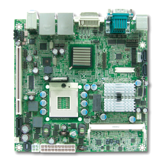
System Overview System Architecture All of details operating relations are shown in WADE-8066 series System Block Diagram. Merom CPU SIL1362 SDVO DVI-I SO-DIMM A DDR2 GME965 LVDS SO-DIMM B DDR2 TV-OUT HD AUDIO 82566MM HDA BUS GLCI Marvell USB 2.0 * 8... -
Page 10: Chapter 2 Hardware Configuration
( ). Jumper Setting In order to customize WADE-8066’s features for users, in the following sections, Short means covering a jumper cap over jumper pins; Open or N/C (Not Connected) means removing a jumper cap from jumper pins. Users can refer to Figure 2-1 and Figure 2-2 for the Jumper locations. - Page 11 Hardware Configuration Figure 2-2 WADE-8066 Bottom-side Connector Locations JP1: CMOS Normal / Clear Jumper Normal Clear Function 1-2 Short Clear CMOS Disable (Normal) 2-3 Short Clear CMOS Enable (Clear) WADE-8066 User’s Manual...
- Page 12 22 20 18 16 14 12 10 8 6 4 2 Function 5-6,9-11,10-12,15-17,16-18 Short RS-232 3-4,7-9,8-10,13-15,14-16,21-22 Short RS-422 1-2,7-9,8-10,19-20 Short RS-485 JP2, JP4, JP5: COM2(J2 Top) RS232/TTL Interface Selection RS-232 Mode: 1-2 Short 1-2,3-4,5-6,7-8,9-10,11-12,13-14,15-16 Short All Open TTL Mode: Open All Open 1-2,3-4,5-6,7-8,9-10,11-12,13-14,15-16 Short WADE-8066 User’s Manual...
- Page 13 3-5, 4-6 Short 12 V, Active low JP11: Auto power on jumper JP11 Function 1-2 Short System boots up automatically with jumper populated after PSU powered. 1-2 Open System requires power button pushed to boot up without jumper populated. WADE-8066 User’s Manual...
-
Page 14: Connector Allocation
System fan connector DDR2 SO-DIMM socket 1 CPU fan connector +12V CPU power connector ATX power connector Specified PCI Express x4 connector (Not support common PCI Express x1 cards) Compact flash card socket DDR2 SO-DIMM socket 2 WADE-8066 User’s Manual... - Page 15 Analog green Analog blue Analog horizontal sync Analog ground J2: COM1/COM2 Serial Port Connector -COM1 PIN No. Signal Description RS-232 RS-422 RS-485 DCD (Data Carrier Detect) DATA- RXD (Receive Data) DATA+ TXD (Transmit Data) DTR (Data Terminal Ready) WADE-8066 User’s Manual...
- Page 16 CTS (Clear to Send) RI (Ring Indicator) or +12V J4: Audio Jack PIN No. Signal Description 1 (Blue) Line In 2 (Green) Line Out1 3 (Pink) Mic1 J7: TV-out pin header PIN No. Signal Description Ground COMP/B WADE-8066 User’s Manual...
- Page 17 J9: Front I/O audio panel pin header PIN No. Signal Description Mic2-left Audio ground Mic2-right Line out2-right Line out2-left J12: 8-bit GPIO pin header 1 PIN No. Signal Description PIN No. Signal Description GPIO10 GPIO20 GPIO11 GPIO21 GPIO12 GPIO22 GPIO13 GPIO23 Ground WADE-8066 User’s Manual...
- Page 18 J15: 8-bit GPIO pin header 2 PIN No. Signal Description PIN No. Signal Description GPIO14 GPIO24 GPIO15 GPIO25 GPIO16 GPIO26 GPIO17 GPIO30 Ground J16: LVDS panel backlight unit connector PIN No. Signal Description Backlight enable Ground +12V WADE-8066 User’s Manual...
- Page 19 LVDS channel B data3- LVDS channel B clock+ LVDS channel B clock- LVDS DDC data * LVDS DDC clock * Ground Panel backlight brightness control Ground Ground Power depends on JP8 Power depends on JP8 Power depends on JP8 WADE-8066 User’s Manual 2-10...
- Page 20 Hardware Configuration * DDC: Display Data Channel. EDID support for flat panel display. WADE-8066 User’s Manual 2-11...
- Page 21 Power LED (-) Key lock (+) Key lock (-) HDD LED (+) +5V with 1k-ohm pull-up HDD LED (-) J23: Infrared transmission (IrDA) pin header PIN No. Signal Description IRRX Infrared Transmitter Input Ground IRTX Infrared Transmitter Output. WADE-8066 User’s Manual 2-12...
- Page 22 Hardware Configuration WADE-8066 User’s Manual 2-13...
- Page 23 Fan speed control (voltage control) Fan speed sense J28: ATX power connector PIN No. Signal Description PIN No. Signal Description +3.3V +3.3V Ground Ground Ground PWR_OK +5V stand by +12V +3.3V -12V Ground PS_ON# Ground Ground Ground WADE-8066 User’s Manual 2-14...
-
Page 24: Chapter 3 System Installation
(pin 1) of the CPU corresponds to the socket’s bevel end. Then press the CPU gently until it fits into place . If this operation is not easy or smooth, don’t do it forcibly. You need to check and rebuild the CPU pin uniformly. PIN 1 WADE-8066 User’s Manual... -
Page 25: Main Memory
4) Follow the steps of installing a CPU to change to another one or place handling bar to close the opened socket. Configuring System Bus WADE-8066 will automatically detect the CPU FSB 533/800MHz used. CPU speed of Intel Core 2 Duo Processor for Mobile and Celeron M can be detected automatically. Main Memory... - Page 26 To maintain system stability, don’t change any of DRAM parameters in BIOS setup to upgrade system performance without acquiring technical information. Memory frequency / CPU FSB synchronization WADE-8066 supports different memory frequencies depending on the CPU front side bus and the type of DDR2 SO-DIMM. CPU FSB...
-
Page 27: Installing The Single Board Computer
Step 1 : Check all jumpers setting on proper position Step 2 : Install and configure CPU and memory module on right position Step 3 : Place WADE-8066 into the dedicated position in the system Step 4 : Attach cables to existing peripheral devices and secure it WARNING Please ensure that SBC is properly inserted and fixed by mechanism. -
Page 28: Chipset Component Driver
3.3.1 Chipset Component Driver The chipset on WADE-8066 is a new chipset that a few old operating systems might not be able to recognize. To overcome this compatibility issue, for Windows Operating Systems such as Windows 2000 /XP / Server 2003, please install its INF before any of other Drivers are installed. -
Page 29: Intel Gigabit Ethernet Controller
3.3.3 Intel Gigabit Ethernet Controller Drivers Support Please find Intel 82566MM LAN1 driver in /Ethernet directory of WADE-8066 CD-title. The drivers support Windows 2000 /XP / Server 2003. LED Indicator (for LAN1 status) WADE-8066 provides two LED indicators to report Intel 82566MM Gigabit Ethernet interface status. -
Page 30: Audio Controller
System Installation LED Indicator (for LAN2 status) WADE-8066 provides two LED indicators to report Marvell 88E8053 Gigabit Ethernet interface status. Please refer to the table below as a quick reference guide. Operation of Ethernet Port 88E8053 Color Name of LED... -
Page 31: Raid Device
3.3.6 RAID Device Drivers Support Please find Intel ICH8M-E driver of WADE-8066 CD-title. The drivers support Vista / Vista x32 / Vista x64 / WindowXP System. Installing Serial ATA hard disks The WADE-8066 supports Serial ATA hard disk drives. For optimal performance, install identical drives of the same model and capacity when creating a disk array. -
Page 32: Clear Cmos Operation
WADE-8066 allows users to control WDT through dynamic software programming. The WDT starts counting when it is activated. It sends out a signal to system reset or to non-maskable interrupt (NMI), when time-out interval ends. - Page 33 System Installation WDT should never generate a system reset or NMI signal unless the system runs into troubles. WADE-8066 User’s Manual 3-10...
- Page 34 (inp(0x002F) & 0xF7) | ( Count-mode Register & 0x08)); // Specify Time-out Value outp(0x002E, 0xF6); outp(0x002F, Time-out Value Register // Disable WDT reset by keyboard/mouse interrupts outp(0x002E, 0xF7); outp(0x002F, 0x00); // Exit Extended Function Mode outp(0x002E, 0xAA); WADE-8066 User’s Manual 3-11...
-
Page 35: Gpio
2) 0x01~0xFF -- Value for counting down GPIO The WADE-8066 provides 16 input/output ports that can be individually configured to perform a simple basic I/O function. Users can configure each individual port to become an input or output port by programming register bit of I/O Selection. To invert port value, the setting of Inversion Register has to be made. - Page 36 I/O Selection. To invert port value, the setting of Inversion Register has to be made. Port values can be set to read or write through Data Register. WADE-8066 User’s Manual 3-13...
-
Page 37: Chapter 4 Bios Setup Information
Chapter 4 BIOS Setup Information WADE-8066 is equipped with the AWARD BIOS stored in Flash ROM. These BIOS has a built-in Setup program that allows users to modify the basic system configuration easily. This type of information is stored in CMOS RAM so that it is retained during power-off periods. -
Page 38: Main Menu
BIOS Setup Information Main Menu Once you enter WADE-8066 AWARD BIOS CMOS Setup Utility, a Main Menu is presented. The Main Menu allows user to select from eleven setup functions and two exit choices. Use arrow keys to switch among items and press <Enter> key to accept or bring up the sub-menu. -
Page 39: Standard Cmos Setup Menu
515072K ↑↓→←: Move Enter: Select +/-/PU/PD: Value F10: Save ESC: Exit F1: General Help F5: Previous Values F6: Fail-Safe Defaults F7: Optimized Defaults Note: Oblique items are base on memory capacity which user adopts on single board. WADE-8066 User’s Manual... -
Page 40: Ide Adaptors Setup Menu
To atuo-detect the HDD’s Cylinder 38309 size, head … on this Head channel Precomp Landing Zone 38308 Sector ↑↓→←: Move Enter: Select +/-/PU/PD: Value F10: Save ESC: Exit F1: General Help F5: Previous Values F6: Fail-Safe Defaults F7: Optimized Defaults WADE-8066 User’s Manual... - Page 41 Set the number of cylinders for hard disk Head Min=0, Max=255 Set the number of read/write heads Precomp Min=0, Max=65535 **** Warning: Setting a value of 65535 means no hard disk Landing zone Min=0, Max=65535 **** Sector Min=0, Max=255 Number of sectors per track WADE-8066 User’s Manual...
-
Page 42: Advanced Bios Features
Execute Disabled Bit [Enabled] Menu Level Virtualization Technology [Enabled] Core Multi-Processing [Enabled] CPU C1E Function Select ↑↓→←: Move Enter: Select +/-/PU/PD: Value F10: Save ESC: Exit F1: General Help F5: Previous Values F6: Fail-Safe Defaults F7: Optimized Defaults WADE-8066 User’s Manual... - Page 43 Select Hard Disk Boot Device Priority. Use < > or < > to select a device, then press <+> to move it up, or <-> to move it down the list. Press <ESC> to exit this menu. WADE-8066 User’s Manual...
- Page 44 Boot Up NumLock Status Select power on state for NumLock. The choice: Off, On. Gate A20 Option Fast-lets chipsets control GateA20 and Normal – a pin in the keyboard controller controls GateA20. Default is fast. The choice: Normal, Fast. WADE-8066 User’s Manual...
- Page 45 Select OS/2 only if you are running OS/2 operating system with greater than 64MB of RAM on the system. The choice: Non-OS2, OS2. Report No FDD for WIN 95 The choice: No, Yes. Small Logo (EPA) Show The choice: Enabled, Disabled. WADE-8066 User’s Manual...
-
Page 46: Advanced Chipset Features
↑↓→←: Move Enter: Select +/-/PU/PD: Value F10: Save ESC: Exit F1: General Help F5: Previous Values F6: Fail-Safe Defaults F7: Optimized Defaults System BIOS Cacheable. The choice: Enabled, Disabled. Memory Hole At 15-16M The choice: Enabled, Disabled. WADE-8066 User’s Manual 4-10... -
Page 47: Dvmt Mode
The choice: VBIOS Default, CRT, LVDS, CRT+LVDS, DVI, TV, CRT+DVI, CRT+TV. Panel Scaling The choice: Auto, On, Off. Panel Number The choice: 1, 2, 3, 4, 5, 6, 7, 8, 9, 10, 11, 12, 13, 14, 15, 16 ( WADE-8066 User’s Manual 4-11... -
Page 48: Integrated Peripherals
F7: Optimized Defaults IDE HDD Block Mode If IDE hard drive supports block mode select Enabled for automatic detection of the optimal number of block read/writes per sector the drive can support. The choice: Enabled, Disabled. WADE-8066 User’s Manual 4-12... - Page 49 DMA driver (Windows 95 OSR2 or a third-party IDE bus master driver). If your hard drive and system software both support Ultra DMA/33/66/100, select Auto to enable BIOS support. The choice: Auto, Disabled. WADE-8066 User’s Manual 4-13...
- Page 50 Low rate for receiving / High rate for transmitting Lo, Lo Low rate for receiving / Low rate for transmitting IR Transmission Delay This option will be available when IR is enabled. The choice: Enabled, Disabled. WADE-8066 User’s Manual 4-14...
- Page 51 Enter: Select +/-/PU/PD: Value F10: Save ESC: Exit F1: General Help F5: Previous Values F6: Fail-Safe Defaults F7: Optimized Defaults USB 1.0 Controller [Enabled] or [Disabled] Universal host controller interface for universal serial bus. The choice: Enabled, Disabled. WADE-8066 User’s Manual 4-15...
- Page 52 The choice: High Speed, Full/Low Speed. USB Keyboard/Mouse Function [Enabled] or [Disabled] Legacy support of USB keyboard or mouse. The choice: Disabled, Enabled. USB Storage Function [Enabled] or [Disabled] Legacy support of USB Mass Storage. USB) WADE-8066 User’s Manual 4-16...
-
Page 53: Power Management Setup
F7: Optimized Defaults ACPI Function This item allows you to enable/disable the Advanced Configuration and Power Management (ACPI). The choice: Enabled, Disabled. ACPI Suspend Type To decide which ACPI suspend mode to use. The choice: S3 (STR) only. WADE-8066 User’s Manual 4-17... - Page 54 The choice: Yes, No. Soft-Off by PWR-BTTN This item allows users to set the time to remove the power after the power button is pressed. The choice: Instant-Off, Delay 4 Sec. Wake-Up By PCI card The choice: Disabled, Enabled. WADE-8066 User’s Manual 4-18...
- Page 55 FDD, COM, LPT Port This item is to configure floppy device, COM ports, and parallel port being monitored by system so as to keep system out of suspend mode if the associated device is busy. The choice: Enabled, Disabled. WADE-8066 User’s Manual 4-19...
-
Page 56: Pnp/Pci Configurations
Default is Disabled. Select Enabled to reset Extended System Configuration Data (ESCD) when you exit Setup if you have installed a new add-on and the system reconfiguration has caused such a serious conflict that the OS cannot boot. The choice: Enabled, Disabled. WADE-8066 User’s Manual 4-20... - Page 57 Legacy ISA for devices compliant with the original PC AT bus specification, PCI PnP for devices compliant with the plug and play standard whether designed for PCI bus architecture. The choice: Enabled, Disabled. Maximum Payload Size. Default 128. WADE-8066 User’s Manual 4-21...
-
Page 58: Pc Health Status
The choices : Disabled, 50 /122 , 53 /127 , 56 /133 , 60 /140 , 63 /145 , 66 /151 , 70 /158 . Smart System / CPU Fan Temp. The choices : Disabled, 40 / 104 , 45 / 113 , 50 /122 . Smart Fan Tolerance Value The choices: 0~5. WADE-8066 User’s Manual 4-22... -
Page 59: Frequency/Voltage Control
The choice: Enabled, Disabled. Spread Spectrum This item allows user to enable/disable the spread spectrum modulate. The choice: Enabled, Disabled. CPU Host/ SRC/ PCI Clock The choice: Default, 100/100/33MHz, 133/100/33 MHz, 166/100/33 MHz, 200/100/33MHz, 266/100/33 MHz, 333/100/33 MHz. WADE-8066 User’s Manual 4-23... -
Page 60: Default Menu
To disable a password, just press <Enter> when prompted to enter the password. A message will confirm the password will be disabled. Once the password is disabled, the system will reboot and Setup can be entered freely. WADE-8066 User’s Manual 4-24... -
Page 61: Exiting Selection
Pressing <Enter> on this item asks for confirmation: Quit Without Saving (Y/N)? N This allows user to exit Setup without storing in CMOS any change. The previous selections remain in effect. This exits the Setup utility and restarts your computer. WADE-8066 User’s Manual 4-25... -
Page 62: Chapter 5 Troubleshooting
Chapter 5 Troubleshooting This chapter provides a few useful tips to quickly get WADE-8066 running with success. As basic hardware installation has been addressed in Chapter 2, this chapter will primarily focus on system integration issues, in terms of BIOS setting, and OS diagnostics. -
Page 63: Bios Setting
BIOS setting back to the initial factory configuration. It is recommended to do this so you can be sure the system is running with the BIOS setting that Portwell has highly endorsed. As a matter of fact, users can load the default BIOS setting any time when system appears to be unstable in boot up sequence. - Page 64 ACPI Controller IRQ #10 USB 1.0/1.1 UHCI Controller, Multimedia Device IRQ #11 Network Controller IRQ #12 SMBus , USB 1.0/1.1 UHCI, USB 2.0 EHCI Controller IRQ #13 PS/2 mouse IRQ #14 Data Processor IRQ #15 Primary IDE Controller WADE-8066 User’s Manual...
-
Page 65: Ordering Setting
If IRQ resource is not enough, please disable some devices listed above to release further IRQ numbers. Ordering Setting PEP-581 582R One/Two slots PCI riser card PEP-581R PEP-582R PEP-592R One PCI and one PCI-E x4 slot riser card PEP-592R B9970540 1U active heatsink WADE-8066 User’s Manual... -
Page 66: Faq
Question: How do I connect my keyboard and mouse, as there is only one connector? Answer: Users may always adopt PS/2 keyboard and mouse over the PS/2 interface, J3 on WADE-8066. Information & Support Question: Intel GME965 series Chipset supports Dual Channel Mode, but how can I enable this function? Answer: you don’t have to change any setting. - Page 67 22 20 18 16 14 12 10 8 6 4 2 Function 5-6,9-11,10-12,15-17,16-18 Short RS-232 3-4,7-9,8-10,13-15,14-16,21-22 Short RS-422 1-2,7-9,8-10,19-20 Short RS-485 JP2, JP4, JP5: COM2(J2 Top) RS232/TTL Interface Selection RS-232 Mode: 1-2 Short 1-2,3-4,5-6,7-8,9-10,11-12,13-14,15-16 Short All Open WADE-8066 User’s Manual...
- Page 68 Please visit our technical web site at http://www.portwell.com.tw For additional technical information, which is not covered in this manual, you can mail to tsd@mail.portwell.com.tw or you can also send mail to our sales, they wull be very delighted to forward them to us. WADE-8066 User’s Manual...
- Page 69 Appendix A System Memory Address Map Each On-board device in the system is assigned a set of memory addresses, which also can be identical of the device. The following table lists the system memory address used for your reference. Memory Area Size Device Description 0000-003F...
- Page 70 Appendix B Interrupt Request Lines (IRQ) Peripheral devices can use interrupt request lines to notify CPU for the service required. The following table shows the IRQ used by the devices on board. IRQ# Current Use Default Use IRQ 0 System ROM System Timer IRQ 1 System ROM...
Need help?
Do you have a question about the WADE-8066 and is the answer not in the manual?
Questions and answers