Advertisement
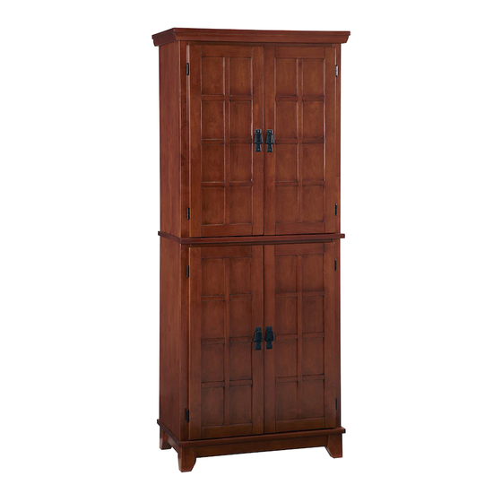
Pantry
IMPORTANT NOTE
Carefully remove all the parts from the carton and put
them individually on a soft cloth to prevent scratches
or other damage occurring to the parts.
We have taken great care in the design of this
product and request that you carefully and strictly
follow our assembly instructions to ensure a
completed product as it was designed.
Part List
A.
Top
1 Pc.
B.
Front Stretcher
1 Pc.
C.
Shelf
4 Pcs.
D.
Bottom
1 Pc.
N.
Top
1 Pc.
O.
Front Stretcher
1 Pc.
Hardware List
Hex Wrench
1 Pc.
Small Hex Wrench
1 Pc.
Tools required for assembly : Phillips screwdriver
E.
F.
Side Panel
Side Panel
1 Pc.
1 Pc.
P.
Q.
Side Panel
Side Panel
1 Pc.
1 Pc.
M3.5x16
Cam Lock Screw
Wood Screw
28 Pcs. (+1 extra)
for Back Panel
16 Pcs. (+1 extra)
Lock Screw
Adjustable Pin
28 Pcs. (+1 extra)
16 Pcs. (+1 extra)
G.
H.
Door
Door
1 Pc.
1 Pc.
K.
L.
Leg Frame
Leg Frame
1 Pc.
1 Pc.
R.
S.
Door
Door
1 Pc.
1 Pc.
M6x35
Head Cap Bolt
4 Pcs.(+1 extra)
Flat Washer
4 Pcs. (+1 extra)
Tools recommended for assembly : Level
I.
J.
Back Panel
Back Upright
2 Pcs.
1 Pc.
M.
Back Stretcher
4 Pcs.
U.
T.
Back Upright
Back Panel
1 Pc.
2 Pcs.
Spring Washer
4 Pcs. (+1 extra)
Knob
4 Pcs.
M4x15
Machine Screw
8 Pcs.
Advertisement
Table of Contents

Related Manuals for Homestyles Pantry 5180-64


Summary of Contents for Homestyles Pantry 5180-64
- Page 1 Pantry IMPORTANT NOTE Carefully remove all the parts from the carton and put them individually on a soft cloth to prevent scratches or other damage occurring to the parts. We have taken great care in the design of this product and request that you carefully and strictly follow our assembly instructions to ensure a completed product as it was designed.
- Page 2 Assembly Instructions 2 IMPORTANT * Please keep Hex Wrench in a safe place as you may need to tighten up the Head Cap Bolts in the future. * Do not tighten up all the head cap bolts and screws until each part is properly assembled. * Use a soft cloth between these parts and the fl...
- Page 3 Assembly Instructions 3/5 STEP 2 Cam Lock Attach Back Stretcher (M) to Side Panel (F) with Cam Lock. Attach Back Upright (J) to Back Stretcher (M). Slide Back Panels (I) to the unit. Attach Back Stretcher (M) to unit with Cam Lock. Attach Front Stretcher (B) to unit with Cam Lock.
- Page 4 Assembly Instructions 4/5 Cam Lock STEP 5 Attach Back Stretcher (M) to Side Panel (Q) with Cam Lock. Attach Back Upright (U) to Back Stretcher (M). Slide Back Panels (T) to the unit. Attach Back Stretcher (M) to unit with Cam Lock.
- Page 5 Assembly Instructions 5 /5 STEP 8 Insert Adjustable Pins into side panels at desired location. Place Shelves (C) into position. Attach Doors (G), (H), (R) and (S) to the side panels by sliding the door lift hinges into the side panel lift hinges. (See Figure 4) Attach Pull Handles to Door (G), (H), (R) and (S) with Machine Screws.
Need help?
Do you have a question about the Pantry 5180-64 and is the answer not in the manual?
Questions and answers