Advertisement
Quick Links
POSICONTROL
Signal converters & interfaces
IF55 ROT EP • IF55 LIN EP
Series
Complete documentation and EDS file
available for download at www.lika.biz
Warning: devices having order code ending with "/Sxxx" may have mechanical and electrical characteristics different from standard and be supplied with additional documentation for special connections (Technical Info).
Attenzione: i dispositivi con codice di ordinazione finale "/Sxxx" possono avere caratteristiche meccaniche ed elettriche diverse dallo standard ed essere provvisti di documentazione aggiuntiva per cablaggi speciali (Technical info).
Achtung: Geräte, deren Bestellschlüssel mit der Kennung /Sxxx enden, können in ihren mech. und elektr. Eigenschaften vom Standard abweichen. Diese werden daher mit einer ergänzenden Dokumentation ausgeliefert (Technical info).
Atención: los dispositivos con código de pedido acabado en "/Sxxx" pueden tener características mecánicas y eléctricas diferentes a las básicas y documentación adicional relativa a conexiones especiales (Technical Info).
Attention: les dispositifs avec code de commande terminant en "/Sxxx" peuvent avoir des caractéristiques mécaniques et électriques différentes du standard et documentation additionnelle pour les câblages spéciaux (Technical info).
EN
Mounting instructions
Installation on panel
Tighten the flange 2 using four M3 x 8 min. cylinder head screws 1. Max.
tightening torque: 1.1 Nm.
Installation with DIN rail clip
Loosen the screws 6 and separate the connection cap 5 from the flange 2; pay
careful attention to the inside electronic circuits and wirings.
drill a Ø 4.5 mm hole A in the flange 2; use the notch to guide the drill bit;
remove the scrap material after drilling;
mount the DIN TS35 clip 3 on the back of the flange 2 and fix it using the
provided M4 x 8 screw 4;
replace the cap 5 and fix it by means of the screws 6.
ES
Instrucciones de montaje
Montaje en panel
Fijar firmemente la brida 2 mediante los cuatro tornillos 1 M3 x 8 mm min.
de cabeza cilíndrica. Par de apriete máx.: 1.1 Nm.
Montaje en carril DIN mediante clip
Aflojar los dos tornillos 6 para separar la tapa de conexión 5 de la brida 2;
prestar mucha atención a los circuitos y conexiones eléctricas internas;
taladrar un agujero A Ø 4.5 mm en la brida 2; utilizar el orificio piloto para
guiar la broca; eliminar los residuos después de taladrar;
colocar el clip DIN TS35 3 detrás de la brida 2 y fijarlo mediante el tornillo M4
x 8 4;
fijar la tapa 5 mediante los tornillos 6.
POWER SUPPLY
Description
Pin
M12 4-pin
Male, A coding
+10Vdc
1
+30Vdc
n.c.
2
0Vdc
3
n.c.
4
PORT 1, PORT 2
Description
Pin
M12 4-pin
Female, D coding
Tx Data +
1
Rx Data +
2
Tx Data -
3
Rx Data -
4
IT
Installazione su pannello
Avvitare la flangia 2 con quattro viti 1 a testa cilindrica tipo M3 x 8 min.
Coppia di fissaggio max.: 1.1 Nm.
Installazione con clip per rotaia DIN
Svitare le viti 6 per separare il coperchio di connessione 5 dalla flangia 2
prestando attenzione ai circuiti e collegamenti interni;
fare un foro Ø 4.5 mm A in corrispondenza dell'invito A nella flangia 2;
rimuovere gli sfridi;
montare la clip DIN TS35 3 sul retro della flangia 2 e fissarla mediante la vite
M4 x 8 4 in dotazione;
ripristinare il coperchio 5 fissandolo con le viti 6.
FR
Montage sur panneau
Visser la bride 2 au moyen des quatre vis 1 type M3 x 8 min. à tête
cylindrique. Couple de serrage max.: 1.1 Nm.
Montage sur rail DIN avec clip
Dévisser les vis 6 pour séparer le couvercle de connexion 5 de la bride 2; portez
attention aux circuits électriques et aux branchements internes ;
percer un trou Ø 4.5 mm A dans la bride 2 ; utiliser le point de perçage marqué
à l'intérieur de la bride 2 pour ne pas glisser; enlever les débris;
installer le clip DIN TS35 3 derrière la bride 2 et le fixer au moyen de la vis M4 x
8 4 fournie;
monter le couvercle 5 et le fixer au moyen des vis 6.
Installation on panel
SSI connection
Description Pin
M12 8-pin
Female, A coding
0Vdc
1
+Vdc *
2
Clock IN +
3
Clock IN -
4
Data OUT +
5
Data OUT -
6
n.c.
7
n.c.
8
n.c. = not connected
Installation has to be carried out with power supply disconnected.
L'installazione deve essere eseguita in assenza di tensione.
Der Anschluss darf nur bei ausgeschalteter Versorgungsspannung erfolgen.
La instalación sólo debe ser efectuada en ausencia total de tensión.
Le montage du dispositif doit être effectué en absence totale de tension.
Istruzioni di montaggio
Instructions de montage
*
POWER SUPPLY DIP switch selects the power
supply voltage level to be provided to the connected
encoder. Set it to UP position to provide +10Vdc
+30Vdc power supply voltage level (default); set it to DOWN
position to set +5Vdc ±5% power supply voltage level.
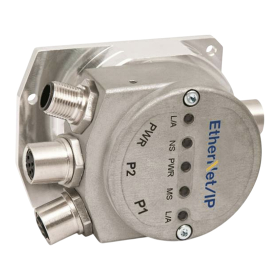
100 Mbps, full-duplex Ethernet network. EtherNet/IP networks
can be configured in almost any topology in the same structure.
Cables and connectors comply with the Ethernet specifications.
The maximum segment length for electrical data transmission
with copper cables between two nodes is 100 m / 328 ft. The
unit can be identified in the network through the MAC address
(10 B9 FEh + manufacturer consecutive number) and the IP
address (see on the right). PORT 1 and PORT 2 are
interchangeable. EtherNet/IP network needs no line termination.
DE
Montagehinweise
Montage auf Fronttafel
Flansch 2 mit vier M3 x 8 Schrauben 1 befestigen. Max. Anschraubmoment:
1.1 Nm.
Montage auf DIN Schiene
Schrauben 6 lösen und die Anschlusshaube 5 vom Flansch 2 vorsichtig
entfernen. Interne Leiterplatte und Anschlusskabel dabei berücksichtigen;
an der vorgegebene Position A am Flansch 2 ein Befestigungsloch mit Ø 4.5
mm bohren;
DIN TS35 Hutschienenklemme 3 auf Flansch 2 mit der beigelieferten M4 x 8
Schraube 4 befestigen;
Anschlusshaube 5 wider mit Schrauben 6 anschrauben.
WARNING
Please check and set the power supply voltage to be
provided to the connected encoder!
ATTENZIONE
Verificare e impostare la tensione di alimentazione da
fornire all'encoder collegato!
Installation with DIN rail clip
DIP A is used to set the last byte
of the hardware IP address. It
can further enable the software
IP address and DHCP protocol.
To access DIP A, remove the
connection cap 5. Loosen the two
M3 screws 6 (see the picture
above). Be careful with the internal
connector. Always replace the
connection cap 5 at the end of the
operation.
Take
care
in
re-
connecting the internal connector.
Tighten the screws 6 using a
tightening torque of approx. 2.5
Nm. Check that the flange 2 and
the connection cap 5 are at the
same potential before replacing
the connection cap!
DIP A = EtherNet/IP Node ID
DIP A (default) = 00000000 = software setting enabled
Default software node ID = 192.168.1.10
ON = 1, OFF = 0
Advertisement

Related Manuals for Lika POSICONTROL IF55 ROT EP Series


Summary of Contents for Lika POSICONTROL IF55 ROT EP Series
- Page 1 Series Complete documentation and EDS file available for download at www.lika.biz Warning: devices having order code ending with "/Sxxx" may have mechanical and electrical characteristics different from standard and be supplied with additional documentation for special connections (Technical Info). Attenzione: i dispositivi con codice di ordinazione finale “/Sxxx” possono avere caratteristiche meccaniche ed elettriche diverse dallo standard ed essere provvisti di documentazione aggiuntiva per cablaggi speciali (Technical info).
- Page 2 ● sécurité fondamentales prévues par le constructeur ou bien requêtes pour l'usage prévu du dispositif; la Société Lika Electronic nie toute responsabilité pour tout dommage ou blessure que l'utilisateur peut encourir à la suite de la non- ● Order code (example) observance des normes de sécurité.
Need help?
Do you have a question about the POSICONTROL IF55 ROT EP Series and is the answer not in the manual?
Questions and answers