Table of Contents
Advertisement
Quick Links
Electrical interface
CPX-CTEL-2-M12-5POL-LK
Brief description
Translation of the original instructions
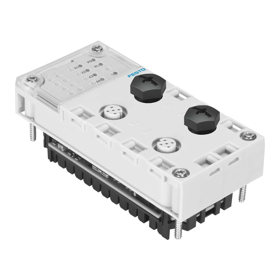
Electrical interface CPX-CTEL-2-M12-5POL-LK
For all available product documentation è www.festo.com/pk
1
Intended use
The module described in this document provides 2 outward interfaces to connect
devices with IO-Link interface (devices).
The module is intended for use in an industrial environment. Outside of industrial
environments, e.g. in commercial and mixed-residential areas, actions to suppress
interference may have to be taken.
The module is intended exclusively for use in CPX terminals from Festo for installa
tion in machines or automated systems and may be used only in the following
ways:
– in perfect technical condition
– in original status without unauthorised modifications, except for the adapta
tions described in this documentation
– within the limits of the product defined through the technical data.
®
IO-Link
is a registered trademark of its respective trademark holder in
certain countries.
2
Security
This documentation is directed exclusively toward technicians trained in control
and automation technology.
You can find detailed information in the description for the module
(P.BE-CPX-CTEL-2-M12-5POL-LK-...) as well as in the CPX system
description (P.BE-CPX-SYS-...).
Warning
Electric shock
Injury to people, damage to the machine and system
• For the electrical power supply, use only PELV circuits in accordance with
IEC 60204-1 (Protective Extra-Low Voltage, PELV).
• Observe the general requirements of IEC 60204-1 for PELV circuits.
• Use only voltage sources that guarantee a reliable electrical disconnection of
operating and load voltage in accordance with IEC 60204-1.
• Always connect all circuits for operating and load voltage supplies U
U
and U
.
VAL
OUT
Note
Electrostatically sensitive devices
• Do not touch any components.
• Observe the handling specifications for electrostatically sensitive
devices.
Note
• Take into account the specifications and notes in the description of the mod
ule and mounting instructions of the components.
• Commission the module only if fully mounted and wired.
Festo SE & Co.
KG Ruiter Straße
82 73734
Esslingen
+49 711 347-0
Germany
www.festo.com
8101617
2018-11a
[8101619]
. . . . . . . . . . . . . . . . . . . . . .
English
,
EL/SEN
3
Connections and displays
5
4
1
Rating plate
2
CPX-specific LEDs
3
1)
X3 and X4
1) Equip with protective cap (without function)
Fig. 1
3.1 Interfaces
Port
Pin
Allocation
1
24 V U
2
24 V U
3
0 V U
EL/SEN
4
C/Q
5
0 V U
VAL/OUT
M12 socket, 5-pin
Fig. 2
3.2 LED indicators
Status LEDs for port 1 and 2
1)
X1 ... X2
Status port 1 and 2
(green/red)
Connection status OK, device
error, configuration error or
compatibility error
1) Detailed information (è description for the module P.BE-CPX-CTE L-2-M12-5POL-LK-...)
2) Detailed information (è CPX system description P.BE-CPX-SYS-...)
Fig. 3
4
Mounting and installation
Warning
Electric shock
Injury to people, damage to the machine and system
• Switch off the power supply before mounting or dismantling the module
(danger of malfunctions or damage).
The module is mounted in an interlinking block of the CPX terminal.
1
Screws,
tightening torque: 0.9 ... 1.1 Nm
2
Module
Fig. 4
4.1 Dismantling
• Unscrew screws and carefully lift off the module.
Note
Material damage due to incorrect mounting
• Select screws suited to the material of the interlocking block:
– plastic: Thread-cutting tapping screws
– metal: Screws with metric thread.
If an individual module without CPX terminal is ordered, both screw types are
included.
1
2
3
4
2)
Port 1 and port 2
5
Status LEDs for port 1 and port 2
2) Connector socket: M12, A-coded, 5-pin
Function
Power supply (PS)
EL/SEN
Load voltage supply (PL)
VAL/OUT
Power supply (PS)
Communication C/Q
Load voltage supply (PL)
2)
CPX-specific LEDs
PS (green)
Operating voltage supply (Power
System)
PL (green)
Load voltage supply (Power Load)
(red)
CPX peripheral error
1
2
3
3
Interlinking block with contact rails
Advertisement
Table of Contents

Related Manuals for Festo CPX-CTEL-2-M12-5POL-LK


Summary of Contents for Festo CPX-CTEL-2-M12-5POL-LK
- Page 1 Status LEDs for port 1 and 2 CPX-specific LEDs interference may have to be taken. The module is intended exclusively for use in CPX terminals from Festo for installa X1 … X2 Status port 1 and 2 PS (green)
- Page 2 Wall and H-rail mounting SG 1 1) Observe that connected devices may only satisfy a lower degree of protection or smaller temperature range, etc. 2) Cover caps from Festo, type ISK-M12, for ports X3 and X4, included in delivery. Fig. 7...
Need help?
Do you have a question about the CPX-CTEL-2-M12-5POL-LK and is the answer not in the manual?
Questions and answers