Bentone B 55 Series Installation And Maintenance Instruction
Hide thumbs
Also See for B 55 Series:
- Installation and maintenance instructions manual (32 pages) ,
- Installation and maintenance instruction (44 pages) ,
- Installation and maintenance instruction (52 pages)

Related Manuals for Bentone B 55 Series


Summary of Contents for Bentone B 55 Series
- Page 1 178 072 66-1 2019-09-26 Providing sustainable energy solutions worldwide Installation- and maintenance instruction B 55, B65 Original translation of Installation- and maintenance instruction...
- Page 2 Beispiel Manuels dans d'autres langues. www.bentone.com\download ou scannez le code QR Saisir le numéro d'article du brûleur sur votre plaque signalétique (consultez l'illustration) et sélectionnez la langue. Bentone...
-
Page 3: Table Of Contents
6.3 Replacing the damper motor _______________________ 25 6.4 Replacement of oil pump __________________________ 26 6.5 Replacement of electrical components ______________ 27 6.6 Check oil line seals _______________________________ 27 6.10 Vibration ________________________________________ 28 6.11 Damper motor 2-Stage ___________________________ 29 6.12 Damper motor 3-Stage ___________________________ 30 Bentone... -
Page 4: General Information
• Burner pipes, fan wheels and air dampers may contain sharp edges. • The surface temperature of the burner’s components can exceed 60 °C. • Caution: The burner has moving parts, and there is risk of crushing injuries. 165 105 01 Bentone... - Page 5 - fi tting and installation work has been completed and approved - electrical installation has been correctly performed - fl ue gas ducts and combustion air ducts are not blocked - all actuators and control and safety devices are in working order and correctly set Bentone...
- Page 6 Delivery check • Make sure everything is delivered and the goods have not been damaged during transit. • If something is wrong with a delivery, report it to the supplier. • Transport damage must be reported to the shipping company. Bentone...
-
Page 7: Technical Data
Type Motor supply Main supply Sound 230/400V 3,1/1,8A 230V 0,38A 50Hz 89 dBA ± 0,5 dBA B 55 230/400V 5,9/3,4A 230V 0,38A 50Hz 89 dBA ± 0,5 dBA B 65 Max operating current, see data plate 165 205 32 Bentone... -
Page 8: Working Field B 55-2
2.2 Working field B 55-2 13,0-67,5 kg/h 155-800 kW B 55-2R B 55-2/-2H 2.3 Working field B 55-3R 13,0-64,0 kg/h 155-760 kW 2.4 Working field B 65-2 22,0-99,5 kg/h 260-1180 kW 2.5 Working field B 65-3R 24,0-99,0 kg/h 285-1170 kW Bentone... -
Page 9: Adjusting The Ignition Electrodes And Brake Plate
10 bar (8-25 bar) depending on pump model 2.8 Burner installation 2.8.1 Hole patten Make sure the hole pattern on the boiler is designed for burner flange. Combustion device B 55 ø (155) 165 ø (226) 254-300 B 65 ø (155) 205 ø (226) 254-300 Bentone... -
Page 10: Nozzle Table
89,36 1060 93,70 1111 97,88 1161 101,85 1208 1039 26,00 96,81 1148 101,50 1204 1035 106,04 1258 1081 110,33 1308 1168 The table applies to oil with a viscosity of 4.4 mm /s at a density of 830 kg/m Bentone... - Page 11 1057 1267 1089 24,00 1254 1078 1297 1116 1341 1153 1382 1188 26,00 1359 1168 1406 1209 1453 1249 1497 1287 The table applies to oil with a viscosity of 4.4 mm /s at a density of 830 kg/m Bentone...
-
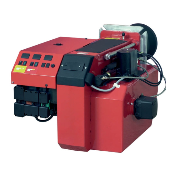
Page 12: Description B 55/B 65
Indicating lamp Stage 2 Nozzle adjustment fixed Nozzle assembly Switch l-ll Scale, nozzle assembly Ignition electrodes Indicating lamp Stage 1 Solenoid valve bloc Stage 2 Electric panel Switch 0-l Solenoid valves Damper motor Motor Connecting pipe Cover, inspection glass Bentone... - Page 13 Damper motor Scale, Nozzle assembly Air intake Fan wheel Solenoid valve bloc Stage 3 Solenoid valve bloc Stage 2 Thermal overload protection Hydraulic hose Connecting pipe Contactor Solenoid valve Control box Adjustment device, Nozzle Front plate, relay base assembly Bentone...
-
Page 14: General Instructions
The system must be fine-tuned at start-up. The temperature in the chimney must be at least 60 °C at 0.5 m down in the chimney to prevent condensation. 165 205 33 Bentone... -
Page 15: Installation
4. Installation 4.1 Handling and lifting instruktion Option The lifting aid we used here are available as spare parts, Figure 1. fi gure 1 Bentone... -
Page 16: Acceptance Inspection
• The connection should be made in accordance with the wiring diagram. • Fuse rating is as required If any electrical connection is used other than that recommended by Bentone, there may be a danger of damage to property and personal injury. -
Page 17: Mount The Burner On The Boiler
Once the burner has been installed and commissioned, the seals of the various coupling elements should be checked (A). When a leak is detected, it is usually suffi cient to tighten the coupling element that is leaking. 165 105 61 Bentone... -
Page 18: Basic Settings
Stage 2 and Stage 3, respectively. The positions of MV 2 and MV 3 are determined by the boiler characteristics when switching between stages, but for a basic setting the cams (MV2 and MV3) should be placed in the middle. 165 205 35 Bentone... - Page 19 See under Basic settings Note that it is simply a matter of a basic setting that should be adjusted retrospectively once the burner has started. A flue gas analysis and soot quantity measurement must be carried out when fine-tuning the burner. Bentone...
-
Page 20: Set Values For Nozzle Assembly B55
5.2 Set values for nozzle assembly B55 5.4 Set values for air damper B55 5.3 Set values for nozzle assembly B65 5.5 Set values for air damper B65 1000 1200 Bentone... -
Page 21: Nozzle Assembly Regulation - Fixed Brake Plate
Adjust to the desired position on the scale (A) using the set screw (D) (turning anti-clockwise reduces the pressure drop and moves the brake plate outwards). If pulsation occurs, the pressure drop across the brake plate can be alte-red until pulsation stops. Bentone... -
Page 22: Hydraulic Air Adjustment
(3.6, 3.7). Read the damper angle for each of the power stages This must then be used when the settings are made in the burner’s control system (se punkt 3.3) Check the air settings by conducting a flue gas analysis. Bentone... -
Page 23: Maintenance
Close the boiler / spectacle fl ange. Turn on the mains power. Check combustion*. When soiled, always replace nozzles with new nozzles. Note: When servicing/replacing components that affect combustion, an analysis and soot test must be carried out on the installation 165 205 36 Bentone... -
Page 24: Servicing Air Dampers
Slide the burner together and secure it with the nuts (E). Connect the Eurostecker connectors and turn on the main power switch. Check combustion*. Note: When servicing/replacing components that affect combustion, an analysis and soot test must be carried out on the installation Bentone... -
Page 25: Replacing The Damper Motor
Connect the Eurostecker connectors and turn on the main power switch. Check combustion.* When resetting dampers, ensure that they do not engage in the close damper position. If dampers do engage, the automatic control unit will report an error message. Bentone... -
Page 26: Replacement Of Oil Pump
Use caution when operating the burner, surfaces may be hot. When servicing oil bearing components, check the oil density when the burner is commissioned after servicing. Note: When servicing/replacing components that affect combustion, an analysis and soot test must be carried out on the installation Bentone... -
Page 27: Replacement Of Electrical Components
When a leak is detected, it is usually suffi cient to tighten the coupling element that is leaking. Använd Loctite 5188 på gängade oljeledningar Note: When servicing/replacing components that affect combustion, an analysis and soot test must be carried out on the installation Bentone... -
Page 28: Vibration
Maximum vibration level are 5,0 mm/s • Check all bolts and nuts for correct torque • Check fan wheel for damage and contamination. Change when dirty/ unbalanced • Check motor bearings. If worn change motor/bearings Use lid screw hole for sensor mounting Bentone... -
Page 29: Damper Motor 2-Stage
Solenoid valve Stage 2 (black) Stage 2 (red) Stage 1 (orange) Closed damper (blue) Releasing button N.B. The upper position is the standard position 165 205 39 Bentone... -
Page 30: Damper Motor 3-Stage
* Increase the air volume: Turn orange cam towards 90°. Solenoid valve Stage 3 (green) Solenoid valve Stage 2 (black) Stage 3 (red) Stage 2 (orange) Stage 1 (blue) Releasing button N.B. The upper position is the standard position 165 205 40 Bentone... -
Page 31: Instructions Pump Rsa 95 & 125
Replace the oil fiter on the oil pump as follows.. • Close the oil valves. • Unscrew the cover (4 x 5 mm Allen screws). • Replace the oil filter. • Replace the cover gasket. • Refit the cover. • Open the oil valves. 165 101 54 Bentone... -
Page 32: Function Danfoss Rsa 95 - 125
Only for capacities over 100 kg/h or on special request by customer Hydraulic control device Only on burners with hydraulic air control or nozzle assembly optimisation. Oil pump Items 3 and 6 are not fitted to two-stage burners. Item 8 is connected after solenoid valve nozzle 2 (Y2). Bentone... -
Page 33: Suction Line Tables
5 min. (a condition is that the pump is being lubricated during operation). The tables state the total suction line length in metres at a viscosity of 6,0 mm2/s. Bentone... -
Page 34: Replacement Of Electrical Components
Turn on the mains power. Check the function of the new component. Start the burner. Check combustion.* Note: When servicing/replacing components that affect combustion, an analysis and soot test shall be carried out on the installation. 165 105 11 Bentone... -
Page 35: Oil Burner Control
9. Oil burner control 9.1 Wiring diagram LMO24.255... (B55-2H/B65-2H) 165 205 41 Bentone... -
Page 36: (B55-2H,R/B65-2H,R)
9.2 Wiring diagram LMO24.255... (B55-2H,R/B65-2H,R) Bentone... -
Page 37: Komponentlista /Lmo24.255
< 5 s Reset time after lockout: < 1 s Reaction time on flame failure: < 1 s Ambient temperature: -20 - +60°C Min. current with flame established: 45 µA dc Max. photo current at start: 5,5 µA dc Bentone... -
Page 38: Colour Codes Lmo24
If the reset button is instead kept pressed a second time for at least 3 seconds, you can, via an interface, obtain the corresponding information on a computer or flue gas analyser. To return to normal operation: Press the reset button for 1 second Bentone... -
Page 39: Fault Location
Preheater temperature too low Check preheater function Adjust the preheater‘s set operating tem- New oil type perature Check that the oil used has the physical parameters that the burner is rated for. If not, change the oil. 165 105 09 Bentone... -
Page 40: Delayed Ignition
Change the oil or the pump's oil parameters Pump worn Replace the pump Pump run using impure oil that has worn the Replace pump and install self-cleaning pump out prematurely filter in the oil system Blocked pump filter Check, clean pump filter Bentone... -
Page 41: Log Of Flue Gas Analysis
11. Log of flue gas analysis Owner Adresss Tel. no: Installation Tel. no: Boiler Type Make Power Bentone Burner Type Model Serial no. Fuel Step 1 Step 2 Step 3 Draught in fireplace Fan Press mbar Filter smoke number Flue gas temp. °C... -
Page 42: Oil Burners Maintenance Instructions
12. Oil burners maintenance instructions General information If the burner starts but does not ignite Keep the boiler room clean. Ensure that the boiler Make an attempt to start the burner. room has permanent fresh air intake. Switch off before Never make close repeated start attempts. - Page 43 171 905 28...
- Page 44 Enertech AB. P.O Box 309, SE-341 26 Ljungby. www.bentone.se, www.bentone.com...
Need help?
Do you have a question about the B 55 Series and is the answer not in the manual?
Questions and answers