Bentone BG 550-2 Installation And Maintenance Instruction
Hide thumbs
Also See for BG 550-2:
- Installation and maintenance instruction (52 pages) ,
- Installation and maintenance instruction (48 pages)

Related Manuals for Bentone BG 550-2


Summary of Contents for Bentone BG 550-2
- Page 1 CR00264 178 070 82-2 2021-07-06 Providing sustainable energy solutions worldwide Installation- and maintenance instruction BG 550-2 LME22.232C2E MB-ZRDLE 415 Translation of the original instructions.
- Page 2 1~230V 1,0A 50Hz IP 20 Motor supply MADE IN SWEDEN BY 1. Manualer på övriga språk 1. Manuals in other languages 1. Manualer på andre sprog 2. www.bentone.com\ 2. www.bentone.com\download 2. www.bentone.com\download nedladdning or scan QR-code. eller scan QR-koden. eller scanna QR-koden.
-
Page 3: Table Of Contents
5.6 Recommended excess air when using default setting __ 27 2.5 Electric Specification EN 60335-2-102 _______________ 9 5.7 Determining the gas quantity for the system __________ 27 2.6 Description BG 550-2 ____________________________ 10 5.8 Calculating the quantity of gas supplied _____________ 29 2.7 Description BG 550 M ____________________________ 11 6. -
Page 4: General Information
• Burner pipes, fan wheels and air dampers may contain sharp edges. • The surface temperature of the burner’s components can exceed 60 °C. • Caution: The burner has moving parts, and there is risk of crushing injuries. 172 515 01 2018-01-02 Bentone... - Page 5 Open windows and doors. Close the gas ball valve. Warn residents; do not use doorbells. Evacuate the building. Notify the installer or gas supplier once the building has been evacuated. Bentone...
- Page 6 Delivery check • Make sure everything is delivered and the goods have not been damaged during transit. • If something is wrong with a delivery, report it to the supplier. • Transport damage must be reported to the shipping company. Bentone...
-
Page 7: Technical Data
BG 550 * The above dimensions are max. measurements. Depending on the components used, the measurements may vary. ** Min. recommended distance to floor. 2.1.1 Heat generator connection dimensions (210) 255-290 Ø 170 BG 550 172 515 33-2 2021-04-16 Bentone... -
Page 8: Gas Categories, Approved Gases
Natural gas 29.25 6986 Natural gas 32.5 116.09 27728 Butane 24.6 88.00 21019 Propan Gas quantity and capacity vary according to grade of gas and connection pressure. 2.3 Gas categories, approved gases Only dry gas is permitted for use. Bentone... -
Page 9: Working Field
Alt.2 The burner’s noise level can be reduced by connecting the burner’s air intake to the air duct that opens into an appropriate location. Installation must be done so it does not prevent air supply to the burner. Bentone... -
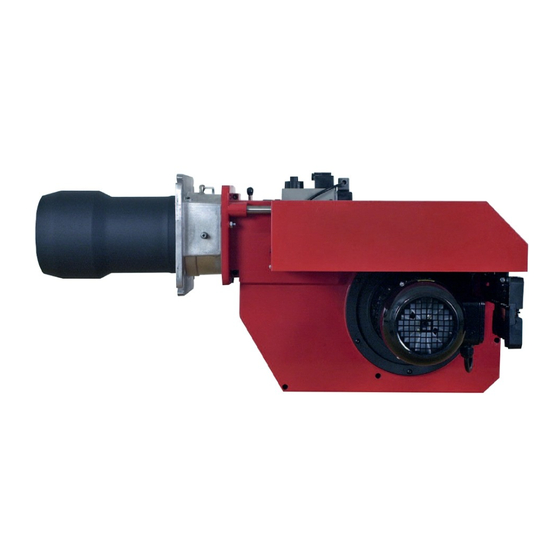
Page 10: Description Bg 550-2
2.6 Description BG 550-2 Components Flame cone Motor Indicating lamp Stage I Connection flange Connection gas fittings Switch 0-l Guide bar Ignition transformer Time meter, stage 1 Fan wheel Air damper Time meter, stage 2 Fan house Air damper motor... -
Page 11: Description Bg 550 M
Time meter Fan wheel Air damper motor Fan house Air pressure switch Contactor with thermal overload protection Shrouded disc Fuse holder Control box Ignition electrode Change-over switch increase- decrease Gas train Nozzle Change-over switch manually- MultiBloc Ionisation electrode automatically Motor Bentone... -
Page 12: General Instructions
Adjust the burner to appr. 20% excess air in accordance with the table. Check the flue gas temperature. Calculate the efficiency. Check also the actual gas volume on the gas meter so that the correct input is achieved. 172 515 03-2 Bentone... -
Page 13: Installation
(see Basic settings). Note that it is only a basic setting which should be adjusted once the burner has been started. If an electric connection other than the one recommended by Enertech is used, a risk of damage and injury can arise. 172 515 03-2 Bentone... -
Page 14: Handling And Lifting Instruction
4.6 Handling and lifting instruction 4.6.1 BG 550, BG 650 The lifting aid used here, is available as spare part. 172 515 34 Bentone... -
Page 15: Mounting On The Boiler
Once the gas flange is fitted to the boiler, it is easy to lift the burner body up onto the guides. Assemble the burner in reverse order to its disassembly. Check the gas tightness. Service position 172 515 30 2018-01-15 Bentone... -
Page 16: Inspection Of Gas Nozzle Before Commissioning
Re-assemble the burner in reverse order to that described above. When re- assembling, make sure that the O-ring located between the gas nozzle and the gas flange is in the correct position when the nozzle is re-fitted. Service position 172 515 31 2018-01-15 Bentone... -
Page 17: Leakage Control
The gas valve is energized and opens and flame is established. At the end of the safety time (2-3 sec.) the gas control locks out. The solenoid valve and the motor will be ”dead”. Remove the link from the gas pressure switch after the test is finished. Bentone... -
Page 18: Gas Nozzle
4.10 Gas nozzle Natural gas Propan Biogas (UV detector) Bentone... -
Page 19: Setting Damper Motor 2-Stage
90° to increase airfl ow. • Return the control switch to position I (low load) and check the combustion values. Solenoid valve High load (black) High load (red) Low load (orange) Closed air damper (blue) Release button 172 511 14-2 2021-05-03 Bentone... -
Page 20: Setting The Burner
A left turn opens the brake plate, providing a lower pressure drop and more air to the combustion process. A right turn closes the brake plate, providing a higher pressure drop and less air to the combustion process. 172 515 32 2018-01-15 Bentone... -
Page 21: Setting The Air Pressure Switch
This is to ensure the reliable function of the burner. If breakdowns or interruptions occur, the air pressure switch is probably set to a too narrow position. Fit the protective cover, screw (Y). Bentone... -
Page 22: Setting The Min. Gas Pressure Switch
The tolerance on the scale for the min. gas pressure switch is approx. ±15%. Open the ball valve. Remove the pressure gauge and close the pressure outlet (X). Check the gas tightness. Fit the protective cover, screw (Y). Bentone... -
Page 23: Skeleton Diagrams
Safety valve Valve proving system Air pressure switch Gas burner control Pos. 5b, 7: Components not required according to EN 676. Required over 1200 kW according to EN 676.hhh 172 515 05 2018-01-02 Bentone... -
Page 24: Multiblock Mb-Zrdle 405-420
2. Knob for adjustment of stage 1 Turn to the left = the start gas fl ow is Test nipple, pressure after governor increased. Test nipple for nozzle pressure Filter Fixing fl ange Ball valve 172 515 11 2018-01-03 Bentone... - Page 25 Turn to the right = the outlet pressure is increased Turn to the left = the outlet pressure is reduced Adjustment of start gas flow Adjustment of governor Multi-bloc MB-ZRDLE 405-420 Flow adjustment 172 515 11 2018-01-03 Bentone...
- Page 26 5.5.1 Pressure taps 1,2,3,4,5 1/8 screwed sealing plug 5.5.2 Electrical connection S 20/S 50 172 515 11 2018-01-03 Bentone...
-
Page 27: Recommended Excess Air When Using Default Setting
Lower heat value Hu at normal state 15°C and 1013.25 mbar EN676 Grade of gas kWh/Nm MJ/Nm kcal/Nm Natural gas 34.02 8126 Natural gas 29.25 6986 Propane 24.6 88.00 21019 Butane 32.5 116.09 27728 172 515 26 2018-01-11 Bentone... - Page 28 Temperature of gas at the gas meter [°C] Barometer reading [mbar] Pressure of gas at the gas meter [mbar] Factor calculated for multiplication with flow in Nm /h to arrive at actual flow in Nm Actual flow · 273+T 1013.25 Bentone...
-
Page 29: Calculating The Quantity Of Gas Supplied
= Time for a certain quantity of gas consumed by the burner. M = Quantity of gas consumed. V = Actual gas flow Calculation example: t = 1 min 10 s M = 450 dm (litre) 0.45 m 1000 0.0194 h 3600 0,45 ≈ 23.2 m 0.0194 Bentone... -
Page 30: Service
Check the ionisation electrode (see chapter Gas nozzle). Replace if necessary. Fit the combustion assembly in reverse order. Press the burner together and lock using the nuts (B). Fit the Euro plugs and turn on the main power supply. Check/adjust the combustion. 172 615 16 2018-01-15 Bentone... -
Page 31: Servicing Air Dampers
Re-install the damper motor and mounting plate on the air intake. Ensure that the damper shaft and control arm are connected correctly. Install the intake grille for the air intake. Press the burner together and lock using the nuts (B). Check/adjust the combustion. Bentone... -
Page 32: Replacement Of Damper Motor, Air
Re-install the damper motor and mounting plate on the air intake. turned. This function facilitates an Ensure that the damper shaft and control arm are connected correctly. exchange of damper motor. Connect the damper motor cable. Fit the Euro plugs and turn on the mains power. Check/adjust the combustion. Bentone... -
Page 33: Vibration
Maximum vibration level are 5,0 mm/s. • Check all bolts and nuts for correct torque. • Check fan wheel for damage and contamination. Change when dirty/ unbalanced. • Check motor bearings. If worn change motor/bearings. Use lid screw for sensor mounting Bentone... -
Page 34: Flame Monitoring And Ionisation Current Check
Required current to ensure detection Min. DC 3 µA Possible detection current Max. DC 20 µA Operational indicator lamp flashes green <5 µA DC Operational indicator lamp shines green >5 µA DC 6.5.1 Flame monitoring ionisation 172 615 02-2 Bentone... - Page 35 Max. current for flame detection Max. DC 5.5 µA Required current to ensure detection Min. DC 40 µA Possible detection current Max. DC 60 µA Operational indicator lamp flashes green <45 µA DC Operational indicator lamp shines green >45 µA DC Bentone...
-
Page 36: Handing Over Of The Installation
• Is the circulation pump in operation? • Is there a supply of fresh air to the installation? • If integral components are of a different make from what is stated in this manual, see the enclosed loose-leaf. 172 615 04 Bentone... -
Page 37: Electric Equipment
Signals must be in different harnesses for safety reasons. Safety system as door switches, water level, pressure, temperature and other safety limiters must be installed in safety loop according to process. 172 615 39 2018-02-23 Bentone... -
Page 38: Wiring Diagram Lme
9.2 Wiring diagram LME Bentone... -
Page 39: Function Lme
Postignition time 2.5 s Safety lockout time < 3 s Reset time after lockout < 1 s Reaction time on fl ame failure < 1 s Min. ionisation current at fl ame 5 µA Max. ionisation current 20 µA Bentone... -
Page 40: Control Program At Faults; Fault Mode Indicator Lme
(waiting period ≥ 10 s) 9.4.1.2 Limiting of starting repetitions LME 11... has a function with start repetition if the flame is not created at start or disappears during operation.. LME 11... allows max. three repetitions during continuous starting cycle. Bentone... - Page 41 3 s. To go back to the normal position, press and hold the reset button longer than 3 s. If the gas burner control is in the alarm position, it is reset by pressing the reset button 0.5...3 s. Bentone...
-
Page 42: Troubleshooting
Burner control faulty Replace Air pressure gauge incorrectly set or faulty Check the settings and reset, or replace No acknowledgement signal due to incorrect adjustment or Check the settings and realign. misalignment of the control motor cams. 172 615 06 2018-01-10 Bentone... - Page 43 Poor draught conditions. Check the chimney. Flue gas temperature too high. Boiler overloaded Decrease the gas volume, sweep the chimney if necessary. content too low. Choke the air supply. Check the boiler for any leakages. Choke the draught if too high. Bentone...
- Page 44 Flame at incorrect angle due to combustion head out of position. Check the combustion head and readjust. Condensation build up in boiler and chimney: Flue gas temperature too low or gas volume too low. Raise the flue gas temperature by increasing gas volume Insulate the chimney. Bentone...
-
Page 45: General Instructions For Gasburners
11. General instructions for gasburners 11.4.1 Installation Follow standards and instructions applicable to the Check that the burner is adapted to the gas quality in installation of gas burners. question. Ensure that the electric installation is made in accordance Check that the input pressure of the gas is correct. with existing regulations. - Page 46 Service- and inspection card Installation Boiler Name: Type: Efficiency kW: Address: Burner Type: Efficiency kW: Installed by: Date: Date gas/h Governor Fluegas Ionisation Pressure Efficiency temp current Fire Chimney room Measu- rement Before After °C µ A mbar mbar Small Flame Large Flame...
- Page 48 Enertech AB. P.O Box 309, SE-341 26 Ljungby. www.bentone.com...
Need help?
Do you have a question about the BG 550-2 and is the answer not in the manual?
Questions and answers