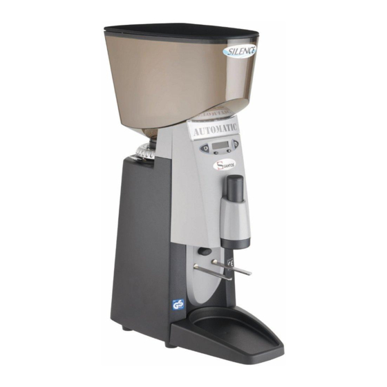

Related Manuals for Santos Silence


Summary of Contents for Santos Silence
- Page 2 Step 1: Has the overload button under the grinder base tripped out? The overload button should be pressed to ensure it is set. Section 1 depress overloAd Button Step 2: If grinder has overloaded then most likely a blockage has occurred. Proceed straight to discharge chute.
- Page 3 Step 1: To access discharge chute, remove front cover by removing Section 2 screws from the inside. 2 screws to remove Step 2: Unclip ribbon cable from screen. lift cABle clip Step 3: Unbolt chute from grinder. 2 Bolts to remove...
- Page 4 Step 4: The chute must be removed and checked for blockage. Section 2 Clean if necessary. ensure throAt is cleAr lift out chute Step 5: Care should be taken for correct orientation of static strip as shown. correct orientAtion 1. tABs to fAce down 2.
- Page 5 Step 1: To remove main upper Burr assembly: Depress the locking tab and unscrew hub. Section 3 unscrew huB hold down AgAinst spring Step 2: Remove lower burr by removing 3 screws from burr. Motor will turn if not held locked with a second locking screwdriver fitted into discharge hole.
- Page 6 Step 4: To Replace upper burr from hub unscrew 3 retaining screws. Section 3 Brush screw heAd Before removing Step 5: Ensure base of hub is squeaky clean. Failure to clean will cause burr to not seat and in turn not grind even. Buff with wire Brush Step 6: Always check the locking tab and spring are free and clean of ground coffee.
- Page 7 Step 7: Screw Hub back into position until Burrs meet. If not at position “0” then remove Section 3 4 screws and set plate to “0”. This plate should be at position “0” when burrs touch. plAte retAiner scews position ‘0’ Step 8: Depress lock tab to release and roughly adjust grind by opening up to position “18”.
- Page 8 Step 1: Remove 2 retaining screws and lift out front panel. Section 4 2 retAining screws Step 2: Remove 3 retaining screws to lift out panel. Unclip ribbon cable by pressing back the clip. Tip: On reassembly ensure 2 long screws are at the top and short screw in bottom centre retAining screws lift cABle clip...
- Page 9 Step 1: Remove old boot by pulling rubber including steel pin located inside, either by hand or pliers. Section 5 Boot & pin AssemBly Step 2: Fit short end of steel pin into replacement boot. replAcement Boot short end fits into Boot Step 3: Ensure rubber boot tabs are correctly tucked away.
Need help?
Do you have a question about the Silence and is the answer not in the manual?
Questions and answers