Table of Contents
Advertisement
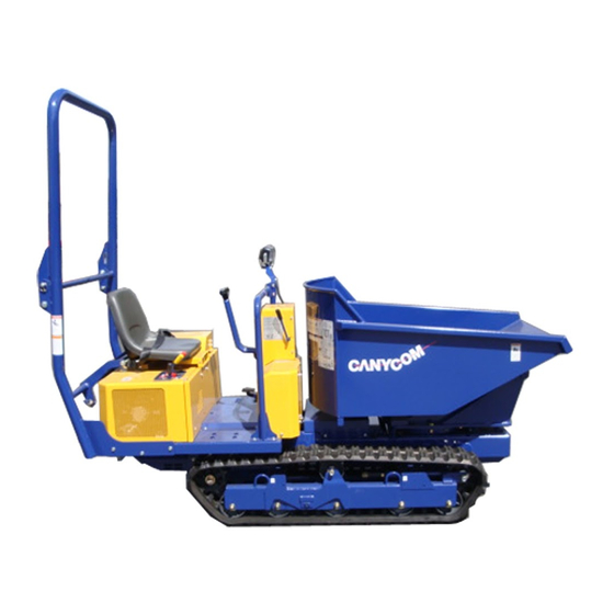
Off-road Rubber Track Dumper
S100
OPERATOR'S MANUAL
Read this manual completely before operating or maintain-
ing this machine. Failure to follow safety precautions could
result in serious injury or death. Keep this manual for
future reference for you and for all those who operate and
maintain this machine.
Feb. 2004,
CHIKUSUI CANYCOM, INC.
90-1 Fukumasu, Yoshiimachi,
Ukihagun, Fukuoka, Japan 839-1396
Tel.(0943)75-2195 Fax.(0943)75-4396
3677 5101 001
Advertisement
Table of Contents

Subscribe to Our Youtube Channel
Summary of Contents for CanyCom S100
- Page 1 Keep this manual for future reference for you and for all those who operate and maintain this machine. Feb. 2004, 3677 5101 001 CHIKUSUI CANYCOM, INC. 90-1 Fukumasu, Yoshiimachi, Ukihagun, Fukuoka, Japan 839-1396 Tel.(0943)75-2195 Fax.(0943)75-4396...
- Page 2 Warning Words Used in This Manual To indicate the level of danger (or the degree of the failure), the following four signal words are used to identify the safety messages in this manual. Their meanings are as follows. Signal word Meaning Indicates an imminently hazardous situation which, if not avoided by following these instructions and precautions, will result in death or serious injury.
- Page 3 Notice to Owner Be sure that everyone who uses this machine, including those who rent or lease this machine, receives a copy of the Operator's Manual and understands the importance of reading and following the information in this manual.
-
Page 4: Table Of Contents
Contents Introduction 1.1 Purpose of This Manual ............1 1.2 Structure of This Manual ............1 1.3 Warning Labels Attached to This Machine ........ 2 Warranty and After-sales Service Rules for Safe Operation and Maintenance Component Names and Functions Product Specifications 5.1 Specifications of This Product .......... - Page 5 6.3 Method of Operating ..............21 6.4 Stopping .................. 23 6.5 Operating Dump ..............25 Maintenance 7.1 Periodic Inspection Table ............28 7.2 Fuel, Lubricant, and Coolant Chart .......... 32 7.3 Replacement Parts Chart ............33 7.4 Adding Oil ................34 ................
- Page 6 ................ 46 7.8.6 Track Tension ............... 47 7.8.7 Steering Lever 7.9 Electrical System ..............49 ................... 49 7.9.1 Fuses 7.10 Maintenance After Use ............50 Storage (Long-term Storage) 8.1 Machine ................... 51 ................. 51 8.1.1 Crawler ................... 51 8.1.2 Clutch 8.2 Battery ..................
-
Page 7: Introduction
Introduction Introduction 1.1 Purpose of This Manual The purpose of this manual is to provide detailed information needed for the safe and effective use of this machine to those who operate or maintain the machine. 1.2 Structure of This Manual This manual contains the following chapters. -
Page 8: Warning Labels Attached To This Machine
Introduction 1.3 Warning Labels Attached to This Machine Replace these labels immediately if they have been removed, fallen off, or have become illegible. Use the part numbers on the label to order replacement labels from dealer. One-way dump 3677M0104010 - 2 -... - Page 9 Introduction Swivel dump 3677M0103050 - 3 -...
-
Page 10: Warranty And After-Sales Service
Warranty and After-sales Service 2. Warranty and After-sales Service Warranty Chikusui Canycom, Inc. provides a warranty to you through their local dealers. Consult your local dealer regarding the details of warranty. After-sales Service Please contact your Canycom distributor from whom you purchased your machine or our Service Center regarding service orders or any questions or problems that may arise when using the Off-road Rubber Track Dumper. -
Page 11: Rules For Safe Operation And Maintenance
Rules for Safe Operation and Maintenance 3. Rules for Safe Operation and Maintenance This chapter describes general safety precautions that must be followed during operation and maintenance. Be sure that all users and maintenance personnel are familiar with these rules and that they follow them. - Page 12 Rules for Safe Operation and Maintenance Do Not Drive Recklessly Do not operate this machine when under the influence of alcohol or when fatigued. No one under age 18 should operate this machine. 3-005 Do Not Start, Accelerate, Turn, or Brake Quickly Maintain Safe Speed When driving the machine, always drive at a safe speed suitable for the load in the dump body and the...
- Page 13 Rules for Safe Operation and Maintenance Work with an Observer in Dangerous Situations When operating the machine where there is poor vis- ibility, rugged terrain, hills, or limited maneuvering room, use an observer to help direct the machine 's movement. The observer should be able to see the machine and its immediate surroundings, and should use pre-arranged signals to direct the driver's actions.
- Page 14 Rules for Safe Operation and Maintenance Precautions When Carrying a Load Never Overload Do not load the machine in excess of the working capacity of 1000kg. 3-011 Load Vehicle Properly Load cargo on the load deck so it is evenly distributed and strap the cargo to the load deck to avoid cargo weight imbalance and shifting.
- Page 15 Rules for Safe Operation and Maintenance Safely Leaving the Machine Unattended Whenever you park the machine, be sure to turn the parking brake switch to the [P] position to apply the park- ing brake, and stop the engine. Remove the key when- ever you leave the machine unattended.
-
Page 16: Component Names And Functions
Component Names and Functions 4. Component Names and Functions Locations One-way dump Swivel dump 3667M-0400-020E - 10 -... - Page 17 Component Names and Functions Component Names and Functions This displays the condition of the battery charge. 1 Charge lamp When the ignition switch is turned to the [I] position, it lights up, and if the condition is normal, it will go out after the engine starts. This lights up when the engine cooling water temperature rises 2 Cooling water tempera- abnormally (overheats).
-
Page 18: Product Specifications
Product Specifications 5. Product Specifications 5.1 Specifications of This Product Read and understand the specifications of this machine to use maintain the machine properly. S100 Machine model, type One-way dump Swivel ump Weight Maximum payload capacity kN(kg) 9.8 (1000) Overall lenght... -
Page 19: Details Of Tool Bag
Product Specifications S100 Machine model, type One-way dump Swivel dump Battery type 75D23R Battery capacity V/AH 12 / 52 Working lamp [V/W] [12 / 18.4] Travel speed km/h 0.0 ~ 5.4 Minimum turning radius 1.55 Gradeability 25 (unloaded) HST fluid capacity... -
Page 20: Operation
Operation 6. Operation • Before reading this section, be sure to read Section 3 "Rules for Safe Operation and Maintenance" (see pages 5 to 9). • When operating the machine, always follow the instructions in this section. Do not operate the machine unless you are familiar with the operation of all controls and safety devices. -
Page 21: Cheking Engine Oil Level And Adding Oil
Operation 6.1.2 Checking Engine Oil Level and Adding Oil If the oil filler cap is opened during operation or immediately after stopping the engine, hot engine oil may spurt out and cause burns since the parts inside the engine cover are heated. Always wait for the engine oil to cool down before open- ing the cap (about 10 minutes after stopping the engine). -
Page 22: Method Of Starting
Operation 1. Open the engine cover, and fix it firmly with the Reservoir tank stay-bar. 2. Check the level of the engine cooling water in the reservoir tank. It should be between the [FULL] and [LOW] lines. If the level is low, add water. Cooling water amount: 1.8 liters Reservoir tank capacity: 0.7 liters Mixing of antifreeze (See page 37) -
Page 23: Normal Starting
Operation 4. Check that the dump lever is in the [NEUTRAL] position, and lock it with the lock plate. 6.2.2 Normal Starting 1. Push the clutch lever to the [ (ON)] position. Clutch lever 2. Depress the parking brake pedal. Parking brake pedal W h e n t h e s t e e r i n g l e v e r i s i n t h e "NEUTRAL"... - Page 24 Operation 3. Push the throttle lever to the [ (HIGH SPEED)] posi- tion. 4. Turn the key in the ignition switch to the [ (PREHEAT)] position and perform the warming-up operation. PREHEAT • Preheat engine for about 10 seconds when starting in normal temperature and for about 20 to 30 seconds when starting in cold weather (ambient tem- perature below -5°C).
- Page 25 Operation Never turn the ignition switch to the [ START ] position when the engine is running. This will damage the starting motor or cause failure of the engine. 6. Check that the warning lamps (oil lamp, cooling water temperature lamp and charge lamp) are off. Warning lamps If the conditions these warning lamps monitor are normal, lamps will go out when the engine starts.
-
Page 26: Starting In Winter Or In Cold Areas
Operation 6.2.3 Starting in Winter or in Cold Areas If the engine is hard to start in winter or in cold areas (at an atmospheric temperature of 0°C or below), start the engine following the procedure below. The load on the battery will be reduced. -
Page 27: Method Of Operating
Operation 6.3 Method of Operating • Do not allow anyone to come near the machine. • The front lower and rear areas of the machine are dead zones. Before operating the machine, remove all obstacles and personnel from these areas. •... - Page 28 Operation When Traveling Forward • Push both steering levers gradually to the front to move the machine slowly forward. The machine Steering lever travel speed can be adjusted by moving the steering levers. When Traveling in Reverse • Push both steering levers gradually to the rear to Reverse move the machine slowly in reverse.
-
Page 29: Stopping
Operation Sudden Turn • To suddenly turn left, push the left steering lever to the rear and the right steering lever to the front. • To suddenly turn right, push the right steering lever to Steering lever the rear and the left steering lever to the front. Sudden Sudden turning... - Page 30 Operation 3. Push the throttle lever to the [ (LOW SPEED)] to lower the speed of the engine. 4. With the parking brake pedal depressed, pull out the Parking brake pedal Parking brake lock lever parking brake lock lever to lock the brake. 5.
-
Page 31: Operating Dump
Operation 6.5 Operating Dump Load deck support bar • Falling load deck can cause injur y or death. • Always fix load deck support bar before doing any work under the load deck. • Do not raise or lower load deck or dump load when anybody is st anding near load deck. - Page 32 Operation 3. Move the dump lever slowly to the (RAISE)] position. 4. When the dump body is raised to the upper limit, a"hiss" sound is heard. Quickly return the dump lever to the [ (HOLD)] position. Lowering the load deck suddenly with a load can damage the machine chassis. Always lower the load deck slowly to prevent damage to the machine chassis.
- Page 33 Operation Swivel Dump When turning the load deck body counter-clockwise 1. Unlock the lock plate. 2. Tilt the turn lever in the direction of forward [ (counter-clockwise turn)]. Maximum angle of rotation: 90 ° 3. When the load deck body is turn to the maximum angle of rotation, a "hiss"...
-
Page 34: Maintenance
Some inspection and maintenance procedures in the table below require tech- nical knowledge or specific tools and measuring instruments. If you have difficulty performing these procedures, or do not have the correct tools or instruments, contact your dealer or a Canycom service center. Inspection interval... - Page 35 If you hear valve noise or Please contact your Engine mally, or if the exhaust condition at the engine is not running ○ Canycom distributor compres- for inspection. idle or at high RPM is abnormal, smoothly, check valve sion check the engine compression.
- Page 36 • Use Ammeter to check for any Must work properly. Please contact your ○ Charging abnormality in function. Canycom distributor system for inspection. • Check that electrolyte level is Must be within specified ○ ○ Inspection / adding: See page: 39 within specified range.
- Page 37 Maintenance Inspection interval Item Content of inspection Remarks • Check the pipe joint and hose joint There must be no oil ○ ○ ○ parts and seal parts for oil leakage. leakage. • Operate the hydraulic pump, and Abnormal vibration and check the pump for abnormal vibra- noise and abnormal ○...
-
Page 38: Fuel, Lubricant, And Coolant Chart
Maintenance Inspection interval Item Content of inspection Remarks • Check for cracks, deformities, or No cracks, noticeable ○ ○ ○ Machine corrosion. deformities, or corrosion. frame and • Check for missing or loose bolts There must be no loose or ○... -
Page 39: Replacement Parts Chart
Battery 3673 0655 000 Replace if defective. * Special replacement parts ► Please contact your Canycom distributor ( or our Service Center). Rubber parts such as hydraulic hoses will deteriorate even when not used. Replace them every 2 years, or whenever damaged. -
Page 40: Adding Oil
Maintenance Adding Oil ● Insufficient or improper lubrication reduces performance and may cause the machine to break down, shortening the life of the machine. Always keep machine filled with the right amount of designated good quality oil. ● Always check remove and add oils on a horizontal surface after stopping the engine. -
Page 41: Transmission Fluid
Maintenance 7.4.2 Transmission Fluid Inspection / Adding Safety cover 1. Remove the safety cover. 2. Remove the fluid level port bolt, and check that the fluid level is at the fluid level port. 3. Visually check the transmission fluid level and the condition of dirt in the fluid. -
Page 42: Hst Fluid (Hydraulic Fluid)
Maintenance 7.4.4 HST Fluid (Hydraulic Fluid) • Low fluid levels may decrease hydraulic performance, periodically check the fluid level and add fluid if the level is low. • The HST fluid is also used as the hydraulic fluid. Add the fluid to the hydraulic tank. Inspection / Adding Fluid 1. -
Page 43: Lubricating
Maintenance 7.5 Lubricating Proper lubrication will prevent seizures and rust, and ensure smooth oper- ation. Lubricate every 6 mouths. Lubricate the illustrated points. One-way dump Lubrication Lubrication area Type of lubrication points Parking brake pedal link section Clutch lever pivot Hydraulic cylinder pivot •... -
Page 44: Adding Water
Maintenance 7.6 Adding Water 7.6.1 Engine Cooling Water • Wait for engine to cool after operation (about 10 minutes) before opening radia- tor cap. Opening cap too soon may release boiling water and cause burns. • Take extreme care not to approach it to a fire because anti-freezing solution is inflammable. -
Page 45: Battery Electrolyte
Maintenance Replacement 1. Prepare a suitable container to catch drained cooling water. 2. Remove the drain bolt located at the bottom of the radiator. Drain bolt 3. Drain cooling water and clean the inside of the radi- ator. Reference: When the radiator cap is removed, cooling water can be drained more easily. - Page 46 Maintenance Charging ● Always remove the battery from the machine before charging it. Failure to do this will cause damage to electrical components and to the wiring. ● When connecting cables to the battery, use the correct (+) and (-) terminals. Reversing connections will blow the fuse and prevent charging.
-
Page 47: Cleaning And Replacement
Maintenance 7.7 Cleaning and Replacement 7.7.1 Air Cleaner Element ● Dirty air cleaner element will reduce engine performance and life. Clean every 100 hours of operation. ● Handle the air cleaner element taking care not to break or deform it. Cleaning Air cleaner 1. -
Page 48: Engine Oil Filter
Maintenance 7.7.2 Engine Oil Filter Cartridge 1. Prepare a suitable container to catch the drained oil. Oil filter 2. Drain the engine oil. (See page 34) 3. Open the engine cover, and lock it with the stay- bar. (See page 15) 4. -
Page 49: Suction Filter And Line Filter
Maintenance 7.7.3 Suction Filter and Line Filter Inside of a tank Replace suction filter and line filter element whenever changing hydraulic oil. Replacement 1. Remove the suction filter (use a filter wrench to Suction filter remove the line filter). 3677M-0707-060 Avoid contact with high temperature oil to avoid burns. -
Page 50: Adjustments
Maintenance 7.8 Adjustments 7.8.1 Bleeding Air from Fuel System To avoid engine starting malfunction, bleed air from fuel system after fuel filter or fuel pipe replacements, or after any operation when fuel tank was completely emp- tied. 1. Fill the fuel tank with fuel. 2. -
Page 51: V-Belt For Traveling
After loosening the lock nut, and adjust the spring hook inner dimension to 114 to 118 mm by turning the turnbuckle. 114~118mm Replacement Contact your Canycom distributor. 7.8.4 hydraulic pressure V-belt Inspection Adjustment nut 1. Open the engine cover, and lock it with the stay-bar. -
Page 52: Fan Belt Tension
Maintenance 7.8.5 Fun Belt Tension Fan belt If the tension of the cooling fun belt is small, the belt is slipped and not only the cooling capacity of the engine is lowered but also the service life of it is shortened. -
Page 53: Steering Lever
Maintenance 7.8.6. Steering Lever The steering lever is properly adjusted when the machine is properly shipped from the factory, so normally there is no need to adjust it. If the steering lever and links have been replaced, the steer- Cover ing lever must be adjusted. - Page 54 Maintenance If Right Crawler Moves Right Left 1. Loosen two lock nuts (A). Steering lever (Right) Steering lever (Left) 2. Rotate rod (B) slowly until crawler does not move. • If the crawler moves forward, adjust the rod so the distance (L) between two link balls (C) becomes shorter.
-
Page 55: Electrical System
Maintenance 7.9 Electrical System 7.9.1 Fuses Inspection Fuses in the wiring circuits will prevent damage to electrical systems. Check fuses whenever electrical problems occur. Open the battery box cover, and check that no Slow blow fuse fuse is blown. Slow Blow Fuse •... -
Page 56: Maintenance After Use
Use warm or hot water to melt the frozen parts or wait for the ice to melt. Be careful when moving the machine. If the machine is moved by force, Canycom does not take responsibility for damage or failure. - 50 -... -
Page 57: Storage (Long-Term Storage)
Storage (Long-term Storage) 8. Storage (Long-term Storage) When storing for a long time, it is necessary to take suitable action to prepare for the next time that the machine is used. When preparing for long-term storage, carry out "Maintenance after use"... -
Page 58: Battery
Storage (Long-term Storage) 8.2 Battery When disconnecting the cables from the battery, disconnect the (-) terminal first, and the (+) terminal last; when connecting the cables, connect the (+) terminal first, and the (-) terminal last. 1. Remove the battery from the machine. 2. -
Page 59: Replacing Engine Oil
Storage (Long-term Storage) 8.3.2 Changing Engine Oil Drain the engine oil, then fill with fresh engine oil. (See page 32) Oil drain plug 3677M-0704-030 8.3.3 Fuel Cock Turn the fuel cock to the [OFF] position to cut off the fuel supply. -
Page 60: Troubleshooting
→ Replace ・ Defective contact or → Repair disconnection in electric (Please contact your wiring Canycom distributor) ・ No fuel → Add fuel (See page 14) Engine dose not start or ・ Air leak in fuel system is difficult to start →... - Page 61 Excessive consumption ・ Wear of cylinder, piston ring → Check and repair (Please of engine oil contact your Canycom distributor) ・ Lack of engine oil → Add oil (See page 34) ・ Lack of engine cooling water → Add water (See page 38) ・...
- Page 62 ・ Parking brake is applied → Release parking brake ・ Problem in hydraulic system → See Hydraulic related (See page 56) ・ Failure inside HST → Please contact your Canycom distributor Machine does not move ・ Overloaded → Reduce load even when steering ・...
- Page 63 Troubleshooting Location Problem Main causes Remedy ・ Oil leakage from hydraulic → Inspect and repair → Inspect and repair Dump Dump device does not system ・ Foreign matter clogged in device operate control valve ・ Oil leakage from hydraulic → Inspect and repair →...
-
Page 64: Transporting Machine
Transporting Machine 10. Transporting Machine When loading and unloading this machine onto a truck for transportation, follow these safety precautions. 10.1 Truck Loading and Unloading 1. Use ramps that have ample strength (that can hold the total weight of the machine and operator), width (at least 1.2 times the width of the crawler), and length (at least 3 times the height of the bed of the truck), and are fitted with no-slip pads. -
Page 65: Lifting By Crane
Transporting Machine 10.2 Lifting by Crane Always unload machine before lifting. 1. Hitch the wire rope to the lifting hooks (4 places) attached to the frame at right and left side front and rear positions, and lift the machine from the lateral center of the machine. - Page 66 CHIKUSUI CANYCOM, INC. ■ Sales Headquaters TEL 0943(75)2195 FAX ■ Osaka Center TEL 0790(42)6031 FAX (75)4396 (42)6035 ■ Foreign Trade Center TEL 03(3552)6277 FAX (3552)6288 ■ Hiroshima Center TEL 0824(34)5996 FAX (34)5997 ■ To k y o C e n t e r TEL 03(3552)6255 FAX (3552)6288 ■...
Need help?
Do you have a question about the S100 and is the answer not in the manual?
Questions and answers