Sign In
Upload
Manuals
Brands
Phoenix Contact Manuals
Control Unit
Axioline F AXL F SSDO8/3 1F
Phoenix Contact Axioline F AXL F SSDO8/3 1F Manuals
Manuals and User Guides for Phoenix Contact Axioline F AXL F SSDO8/3 1F. We have
1
Phoenix Contact Axioline F AXL F SSDO8/3 1F manual available for free PDF download: User Manual
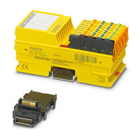
Phoenix Contact Axioline F AXL F SSDO8/3 1F User Manual (110 pages)
module with integrated safety logic and safe digital outputs
Brand:
Phoenix Contact
| Category:
Control Unit
| Size: 2 MB
Table of Contents
Table of Contents
5
1 For Your Safety
9
General Safety Notes
9
Electrical Safety
10
Safety of the Machine or System
11
Directives and Standards
11
Intended Use
11
Documentation
12
Abbreviations Used
12
Safety Hotline
12
2 Product Description
13
Note about the System Description
13
Short Description of the Module
13
Structure of the Module
14
Housing Dimensions
14
Safe Digital Outputs
15
Connection Options for Actuators Depending on the Parameterization
16
Local Diagnostics and Status Indicators
17
Safe State
19
Operating State
19
Error Detection in I/O Devices
19
Device Errors
20
Parameterization Errors
20
Process Data Words
21
Programming Data/Configuration Data
21
3 Integration of the Axioline F Local Bus
23
Supply Voltage of the Module Logic
23
Supply Voltage U
24
DC Distribution Network According to IEC 61326-3-1
25
Terminal Point Assignment
25
4 Assembly, Removal, and Electrical Installation
27
Assembly and Removal
27
Unpacking the Module
27
Preparation and Assembly
27
Setting the DIP Switch
28
Mounting and Removing the Module
29
Electrical Installation
31
Electrical Installation of the Axioline F Station
31
Electrical Installation of the Module
31
5 Parameterization of the Module
33
Parameterization in a Safetybridge System
33
Parameterization of the Safe Outputs
34
Behavior of the Outputs in the Event of Enabled Switch-Off Delay for Stop Category 1
35
6 Connection Examples for Safe Outputs
37
Explanation of the Examples
37
Notes on the Protective Circuit of External Relays/Contactors (Freewheeling Circuit)
39
Measures to Achieve a Specific Safety Integrity
39
Single-Channel Assignment of Safe Outputs
41
Two-Channel Assignment of Safe Outputs
43
7 Startup and Validation
47
Initial Startup
47
Startup Mode
48
Restart after Replacing a Module
49
Replacing a Module
49
Restart
49
Validation
49
8 Errors: Messages and Removal
51
Displaying and Reading Errors
51
Acknowledging an Error
51
Module Replacement Following an Error
51
Note about the Error Codes
52
Error Codes
53
9 Maintenance, Repair, Decommissioning, and Disposal
59
Maintenance
59
Repair
59
Decommissioning and Disposal
59
10 Technical Data and Ordering Data
61
Safetybridge System Data
61
AXL F LPSDO8/3 1F Module Data
61
Conformance with EMC Directive
65
Ordering Data: Module
66
Download Data: Software
66
Download Data: Documentation
66
A Appendix: Safetybridge System
67
A 1 Features and Basic Specifications of the System
67
A 2 System Topology
69
A 2.1 General Topology
69
A 2.2 Network and Controller Requirements
70
A 2.3 Safe Input and Output Devices
70
A 2.4 Cross Communication
71
A 3 Safetybridge Address Assignment
76
A 4 Safetybridge V3 System Handling in Various Control Systems
80
A 5 Feedback Data
80
A 6 Enable Principle
80
A 7 Diagnostics
83
Error Detection in I/O Devices
83
A 7.2 Detection of Device Errors
84
A 7.3 Acknowledgment of Error Messages for Satellites
84
A 8 Configuration, Parameterization, and Download
85
A 8.1 Configuration and Parameterization Using the SAFECONF Configuration Software
85
A 8.2 Downloading the Configuration and Parameter Data Record
86
A 9 Safe State
86
A 10 Time Response in the Safetybridge System
87
A 10.1 Typical Response Time
87
A 10.2 Shutdown Times
88
A 11 Achievable Safety Depending on the Modules Used
90
A 12 Behavior in the Event of an Error
90
A 12.1 Critical System or Device Errors
91
A 12.2 Parameterization or Configuration Errors
91
A 12.3 Communication Errors
92
A 12.4 I/O Errors
92
A 12.5 Application Errors
92
A 13 Startup and Restart
93
A 13.1 Startup/Restart Following Power up
93
A 13.2 Restart after Triggering a Safety Function
93
A 14 Memory Sizes for the Safety Logic
94
B Appendix: Checklists
95
B 1 Checklists for the Safetybridge System
96
Planning
96
B 1.2 Configuration and Parameterization
98
B 1.3 Startup
99
Safety Functions
100
B 1.5 Validation
101
Checklists for the AXL F LPSDO8/3 1F Module
102
Planning
102
B 2.2 Assembly and Electrical Installation
103
B 2.3 Startup and Parameterization
104
B 2.4 Validation
105
C Appendix: Index
107
D Appendix: Revision History
109
Advertisement
Advertisement
Related Products
Phoenix Contact Axioline F AXL F BK Series
Phoenix Contact Axioline AXL F SSDI8/4 1F
Phoenix Contact FL SWITCH SMN 8TX-PN
Phoenix Contact SCK-C-MODBUS
Phoenix Contact SCK-M-I-4S-20A
Phoenix Contact AXL E S3 DI8 DO8 M12 6P
Phoenix Contact AXL E S3 IOL8 DI4 M12 6P
Phoenix Contact SCX 4POE 2LX
Phoenix Contact SHDSL Series
Phoenix Contact FL MGUARD SMART2
Phoenix Contact Categories
Controller
Switch
Power Supply
Control Unit
Industrial Equipment
More Phoenix Contact Manuals
Login
Sign In
OR
Sign in with Facebook
Sign in with Google
Upload manual
Upload from disk
Upload from URL