Table of Contents
Advertisement
Quick Links
IMPORTANT!
Read all instructions in this manual before operating pump.
As a result of Crane Pumps & Systems, Inc., constant product improvement program,
product changes may occur. As such Crane Pumps & Systems reserves the right to
change product without prior written notifi cation.
A Crane Co. Company
420 Third Street
Piqua, Ohio 45356
Phone: (937) 778-8947
Fax: (937) 773-7157
www.cranepumps.com
BARNES
BARNES
SERVICE MANUAL
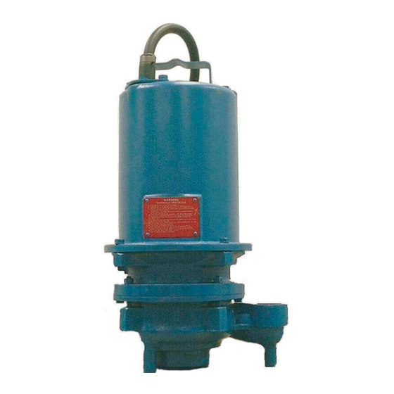
SGV 2 HP Pump
®
83 West Drive, Bramton
Ontario, Canada L6T 2J6
Phone: (905) 457-6223
Fax: (905) 457-2650
Form No. SM108091-Rev. B
Advertisement
Table of Contents

Related Manuals for Crane Barnes SGV 2 HP


Summary of Contents for Crane Barnes SGV 2 HP
- Page 1 Read all instructions in this manual before operating pump. As a result of Crane Pumps & Systems, Inc., constant product improvement program, product changes may occur. As such Crane Pumps & Systems reserves the right to change product without prior written notifi cation.
-
Page 2: Table Of Contents
Parts Kits /Parts List ....................30 Other brand and product names are trademarks or registered trademarks of their respective holders. ® Barnes is a registered trademark of Crane Pumps & Systems, Inc © Crane Pumps & Systems, Inc. 2004, 7/06... -
Page 3: Safety First
If the pump is idle for long periods of time, it is advisable to start IMPORTANT! - Crane Pumps & Systems, Inc. is not the pump occasionally by adding water to the basin. responsible for losses, injury, or death resulting from a... -
Page 4: Tool List
TOOL LIST • Cresent Wrench • Torque Wrench • Hammer • Brass Flat Punch • 3/8” Ratchet • 3/8” Short Extension • 1/2” Wrench Open End • 2 - 3/16” Flat Blade Screwdrivers • 1/4” Nut Driver • 1/8” Allen Wrench •... -
Page 5: Sgv 2Hp Disassembly
SGV 2HP Disassembly Visual Inspection of Pump Quick visual inspections can save time. A visual Examination of the pump for damage to cords, controls, or cutter, and a thorough electrical check should be performed to determine a pumps condition. Cut Cords Check the cord(s) for any cuts or gouges. -
Page 6: Jammed Or Worn Cutter
Readings should be as follows: (1 Phase motor)(Approximate) Red to Black = 7.7 to 8.3 Start & Run Resistance Red to White = 6.3 to 7.2 Start Resistance Black to White = 1.1 to 1.7 Run Resistance (All fi gures are approximate, variances may occur as results of pump motor manufacturer specs, and or, direct burial cable of varying lengths.) The totals of the two low fi... -
Page 7: Cutter Removal
Cutter Removal CAUTION: Sharp edges, use caution when removing cutter. NOTE: Prior to disassembly, mark castings with a permanent marker on all joints to assist in realignment. With the pump lying on its side, remove the cutter retaining screw and washer. The screw has green loctite so apply heat to the screw, wedge a fl... -
Page 8: Volute
Volute Remove the four nuts and lock washers from the volute studs. Remove volute and square ring from pump. To remove or reverse the shredding ring, fi rst remove the three fl at head allen screws. The screws are installed with loctite so apply heat to screws before removing, and lift the throat out of the body. -
Page 9: Seal Chamber
Seal Chamber Place unit on its side with oil fi ll plug downward, remove plug (a 3/8” drive socket extension works well) and drain all oil from seal chamber, checking oil for contamination (milky white oil indicates the presence of water.) Perform Pressure Check NOTE: This test is to be performed with NO oil in the housing. -
Page 10: Impeller
Impeller The impeller can be removed by turning it counterclockwise while holding the motor shaft stationary with a screwdriver. CAUTION: Use Caution to not damage threads on shaft. NOTE: With impeller removed, the seal spring is relaxed and some oil may seep from the seal chamber. Do not store this pump without the impeller in place to hold pressure on the seal spring. -
Page 11: Outer Shaft Seal
Outer Shaft Seal CAUTION: Handle seal parts and shaft with extreme care. Do not scratch or mar lapped or machined surfaces. Remove spring and rotating member from shaft. Examine all seal parts and especially contact faces. Inspect seal for signs of wear, such as uneven wear tracks on stationary members, chips, and scratches on either seal face. -
Page 12: Seal Plate
Seal Plate Remove two bolts and washers from seal plate. Remove seal plate and square ring from intermediate coupling. Remove stationary seal by pressing out with fl at screwdriver. Inspect square-ring for signs of wear and abrasion. Press out stationary seal using care to not damage seal surfaces. -
Page 13: Motor, Bearing, Inner Seal
Motor, Bearing, Inner Seal Set unit on its side and remove plug from motor housing, drain all oil from motor chamber. CAUTION: Oil can be under pressure and hot! NOTE: Perform pressure check on motor housing, reference back to page 10. -
Page 14: Motor Housing
Motor Housing NOTE: Position unit upright, using 4” pvc coupler to avoid resting unit on the lower shaft. Loosen cable clamp bolts and lock washers from motor housing. Remove cord from motor housing by pulling straight up while using a rocking motion. Remove retaining snap ring with a medium fl... - Page 15 Motor Housing (con’t) Remove motor housing bolts and washers and vertically lift motor housing from intermediate coupling. Remove square ring from intermediate coupling. Inspect square ring for signs of wear and abrasion...
-
Page 16: Motor
Motor Remove stator bolts and carefully remove stator housing from rotor. Remove snap ring from intermediate coupling, rotor will pull out of intermediate coupling with bearing and rotating member of inner seal attached. -
Page 17: Bearings
Bearings From rotor shaft remove rotating member and spring. Now bearing can be removed from rotor shaft by removing snap rings from shaft and using a wheel puller or arbor press. Upper rotor bearing may be removed from rotor shaft with a bearing puller. -
Page 18: Inner Seal
Inner Seal From intermediate coupling, press out stationary seal with a fl at screwdriver. -
Page 19: Sgv 2 Hp Assembly
SGV 2 HP Assembly Bearings to Pump Rotor When replacing bearings, be careful not to damage the rotor or shaft threads. Using an arbor press, hold the rotor and press the upper bearing on the rotor shaft, applying force to the inner race of the bearing only. -
Page 20: Inner Seal
Inner Seal CAUTION: Handle seal parts and shaft with extreme care! Do not scratch or mar lapped surfaces. Clean and oil seal cavities in intermediate coupling. Lightly oil (DO NOt grease) outer surface of stationary member. Press stationary member fi rmly into intermediate coupling, using a seal pusher (see parts list - Seal Tool Kit). -
Page 21: Motor
Motor Slide motor rotor, with bearings and inner seal into intermediate coupling. Insert bearing retaining ring into intermediate coupling. Set wave spring on top of upper bearing, hold in place with small amount of grease. Set motor stator over rotor being sure that stator drops fl at against register in coupling. Place end bell on top of motor and insert motor bolts in motor and torque to 17 in/lb. -
Page 22: Motor Housing
Motor Housing Lubricate and set square ring into bore on intermediate coupling. Install ground wire in end bell if removed (Use proper bolt to secure ground lug). Place fi berglass sleeve over motor and ground leads if removed. Pull wires through opening in top of motor housing while lowering motor housing onto intermediate coupling. -
Page 23: Wiring Schematic/Pin Placement
Pin Placement Diagram Figure B B Figure... -
Page 24: Seal Plate
Seal Plate Lubricate and set square ring in bottom groove of seal plate. Guide seal plate over end of rotor shaft, install and tighten two washers and bolts to 6.5 ft/lbs. Be sure square ring is in groove on coupling and not twisted. -
Page 25: Outer Seal
Outer Seal Clean and oil stationary seal cavity in seal plate. Slide seal guide (see parts list - Seal Tool Kit) over motor shaft. Lightly oil (do not grease) outer surface of stationary seal. Press stationary seal fi rmly into seal plate using a seal pusher. -
Page 26: Impeller
Impeller Assemble impeller on motor shaft, with machined step fi tting inside I.D. of seal spring, by turning clockwise while holding shaft stationary with a screwdriver. -
Page 27: Valute, Shredding Ring, & Cutter
Valute, Shredding Ring, & Cutter Next install shredding ring into the volute body with the use of an arbor press. Insert throat into body with three fl at head Allen screws, use green loctite on threads. Lubricate square ring and place on groove in bottom seal plate. Place volute on seal plate being careful not to damage square ring. -
Page 28: Replacing Oil
NOTE: Repeat all electrical checks & pressure tests prior to replacing oil. Replacing Oil Motor housing - Set unit upright and refi ll with (see chart for type and amount) new cooling oil. Fill to 1” above motor as an air space must remain in the top of the motor housing to compensate for oil expansion. -
Page 29: Pump Exploded View
SGV 2HP Exploded View Figure Figure C C... -
Page 30: Parts Kits /Parts List
PARTS KITS Seal Repair Kit ...P/N: 113299 Item #’s 6,7,13,14,15,19,20,21,25,26,27,32,35,47 Overhaul Kit ....P/N: 115946 Item #’s 6,7,13,14,15,19,20,21,23,25,26,27,28,29,32,35,47,55 Cutter Kit - SGVF ..P/N: 113300 Item #’s 5,6,7,9,15,19,23 Cutter Kit - SGVH ..P/N: 113300B Item #’s 5,6,7,9,15,19,23 PARTS LIST ITEM PART NO. DESCRITION ITEM QTY. - Page 31 Notes...
- Page 32 CRANE PUMPS & SYSTEMS, INC. 420 THIRD STREET PIQUA, OHIO 45356 - U.S.A.
Need help?
Do you have a question about the Barnes SGV 2 HP and is the answer not in the manual?
Questions and answers