Table of Contents
Advertisement
Quick Links
CONTENTS
SAFETY CONSIDERATIONS . . . . . . . . . . . . . . . . . 1
INSTALLATION . . . . . . . . . . . . . . . . . . . . . . . . . . . . 1-13
• UNPACK UNIT
• INSPECT SHIPMENT
• BEFORE INSTALLATION
Step 2 − Select Location . . . . . . . . . . . . . . . . . . . . 4
Step 3 − Mount Unit . . . . . . . . . . . . . . . . . . . . . . . . 6
Step 4 − Connect Refrigerant Piping . . . . . . . . 7
Step 6 − Make Electrical Connections . . . . . . 11
Step 7 − Install Remote Thermostat . . . . . . . . 12
Indoor and Outdoor Units . . . . . . . . . . . . . . . . 12
• COOLING ONLY SYSTEMS
START-UP . . . . . . . . . . . . . . . . . . . . . . . . . . . . . . . 13-15
After Extended Shutdown . . . . . . . . . . . . . . . . . . 13
Seasonal Changeovers . . . . . . . . . . . . . . . . . . . . . 13
Operating Mode Memory . . . . . . . . . . . . . . . . . . . 14
Automatic Operation (Auto.) Mode . . . . . . . . . . 14
Operating Sequence . . . . . . . . . . . . . . . . . . . . . . . 14
• DEFROST (40QAE ONLY)
CLEANING AND MAINTENANCE . . . . . . . . . . . 15,16
Lubrication . . . . . . . . . . . . . . . . . . . . . . . . . . . . . . . . 15
Air Filters . . . . . . . . . . . . . . . . . . . . . . . . . . . . . . . 15
To Clean Indoor Unit Bottom Panel . . . . . . . . . 16
To Clean Indoor Coil . . . . . . . . . . . . . . . . . . . . . . . 16
To Clean Outdoor Coil (Outdoor Unit) . . . . . . . 16
To Clean Condensate Drains . . . . . . . . . . . . . . . . 16
SERVICE . . . . . . . . . . . . . . . . . . . . . . . . . . . . . . . . . . 16
Before Calling for Service . . . . . . . . . . . . . . . . . . 16
FRESH AIR INSTALLATION OPTIONS . . . . . . . 16
Ventilation-Air Accessory . . . . . . . . . . . . . . . . . . . 16
TROUBLESHOOTING . . . . . . . . . . . . . . . . . . . . . 17-20
START-UP CHECKLIST . . . . . . . . . . . . . . CL-1, CL-2
Manufacturer reserves the right to discontinue, or change at any time, specifications or designs without notice and without incurring obligations.
Book 1 4
PC 111
Catalog No. 534-052
Tab
3d 2d
Installation, Start-Up
and Service Instructions
Page
Printed in U.S.A.
Ceiling-Suspended Fan Coil Units
SAFETY CONSIDERATIONS
Installing and servicing air-conditioning equipment can be
hazardous due to system pressure and electrical compo-
nents. Only trained and qualified service personnel should
install or service air-conditioning equipment.
Untrained personnel can perform basic maintenance, such
as cleaning and replacing filters. All other operations should
be performed by trained service personnel. When working
on air-conditioning equipment, observe precautions in lit-
erature and on tags and labels attached to unit.
Follow all safety codes. Wear safety glasses and work gloves.
Use quenching cloth for brazing operations. Have fire ex-
tinguisher available. Read these instructions thoroughly. Con-
sult local building codes and National Electrical Code (NEC)
for special installation requirements.
Before installing or servicing system, always turn off
main power to system. There may be more than one dis-
connect switch. Turn off accessory heater power if ap-
plicable. Electrical shock can cause personal injury.
INSTALLATION
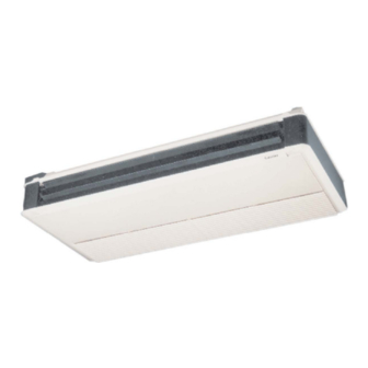
The 40QAB ceiling-suspended fan coil unit (Fig. 1) is typi-
cally installed with the 38HDC or 38HDS outdoor condens-
ing unit, and the 40QAE unit is typically installed with the
38QRC heat pump.
NOTE: The 40QAE unit can also be installed with either the
38HDC or HDS condensing units. Refer to Table 1 to make
sure the correct indoor unit(s) is installed with the correct
outdoor unit.
Installation instructions for 40QA fan coil units are con-
tained in this manual. Refer to this manual for proper in-
stallation of the complete system. Note that the outdoor units
are shipped with installation and service instructions for ba-
sic installation of the outdoor section. Be sure to make the
connections in Cooling-Only Systems and Heat Pump Sys-
tems sections on page 12 of this literature so that the unit
will operate properly with the 40QA mircoprocessor control
system.
Fig. 1 - 40QA Ceiling-Suspended Fan Coil Unit
Form 40QA-3SI
Pg 1
40QA024-060
4-96
Replaces: 40QA-1SI
Advertisement
Table of Contents

Related Manuals for Carrier 40QA


Summary of Contents for Carrier 40QA
-
Page 1: Table Of Contents
• SPECIAL OPERATION, HEATING Installation instructions for 40QA fan coil units are con- CLEANING AND MAINTENANCE ... 15,16 tained in this manual. Refer to this manual for proper in- Lubrication . - Page 2 field-supplied. Be sure you have the required parts before beginning instal- lation. The 40QA unit utilizes a standard 24 v control sys- tem (see Tables 3A and 3B) for ultimate flexibility while de- livering optimal levels of comfort and efficiency. Be sure to follow these instructions carefully to obtain proper function- ing of the unit.
-
Page 3: Step 1 - Complete Pre-Installation Checks
Table 3A — Physical Data, 40QAB Cooling-Only Units UNIT 40QAB 024* NOMINAL CAPACITY (Tons) ⁄ NOMINAL SIZE (Btuh) 18,000 24,000 36,000 36,000 60,000 OPERATING WEIGHT (lb) MOISTURE REMOVAL RATE (Pints/Hr) 13.4 15.1 FINISH GM Motorhome White with Black Trim REFRIGERANT R-22 Control (Cooling) AccuRater Piston in Fan Coil Unit/TXV in Condensing Unit... -
Page 4: Step 2 − Select Location
Table 3B — Physical Data, 40QAE Heat Pump Units UNIT 40QAE 024* NOMINAL CAPACITY (Tons) ⁄ NOMINAL SIZE (Btuh) 18,000 24,000 36,000 48,000 60,000 OPERATING WEIGHT (lb) MOISTURE REMOVAL RATE (Pints/hr) 13.4 15.1 FINISH GM Motorhome White with Black Trim REFRIGERANT R-22 Control (Cooling) - Page 5 5-11 ⁄ 1817 5- 6 ⁄ 1692 5-10 ⁄ 1783 1- 9 ⁄ 555 3- 3 ⁄ 7- 8 2336 7- 3 2211 7- 6 ⁄ 2302 1-11 ⁄ 601 4-11 ⁄ 1512 Fig. 3 — 40QA Base Unit Dimensions...
-
Page 6: Step 3 - Mount Unit
If proper pitch cannot be achieved, install accessory condensate pump at this time. Fig. 5 — 40QA Unit Mounting Methods Step 3 — Mount Unit — Refer to Fig. 4 for clearances (Hardware is Field Supplied) and dimensions. -
Page 7: To Install Remote Thermostat
A pis- ton is shipped in the AccuRater device body (Fig. 13) with the 40QA unit. Use Tables 4-6 to verify that you Fig. 9 — Removing Rear Knockout in Side Panel... - Page 8 HEX-HEAD *Factory supplied. BOLT Fig. 12 — Routing Wires Over Piping Fig. 11 — Hanging 40QA Unit e. On heat pump (38QRC) installations, install factory- IMPORTANT: The factory-supplied piston MUST supplied piston (enclosed in a bag taped inside the out- be installed as shown in Fig.
- Page 9 4. Evacuate piping, if necessary. If either refrigerant piping or the indoor coil is exposed to atmospheric conditions, it must be evacuated to 1000 microns to eliminate con- tamination and moisture in the system. Refer to Carrier’s Standard Service Techniques Manual, Chapter 1, Sec- tions 1-7.
-
Page 10: Step 5 - Connect Condensate Drain Line
4. Attach drain pipe with nylon wire tie passing through hole Step 5 — Connect Condensate Drain Line (Fig. 16). — Observe all local sanitary codes when installing conden- NOTE: Do not fasten nylon wire ties tight enough to de- sate drains. -
Page 11: Step 6 - Make Electrical Connections
Table 7 — Electrical Data Volts MINIMUM MAXIMUM HEATER POWER UNIT WIRE (Single-Ph, OPERATING OPERATING Motor 1 Motor 2 40QA SIZE 60 Hz) VOLTAGE* VOLTAGE* MOCP (AWG) ⁄ − − − − 1.50 1.20 B024†... -
Page 12: Step 7 − Install Remote Thermostat
Step 7 — Install Remote Thermostat — The 40QA complete. unit is equipped with a remote thermostat which operates the system. The thermostat monitors the system operation Wire thermostat to fan coil unit according to Fig. 20 (cooling- and controls the operating mode. -
Page 13: Start-Up
Mode Air Sweep TB — Terminal Block *Heat pump units only. Day/Night Fig. 20 — Cooling Only Systems or Condensing Unit Matched with Heat Pump Fan Coil Unit Thermostat Wiring 2. Make sure that all wiring connections are correct and that they are tight. -
Page 14: Adjusting Airflow
Operating Mode Memory — After the system is turned off or after a power failure, the system remains in the last operating mode selected. When the system is turned back on, or when power is automatically restored, operation con- tinues in the same operating mode as when the system shut down. -
Page 15: System Safeties
B. Condensate float switch (40QA units equipped with ac- ing performance, intermittent system operation, frost cessory condensate pump, cooling cycle only) — If the build-up on the indoor coil, and blown fuses. -
Page 16: To Clean Or Replace Filters
FRESH AIR INSTALLATION OPTION TO CLEAN OR REPLACE DRAIN PAN The 40QA units have an installation option which allows 1. Place a plastic sheet on the floor to catch any water that for field installation of fresh air ventilation. Plan your in- may spill from drain pan. -
Page 17: Troubleshooting
*If fuse blows or circuit breaker trips again after first start attempt, DO †When outdoor temperature is approximately 55 F or below, indoor NOT attempt to start system again. Contact your local Carrier rep- coil frosting may occur when system is operated in cooling or maxi- resentative for assistance. - Page 18 LEGEND AND NOTES (Fig. 25 and 26) LEGEND — Overload — Air Sweep Motor — Printed Circuit Board — Air Sweep Relay — Pump Delay Relay — Air Sweep Switch — Plug — Contactor — Pump Motor — Capacitor — Pump Shutoff Switch —...
- Page 19 *Heat pump fan coil units only. Fig. 25 — Typical System Wiring; Cooling-Only Systems or Condensing Unit with Heat Pump Fan Coil Unit Systems...
- Page 20 Fig. 26 — Typical System Wiring; Heat Pump Systems...
- Page 22 For a free Service Training Material Catalog (STM), call 1-800-962-9212. Ordering instructions are included. Copyright 1996 Carrier Corporation Manufacturer reserves the right to discontinue, or change at any time, specifications or designs without notice and without incurring obligations. Book 1 4 PC 111 Catalog No.
-
Page 23: Start-Up Checklist
†FIELD PIPING AND ALL TUBING CONNECTIONS MUST BE LEAK TESTED BY THE PRESSURE METHOD DE- SCRIBED IN CARRIER GENERAL TRAINING FOR AIR CONDITIONING MANUAL (GTAC2), MODULE 5. USE R-22 AT APPROXIMATELY 25 PSIG BACKED UP WITH AN INERT GAS TO REACH A TOTAL SYSTEM PRESSURE NOT TO EXCEED 245 PSIG. - Page 24 MEASURE AND RECORD THE: VAPOR LINE PRESSURE: PSIG DISCHARGE PRESSURE: PSIG Copyright 1996 Carrier Corporation Manufacturer reserves the right to discontinue, or change at any time, specifications or designs without notice and without incurring obligations. Book 1 4 PC 111 Catalog No. 534-052 Printed in U.S.A.
Need help?
Do you have a question about the 40QA and is the answer not in the manual?
Questions and answers