Table of Contents
Advertisement
'
PF4MNB
DIRECT EXPANSION
FAN COIL UNIT
NOTE: Read the entire instruction manual before starting the
installation.
TABLE OF CONTENTS
. . . . . . . . . . . . . . . . . . . . . . . . . . . . . . . . . .
. . . . . . . . . . . . . . . . . . . . . . . . . . . . . .
. . . . . . . . . . . . . . . . . . . . . . . . . . . . . . . . . . .
. . . . . . . . . . . . . . . . . . . . . . . . . . . . . . .
. . . . . . . . . . . . . . . . . . . . . . . . . . . . . . . .
. . . . . . . . . . . . . . . . . . . . . . . . . . . . . . .
SAFETY CONSIDERATIONS
Improper installation, adjustment, alteration, service, maintenance,
or use can cause explosion, fire, electrical shock, or other
conditions which may cause death, personal injury or property
damage. Consult a qualified installer, service agency, or your
distributor or branch for information or assistance. The qualified
installer or agency must use factory- -authorized kits or accessories
when modifying this product. Refer to the individual instructions
packaged with kits or accessories when installing.
Follow all safety codes. Wear safety glasses, protective clothing
and work gloves. Have a fire extinguisher available. Read these
instructions thoroughly and follow all warnings or cautions
included in literature and attached to the unit. Consult local
building codes and the current editions of the National Electrical
Code (NEC) NFPA 70.
In Canada, refer to the current editions of the Canadian Electrical
Code CSA C22.1.
Recognize safety information. This is the safety- -alert symbol
When you see this symbol on the unit and in instruction manuals,
be alert to the potential for personal injury.
Installation Instructions
PAGE
. . . . . . . . . . . . . . . . . . . . . . . .
. . . . . . . . . . . . . . . . . . . . . . . . . .
. . . . . . . . . . . . . . . . . . . . . .
. . .
. . . . . . . . . . . . . .
. . . . . . . . . . . . . . . . . . . . . . . . .
. . . . . . . . . . . . . . . . . . . . . .
. . . . . . . . . . . . . . . . . . . . . . . . . .
. . . . . . . . . . . . . . . . . . . . . . . .
. . . . . . . . . . . . . . . .
. . . . . . . . . . . . . . . .
FOR R410A REFRIGERANT
Understand the signal words DANGER, WARNING, and
CAUTION. These words are used with the safety- -alert symbol.
DANGER identifies the most serious hazards which will result in
severe personal injury or death. WARNING signifies hazards
which could result in personal injury or death. CAUTION is used
to identify unsafe practices which may result in minor personal
1
injury or product and property damage. NOTE is used to highlight
1
suggestions which will result in enhanced installation, reliability, or
operation.
1
1
!
2
2
ELECTRICAL OPERATION HAZARD
4
Failure to follow this warning could result in personal injury
or death.
4
Before installing or servicing unit, always turn off all power to
7
unit. There may be more than 1 disconnect switch. Turn off
7
accessory heater power if applicable. Lock out and tag switch
8
with a suitable warning label.
9
9
!
9
9
CUT HAZARD
10
Failure to follow this caution may result in personal injury.
12
Sheet metal parts may have sharp edges or burrs. Use care and
wear appropriate protective clothing and gloves when
handling parts.
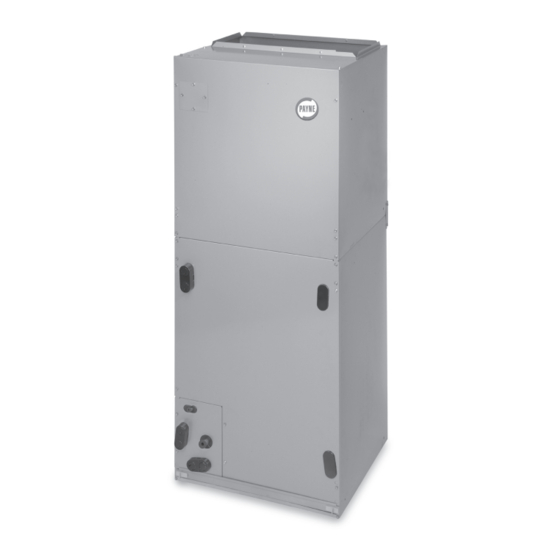
Model PF4MNB Fan Coils are designed for flexibility and can be
used for upflow, horizontal, or downflow (kit required) and
manufactured and mobile home applications. These units are
designed to meet the low air leak requirements currently in effect.
Because of this, the units need special attention in the condensate
pan and drain connection area and when brazing tubing. These
units are designed specifically for R- -410A refrigerant and must be
used only with R- -410A refrigerant air conditioners and heat
pumps as shipped. These units are available for systems of 18,000
through
60,000
Factory- -authorized, field- -installed electric heater packages are
available in sizes 5 through 30kW. See Product Data literature for
available accessory kits.
.
HEATER PACKAGES
Factory- -approved, field- -installed, UL listed heater packages are
available from your equipment supplier. See unit rating plate for a
list of factory- -approved heaters. Heaters that are not factory
approved could cause damage which would not be covered under
the equipment warranty.
SIZES 019 TO 061
WARNING
CAUTION
INTRODUCTION
Btuh
nominal
cooling
capacity.
Advertisement
Table of Contents

Subscribe to Our Youtube Channel
Related Manuals for Carrier PF4MNB 019


Summary of Contents for Carrier PF4MNB 019
-
Page 1: Table Of Contents
‘ PF4MNB FOR R410A REFRIGERANT SIZES 019 TO 061 DIRECT EXPANSION FAN COIL UNIT Installation Instructions NOTE: Read the entire instruction manual before starting the Understand the signal words DANGER, WARNING, and CAUTION. These words are used with the safety- -alert symbol. installation. -
Page 2: Step 1 - Check Equipment
INSTALLATION CAUTION Step 1 — Check Equipment Unpack unit and move to final location. Remove carton taking care UNIT OR PROPERTY DAMAGE HAZARD not to damage unit. Inspect equipment for damage prior to Failure to follow this caution may result in product or property installation. - Page 3 6. Make sure the pan cap in the fitting door is properly seated on the fitting door to retain the low air leak rating of the COIL unit. FA CT OR Y SHIPPED BRACKET HORIZONTAL LEFT APPLICATION 7. Add gaskets from kit KFAHD per kit instructions. COI L SUPPORT RAIL...
-
Page 4: Step 3 - Air Ducts
b. If fan coil is against wall, secure fan coil to wall stud DRAIN PAN DRAIN PAN SUPPORT BRACKET SUPPORT BRACKET using 1/8- -in (3 mm) thick right- -angle brackets. Attach brackets to fan coil using no. 10 self- -tapping screws and to wall stud using 5/16- -in. - Page 5 CAUTION FAN COIL THERMOSTAT PROPERTY DAMAGE HAZARD Failure to follow this caution may result in product or property damage. If a disconnect switch is to be mounted on unit, select a location where drill or fastener will not contact electrical or refrigerant components.
- Page 6 FAN COIL THERMOSTAT HEAT PUMP HEAT PUMP THERMOSTAT (CONTROL) FAN COIL (CONTROL) ODTS ODTS A09388 A09386 Fig. 14 - - Wiring Layout Heat Pump Unit Fig. 12 - - Wiring Layout Heat Pump Unit (Cooling and 2- -Stage Heat for Manufactured Housing) (Cooling and 2- -Stage Heat with 1 Outdoor Thermostat) Transformer Information FAN COIL...
-
Page 7: Step 5 - Refrigerant Tubing Connection And Evacuation
When 2 stages are desired, cut W3 at the W2 wire nut, strip and reconnect per the thermostat kit instruction. (See Fig. 12.) When 3 stages are desired, cut the W2 wire nut off and discard. Strip W2, W3, and E and reconnect per thermostat kit instructions. (See Fig. 13.) NOTE: When 3 stages are used or anytime the E terminal is not 1 2 3 4 5... -
Page 8: Step 7 - Condensate Drains
CAUTION UNIT PRODUCT DAMAGE HAZARD Failure to follow this caution may result in product or property 2” MIN damage. (51 mm) Wrap a wet cloth around rear of fitting to prevent damage to TXV and factory- -made joints. 2” MIN (51 mm) Step 6 —... -
Page 9: Step 8 - Accessories
Step 9 — Sequence of Operation alternative to using an external condensate pan, some localities may allow the use of a separate 3/4- -in (19 mm) condensate line A. Continuous Fan (with appropriate trap) to a place where the condensate will be Thermostat closes R to G. -
Page 10: Airflow Performance Tables
EXTERNAL STATIC (in. wc) MODEL & SIZE BLOWER SPEED 0.10 0.20 0.30 0.40 0.50 0.60 Tap 5 Tap 4 Tap 3 PF4MNB 019 Tap 2 Tap 1 Tap 5 Tap 4 Tap 3 PF4MNB 025 Tap 2 Tap 1 Tap 5 1189 1151... - Page 11 AIRFLOW PERFORMANCE TABLES (cont.) Table 2 – Air Delivery Performance Correction Component Pressure Drop (in. wc) at Indicated Airflow (Dry to Wet Coil) SIZE 1000 1100 1200 1300 1400 1500 1600 1700 1800 1900 2000 0.034 0.049 0.063 --- --- --- --- --- --- --- ---...
-
Page 12: R- -410A Quick Reference Guide
R- -410A QUICK REFERENCE GUIDE R- -410A refrigerant operates at 50- -70 percent higher pressures than R- -22. Be sure that servicing equipment and replacement components are designed to operate with R- -410A refrigerant. R- -410A refrigerant cylinders are rose colored. Recovery cylinder service pressure rating must be 400 psig, DOT 4BA400 or DOT BW400.
Need help?
Do you have a question about the PF4MNB 019 and is the answer not in the manual?
Questions and answers