Table of Contents
Advertisement
Available languages
Available languages
Zoeller
is a registered trademark
®
of Zoeller Co. All Rights Reserved.
ATTACH YOUR RECEIPT HERE
Serial Number
Questions, problems, missing parts? Before returning to your retailer, call our customer
service department at 1-800-584-8089, 7:30 a.m. - 5:00 p.m., EST, Monday - Friday.
Purchase Date
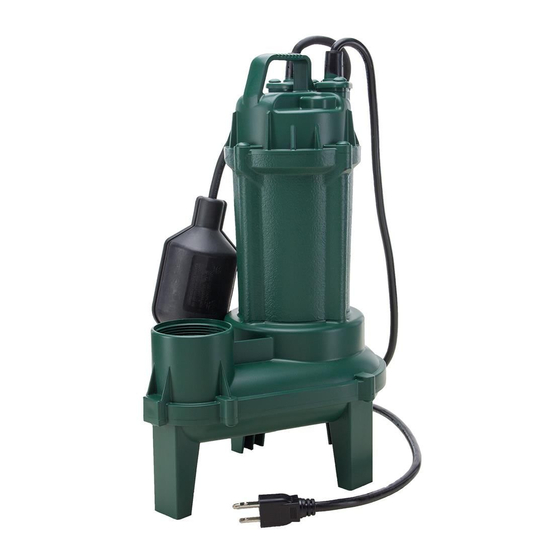
SEWAGE PUMP
1
MODEL #1261-0001
Español p. 14
SW1134 B
Advertisement
Table of Contents

Subscribe to Our Youtube Channel
Related Manuals for Zoeller 1261-0001


Summary of Contents for Zoeller 1261-0001
- Page 1 SEWAGE PUMP MODEL #1261-0001 Zoeller is a registered trademark ® of Zoeller Co. All Rights Reserved. Español p. 14 ATTACH YOUR RECEIPT HERE Purchase Date Serial Number Questions, problems, missing parts? Before returning to your retailer, call our customer service department at 1-800-584-8089, 7:30 a.m. - 5:00 p.m., EST, Monday - Friday.
-
Page 2: Safety Information
SAFETY INFORMATION Please read and understand this entire manual before attempting to assemble, operate, or install the product. • NOTE: Pumps with the “UL” Mark and pumps with the “US” mark are tested to UL Standard UL778. CSA certified pumps are certified to CSA Standard C22.2 No. 108. (CUS.) DANGER •... -
Page 3: Package Contents
CAUTION • PRODUCT DAMAGE MAY RESULT. Make certain that the power source conforms to the requirements of your equipment. • PRODUCT DAMAGE MAY RESULT. Maximum continuous operating water temperature for standard model pumps must not exceed 104°F (40°C). PACKAGE CONTENTS Description Quantity Pump... -
Page 4: General Pump Information
“on” level. 3. The pump will turn off automatically when the water level in the basin reaches the “off” level. Item On Level Off Level 1261-0001 14 in. 9 in. -
Page 5: Installation Instructions
INSTALLATION INSTRUCTIONS 1. Use a basin (not included) that is at least 18 in. wide by 30 in. deep. 30 in. 18 in. 2. Clean the basin of all debris. 3. Set the pump on a solid, level surface. A brick or block (not included) may be installed under the pump to provide a solid base. - Page 6 INSTALLATION INSTRUCTIONS 4. Place the pump inside the basin with the switch positioned away from incoming water. Incoming water Switch 5. Be sure the float switch is at least 1 in. away from the side walls of the basin and free of any obstructions through the full range of switch motion.
-
Page 7: Discharge Pipe
INSTALLATION INSTRUCTIONS 7. Use a 2-step PVC glue system (not included) to join pipe and any fittings needed. 8. Drill a 3/16 in. hole in the discharge pipe above the pump discharge to prevent air lock. Water stream will be visible from this hole when the pump is running. The Discharge hole must be cleaned periodically. - Page 8 INSTALLATION INSTRUCTIONS 10. Install a 2 in. check valve (not included) above the union to prevent back-flow. Check Valve 11. Install a 2 in. gate valve (not included) above the check Gate valve as required by local, regional or state codes. Valve 12.
- Page 9 INSTALLATION INSTRUCTIONS 13. Attach power supply cord to discharge pipe using cable or zip ties (not included) to allow the float switch to move freely. Cable or Zip Ties 14. Connect pump power supply cord to a receptacle GFCI protected by a ground fault circuit interruptor (GFCI). protected receptacle 15.
-
Page 10: Specifications
Vent pipe SPECIFICATIONS MOTOR DATA CHART Locked Rotor Phase Volts Code Letter Max Amps Amps 19.5 PERFORMANCE Item Shut Off Discharge Ft. of Head Flow (GPM) Head (Ft.) Size Number 1261-0001 2 in. -
Page 11: Troubleshooting
TROUBLESHOOTING Problem Possible Cause Corrective Action Pump will not 1. Water level too low. 1. Water must be at the appropriate level start or run. to activate switch. 2. Blown fuse or tripped circuit breaker. 2. If blown, determine cause and then either replace with properly sized fuse, or reset breaker. -
Page 12: Care And Maintenance
TROUBLESHOOTING Problem Possible Cause Corrective Action Pump operates, 1. Low line voltage. 1. Contact an electrician. but delivers little 2. Inlet screen clogged. 2. Remove debris. or no water. 3. Broken impeller or debris in impeller 3. Remove screen and volute, clean cavity. - Page 14 BOMBA PARA AGUAS NEGRAS MODELO #1261-0001 Zoeller es una marca registrada ® de Zoeller Co. Todos derechos reservados. ADJUNTE SU RECIBO AQUÍ Fecha de compra Número de serie ¿Preguntas, problemas, partes faltantes? Antes de acudir al minorista, llame a nuestro departamento de servicio al cliente al 1-800-584-8089, de lunes a viernes de 7:30 a.m.
-
Page 15: Información De Seguridad
INFORMACIÓN DE SEGURIDAD Lea y comprenda completamente este manual antes de intentar ensamblar, usar o instalar el producto. • NOTA: Las bombas con la marca “UL” y con la marca “US” se prueban para cumplir los estándares de UL UL778. Las bombas con certificación CSA cumplen con el estándar CSA C22.2 No. 108. (CUS.) PELIGRO •... -
Page 16: Contenido Del Paquete
PRECAUCIÓN • ALERTA DE DESCARGA ELÉCTRICA. Compruebe que el circuito de suministro de energía eléctrica de la bomba esté equipado con fusibles o cortacircuitos de la capacidad adecuada. Es aconsejable usar un circuito derivado independiente con la capacidad estipulada en el Código eléctrico nacional de EE.UU. (National Electrical Code) según la corriente especificada en la placa de identificación de la bomba. - Page 17 Nivel de encendido 3. La bomba se apagará automáticamente cuando el nivel de agua en el recipiente alcance el nivel de apagado. Nivel de Nivel de Nivel de Artículo encendido apagado encendido 1261-0001 14 pulg. 9 pulg.
-
Page 18: Instrucciones De Instalación
INSTRUCCIONES DE INSTALACIÓN 1. Se un recipiente (no se incluye) que sea de al menos 45,72 cm de ancho por 76,20 cm de profundidad. 76,20 45,72 cm 2. Elimine todos los desechos del recipiente. 3. Fije la bomba en una superficie sólida y nivelada. Puede instalar un ladrillo o bloque (no se incluye) debajo de la bomba para proporcionar una base sólida. - Page 19 INSTRUCCIONES DE INSTALACIÓN 4. Coloque la bomba dentro del recipiente con el interruptor ubicado lejos del agua entrante. Agua entrante Interruptor 5. Asegúrese de que el interruptor del flotador esté por lo menos a 25 mm (1”) de las paredes laterales del contenedor para agua y libre de obstrucciones en todo el rango de movimiento del interruptor.
- Page 20 INSTRUCCIONES DE INSTALACIÓN 7. Use un sistema de adhesivo PVC de 2 pasos (no se incluye) para unir la tubería y cualquier conector necesario. 8. Taladre un orificio de 4,76 mm en el tubo de descarga sobre la descarga de la bomba para evitar obstrucciones de aire. El chorro de agua será...
- Page 21 INSTRUCCIONES DE INSTALACIÓN 10. Instale una válvula de control de 2 pulg (no se incluye) sobre la unión para evitar el reflujo. Válvula de control 11. Instale una válvula de compuerta de 2 pulg (no se incluye) Válvula de sobre la válvula de control según lo requieran los códigos compuerta locales, regionales y estatales.
- Page 22 INSTRUCCIONES DE INSTALACIÓN 13. Fije el cable de suministro de electricidad al tubo de descarga con el cable o un amarracables (no se incluye) para permitir que el interruptor de flotador se mueva libremente. Cable o un amarracables 14. Conecte el cable de suministro de electricidad de la bomba a un tomacorriente protegido por un interruptor de circuito Tomacorriente de falla de puesta a tierra (GFCI, por sus siglas en inglés).
-
Page 23: Especificaciones
Tubo de ventilación ESPECIFICACIONES TABLA DE DATOS DEL MOTOR Letra Amperaje Amperaje del Fase Voltios código máximo rotor bloqueado 19.5 RENDIMIENTO Número de Pies de Cabezal de Tamaño de Flujo (GPM) artículo cabezal cierre (pies) descarga 1261-0001 2 in. -
Page 24: Solución De Problemas
SOLUCIÓN DE PROBLEMAS Problema Causa Posible Correción del Defecto La bomba no 1. Water level too low. 1. El nivel de agua es demasiado bajo. enciende ni 2. Se fundió un fusible o el interruptor de 2. Si está fundido, determine la causa y funciona. -
Page 25: Cuidado Y Mantenimiento
SOLUCIÓN DE PROBLEMAS Problema Causa Posible Correción del Defecto La bomba funciona 1. El voltaje de línea es bajo. 1. Póngase en contacto con un electricista. pero sale muy 2. La malla de entrada está tapada. 2. Retire los desechos. poca o nada de 3. - Page 26 GARANTÍA Este producto se garantiza por un período de dos años a partir de la fecha de compra o treinta (30) meses a partir de la fecha de fabricación, lo que ocurra primero. Sujeto a las condiciones indicadas a continuación, el fabricante se compromete a reparar o reemplazar al consumidor original cualquier parte del producto que resulte defectuosa debido a defectos de materiales o mano de obra.
Need help?
Do you have a question about the 1261-0001 and is the answer not in the manual?
Questions and answers