Table of Contents
Advertisement
Zoeller
is a registered trademark
®
of Zoeller Co. All Rights Reserved.
ATTACH YOUR RECEIPT HERE
Serial Number
Questions, problems, missing parts? Before returning to your retailer, call our customer
service department at 1-800-584-8089, 7:30 a.m. - 5:00 p.m., EST, Monday - Friday.
Purchase Date
1
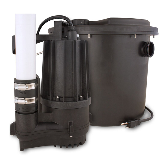
DRAIN PUMP
MODEL #1104-0082
Español p. 19
Pump and check valve
preassembled in basin
Advertisement
Table of Contents

Related Manuals for Zoeller 1104-0082


Summary of Contents for Zoeller 1104-0082
- Page 1 DRAIN PUMP MODEL #1104-0082 Zoeller is a registered trademark ® Español p. 19 of Zoeller Co. All Rights Reserved. Pump and check valve preassembled in basin ATTACH YOUR RECEIPT HERE Purchase Date Serial Number Questions, problems, missing parts? Before returning to your retailer, call our customer...
-
Page 2: Safety Information
SAFETY INFORMATION Please read and understand this entire manual before attempting to assemble, operate or install the product. • NOTE: Pumps with the “UL” mark and pumps with the “US” mark are tested to UL Standard UL778. CSA certified pumps are certified to CSA Standard C22.2 No. 108. (CUS.) DANGER •... -
Page 3: Package Contents
CAUTION • PRODUCT DAMAGE MAY RESULT Make certain the power source conforms to the requirements of your equipment. • PRODUCT DAMAGE MAY RESULT Maximum continuous operating water temperature for standard model pumps must not exceed 110°F (43°C). • PRODUCT DAMAGE MAY RESULT Do not use an automatic plumbing vent device such as a “Pro-Vent.”... - Page 4 PREPARATION Before beginning installation of product, make sure all parts are present. Compare parts with package contents list. If any part is missing or damaged, do not attempt to assemble the product. Estimated Installation Time: 2 hours Tools Required for Assembly (not included): tape measure, pipe tape, hacksaw, flathead screwdriver, 2-step PVC glue system (primer and sealer).
-
Page 5: Installation Instructions
3. Softener discharge pump Vent Pipe Discharge Pipe Water Softener Inlet Pipe 4. Dehumidifier pump Vent Pipe Discharge Pipe Inlet Pipe INSTALLATION INSTRUCTIONS 1. Thread 2 in. coupling (not included) into the vent opening on the top of the pre-assembled pump system. - Page 6 2. Thread 1-1/2 in. coupling (not included) into the discharge opening at the top of the pre-assembled pump system. Discharge Opening 3. Attach rigid 2 in. vent pipe (not included) to the vent pipe coupling according to local, regional, and state codes. 4.
- Page 7 5. Thread compression fitting (not included) onto 1-1/4 in. drain pipe (not included). Insert drain pipe into the inlet opening on the side of the pre-assembled pump system and tighten fitting. INSTALLATION INSTRUCTIONS FOR SMALL SPACES 1. For areas where space does not allow for standard installation, pre-assembled pump system can be installed directly under a sink using an internal trap (not included).
- Page 8 3. Cut a tailpipe (not included) to the total pipe length in step 2. (4 in. min.) Tailpipe Length 4-1/2 in. 4. Unscrew 8 bolts from top of pre-assembled pump system and remove cord seal (F) and basin lid (E). 5.
- Page 9 6. Attach trap components to the underside of the basin lid (E). Make sure the trap height is at least 4 inches to Vent Inlet ensure a proper water seal. Discharge Flanged Tailpipe Trap Trap Detail 4 in. Min. 7. Thread 1-1/4 in. compression fitting (not included) onto the tailpipe from step 3.
- Page 10 9. Apply pipe tape (not included) to all threaded connections, and a 2-step PVC glue system (not included) to non-threaded connections. 10. Place the basin lid (E)/trap assembly from step 7 on top of the basin (B), making sure the foam gasket (H) is firmly in place.
- Page 11 12. Thread 2 in. coupling (not included) into the vent opening on the top of the basin (B). 13. Thread 1-1/2 in. coupling (not included) into the discharge opening at the top of the basin (B). 14. Attach rigid 2 in. vent pipe (not included) to the vent pipe coupling according to local, regional, and state codes.
- Page 12 15. Attach rigid 1-1/2 in. discharge pipe (not included) to the discharge pipe coupling according to local, regional, and state codes. Plumb into existing drain pipe per local, regional, and state codes. Use additional check valve (not included) as required by codes.
- Page 13 TESTING 1. Connect remaining discharge pipe into main waste Main line to sewer or septic tank. Connect inlet piping as Waste Line required for the installation and connect vent pipe according to local, regional, and state codes. Use additional check valve (not included) as required by Vent Pipe Discharge Pipe codes.
-
Page 14: Troubleshooting
TROUBLESHOOTING Problem Possible Cause Corrective Action Pump will not 1. Blown fuse or tripped circuit breaker. 1. If blown, determine cause and then start or run. either replace with properly sized fuse or reset breaker. 2. Low line voltage. 2. Contact an electrician. 3. -
Page 15: Specifications
3. Remove base and inspect. damaged impeller or pump housing. SPECIFICATIONS MOTOR DATA CHART Locked Rotor Phase Volts Code Letter Max Amps Amps PERFORMANCE Item Shut Off Discharge Ft. of Head Flow (GPM) Head (Ft.) Size Number 1104-0082 1-1/2 in. -
Page 16: Care And Maintenance
CARE AND MAINTENANCE WARNING: Always disconnect pump from power supply before handling. Inspect and test system for proper operation at least every three months. 1. Remove any build-up of debris from the switch or float, and check to be sure it moves freely. Debris on Float 2. -
Page 17: Warranty
WARRANTY This product is warranted for one (1) year from the date of purchase or two (2) years from the date of manufacture, whichever occurs first. Subject to the conditions hereinafter set forth, the manufacturer will repair or replace to the original consumer, any portion of the product which proves defective due to defective materials or workmanship. -
Page 18: Replacement Parts List
REPLACEMENT PARTS LIST For replacement parts, call our customer service department at 1-800-584-8089, 8 a.m. - 8 p.m., EST, Monday - Friday. PART DESCRIPTION PART NO. Basin 013017 Pump 152289A Check Valve 019768 Basin Lid 013018 Cord Seal 006018...
Need help?
Do you have a question about the 1104-0082 and is the answer not in the manual?
Questions and answers
Need a new foam gasket for model 1104-0082 sump pump