Table of Contents
Advertisement
Quick Links
ZoellerAtHome.com
ZoellerAtHome.com
Zoeller
is a registered trademark
®
of Zoeller Co. All Rights Reserved.
ATTACH YOUR RECEIPT HERE
Serial Number
Questions, problems, missing parts? Before returning to your retailer, call our customer
service department at 1-800-584-8089, 7:30 a.m. - 5:00 p.m., EST, Monday - Friday.
Purchase Date
1
© 2020. All rights reserved.
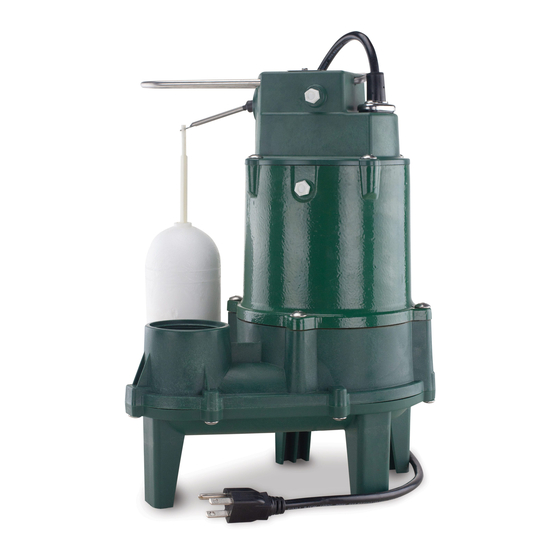
SEWAGE PUMP
SEWAGE PUMP
MODEL #1263
MODEL #1263-0001Q
Español p. 17
SW1316 B
Advertisement
Table of Contents

Related Manuals for Zoeller 1263-0001Q


Summary of Contents for Zoeller 1263-0001Q
- Page 1 ZoellerAtHome.com MODEL #1263 Zoeller is a registered trademark MODEL #1263-0001Q ® of Zoeller Co. All Rights Reserved. Español p. 17 ATTACH YOUR RECEIPT HERE Serial Number Purchase Date Questions, problems, missing parts? Before returning to your retailer, call our customer service department at 1-800-584-8089, 7:30 a.m.
-
Page 2: Safety Information
SAFETY INFORMATION SAFETY INFORMATION Please read and understand this entire manual before attempting to assemble, operate, or install the Please read and understand this entire manual before attempting to assemble, operate, or install the product. product. • • NOTE: Pumps with the “UL” Mark and pumps with the “US” mark are tested to UL Standard NOTE: Pumps with the “UL”... -
Page 3: Package Contents
CAUTION • PRODUCT DAMAGE MAY RESULT. Make certain that the power source conforms to the requirements of your equipment. • PRODUCT DAMAGE MAY RESULT. Maximum continuous operating water tem per a ture for stan dard mod el pumps must not exceed 104°F (40°C). -
Page 4: General Pump Information
GENERAL PUMP INFORMATION 1. Sewage pumps are pumps used to remove 2 in. Discharge Upper level drainage waste water that contains solids up to 2 in. pipe Cleanout in diameter. The most common application is Main waste line to sewer for draining bathroom waste water to a sewer or septic tank Vent pipe... -
Page 5: Installation Instructions
INSTALLATION INSTRUCTIONS 1. Use a basin (not included) that is at least 18 in. wide by 30 in. deep. 30 in. 18 in. 2. Clean the basin of all debris. 3. Set the pump on a solid, level surface. A brick or block (not included) may be installed under the pump to provide a solid base. - Page 6 INSTALLATION INSTRUCTIONS 4. Place the pump inside the basin with the switch positioned away from incoming water. Incoming water Switch 5. Be sure the fl oat switch is at least 1 in. away from the side walls of the basin and free of any obstructions through the full range of switch motion.
- Page 7 INSTALLATION INSTRUCTIONS 7. Use a 2-step PVC glue system (not included) to join pipe and any fi ttings needed. 8. Drill a 3/16 in. hole in the discharge pipe above the pump discharge to prevent air lock. Pumps have a vent located in the pump, but an additional vent hole Discharge is recommeded.
- Page 8 INSTALLATION INSTRUCTIONS 10. Install a 2 in. check valve (not included) above the union to prevent back-fl ow. Check Valve 11. Install a 2 in. gate valve (not included) above the check Gate valve as required by local, regional or state codes. Valve 12.
- Page 9 INSTALLATION INSTRUCTIONS 13. Attach power supply cord to discharge pipe using cable or zip ties (not included) to allow the fl oat switch to move freely. Cable or Zip Ties 14. Connect pump power supply cord to a receptacle GFCI protected by a ground fault circuit interruptor (GFCI).
-
Page 10: Specifications
INSTALLATION INSTRUCTIONS 16. Install a basin cover and gasket (not included) on the top of the basin. This will contain gases and odors, prevent debris from falling into the basin, and prevent personal injury. Basin cover and gasket 17. Install a vent pipe (not included) according to local, regional, or state codes to remove gases and odors. -
Page 11: Troubleshooting
TROUBLESHOOTING Problem Possible Cause Corrective Action Pump will not 1. Water level too low. 1. Water must be at the appropriate level start or run. to activate switch. 2. Blown fuse or tripped circuit breaker. 2. If blown, determine cause and then either replace with properly sized fuse, or reset breaker. -
Page 12: Care And Maintenance
TROUBLESHOOTING Problem Possible Cause Corrective Action Pump operates, 1. Low line voltage. 1. Contact an electrician. but delivers little 2. Inlet screen clogged. 2. Remove debris. or no water. 3. Broken impeller or debris in impeller 3. Remove screen and volute, clean cavity. -
Page 13: Warranty
WARRANTY This product is warranted for three years from the date of purchase. Subject to the conditions hereinafter set forth, the manufacturer will repair or replace to the original consumer, any portion of the product which proves defective due to defective materials or workmanship. To obtain warranty service, contact the dealer from whom the product was purchased. -
Page 14: Repair Parts
REPAIR PARTS MODEL ITEM DESCRIPTION 1263 Cord Kit 025390 Includes cord w/o-ring, case o-ring (115x4 NBR), clamp screws (M5-0.8x16), cap screws (M6-1.0x15), GND screw (M4-0.7x6.0) Capacitor Kit Includes capacitor, cap screws (M6-1.0x15), mounting screw (M4- 025383 0.7x6), case o-ring (115x4 NBR) Base Kit 025388 Includes pump base, screws (M5-0.8x15) -
Page 15: Wiring Diagram
WIRING DIAGRAM BLACK SWITCH FLOAT BLACK GREEN WHITE WHITE CAPACITOR BLACK WHITE BLUE BLUE YELLOW MOTOR O.L. START © 2020. All rights reserved. - Page 16 © 2020. All rights reserved.
Need help?
Do you have a question about the 1263-0001Q and is the answer not in the manual?
Questions and answers