
Related Manuals for Federal Signal Corporation IPX6 IMPAXX


Summary of Contents for Federal Signal Corporation IPX6 IMPAXX
- Page 1 IPX6 IMPAXX Light Heads ® Installation and Maintenance Manual 2562654C REV. C2 0320 Printed in U.S.A. © Copyright 2011-2020 Federal Signal Corporation...
- Page 2 A copy of this limited warranty can also be obtained by written re- quest to Federal Signal Corporation, 2645 Federal Signal Drive, University Park, IL 60484, email to info@fedsig.com or call +1 708-534-3400.
-
Page 3: Table Of Contents
Contents Safety Messages................5 Safety Messages to Installers and Service Personnel of Warning Light Equipment ............5 Safety Message to Operators of Warning Lights ....9 Unpacking the Product ..............10 An Overview of the IPX600 Series ..........10 Installing the IPX600 LED Light Heads .......... 12 Converting a Light Head from Controller to Follower and Vice Versa .................... - Page 4 Figures Figure 1 IPX600 mounted with bezel ..........19 Figure 2 IPX600 mounted without bezel ........20 Figure 3 Wiring for synchronized lights ........22 Figure 4 Wiring for alternating lights ..........23 Figure 5 X-pattern wiring diagram ..........23 Tables Table 1 Package contents .............
-
Page 5: Safety Messages
Safety Messages Safety Messages Safety Messages to Installers and Service Personnel of Warning Light Equipment People’s lives depend on your proper installation and servicing of Federal Signal products. It is important to read and follow all instructions shipped with this product. Listed below are some other important safety instructions and precautions you should follow: Before Installation or Service... - Page 6 Safety Messages Electrical Hazards • Strobe systems present a shock hazard because they use high voltage to operate. Do not handle strobe cables, the power supply, or bulbs or remove the lens while the equipment is connected. Strobe systems can also hold their charge even after they have been turned off.
- Page 7 Safety Messages the radio noise emitted from the lighting system to interfere with the reception of the radio transmitter and reduce radio reception. • Do not attempt to wash any unsealed electrical device while it is connected to its power source. During Installation and Service •...
- Page 8 Safety Messages • Refer to the manual packed with the lighting system for proper electrical connections, additional precautions and information. • Locate the light system controls so the VEHICLE and CONTROLS can be operated safely under all driving conditions. After Installation or Service •...
-
Page 9: Safety Message To Operators Of Warning Lights
Safety Messages Safety Message to Operators of Warning Lights People’s lives depend on your safe use of our products. Listed below are some important safety instructions and precautions you should follow: • Do not attempt to activate or deactivate the light system control while driving in a hazardous situation. -
Page 10: Unpacking The Product
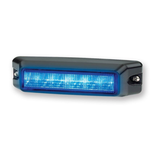
Unpacking the Product • Operate your vehicle and its light/sound system in accordance with your department’s Standard Operating Procedures. • If a selected function does not perform properly or if any of the lamps remain illuminated when the control is off, disconnect the power connector from the control unit and contact the nearest service center. - Page 11 An Overview of the IPX600 Series various combinations of amber, blue, green, red, or white with a clear lens. The IPX600 can also be ordered with colored lenses matching the LED color (for single-color lights only). LEDs are available in enhanced horizontal and vertical off-axis or focused configurations.
-
Page 12: Installing The Ipx600 Led Light Heads
Installing the IPX600 LED Light Heads Installing the IPX600 LED Light Heads LIGHT HAZARD: To be an effective warning device, an emergency warning system produces bright light that can be hazardous to your eyesight when viewed at a close range. Do not stare directly into this lighting product at a close range, or permanent damage to your eyesight may occur. -
Page 13: Converting A Light Head From Controller To Follower And Vice Versa
Converting a Light Head from Controller to Follower and Vice Versa Converting a Light Head from Controller to Follower and Vice Versa Several IPX600 light heads can be controlled through the selected flash pattern of one controller light head. All IPX600 light heads are shipped as controllers. -
Page 14: Converting A Light Head From Follower To Controller
Converting a Light Head from Controller to Follower and Vice Versa Changing from controller to follower resets all features to the default settings. See Table 2 for the defaults. The light head will shortly go to a low-power steady burn with all LEDs regardless of which color lights up. -
Page 15: Configuring Multicolor Light Heads
Configuring Multicolor Light Heads Configuring Multicolor Light Heads The IPX600 can be ordered in various color combinations, which flash differently, depending on what colors are ordered. By default, the OPTION wire is set to steady burn a single color by applying 12 Vdc (+BAT) to it. The OPTION wire can be changed to instead control white LED flashing instead of steady burn. -
Page 16: Setting The Steady-Burn Color
Configuring Multicolor Light Heads To set the white LEDs to always flash: 1. Connect the black wire from the light head to ground (–GND). 2. Apply 12 Vdc (+BAT) to the red wire from the light head. 3. Hold the green pattern-selection wire to ground (–GND) until the light head goes out and then flashes four times. -
Page 17: Setting A Multicolor Light Head To Flash One Color
Mounting the IPX600 Light Head to a Vehicle Setting a Multicolor Light Head to Flash One Color To change the from multicolor to one color: 1. Connect the black wire from the light head to ground (–GND). 2. Apply 12 Vdc (+BAT) to the red wire from the light head. 3. -
Page 18: Mounting The Ipx600 Light Head To A Vehicle
Mounting the IPX600 Light Head to a Vehicle Mounting the IPX600 Light Head to a Vehicle ROOF SUPPORT STRUCTURE: There is a roof support piece that spans the distance between the driver side and passenger side. DO NOT DRILL THROUGH THIS PIECE! Adjust any hole locations until the holes can be drilled without going through this support. -
Page 19: Figure 1 Ipx600 Mounted With Bezel
Mounting the IPX600 Light Head to a Vehicle DRILLING PRECAUTIONS: When drilling holes, check the area you are drilling into to ensure that you do not damage vehicle components while drilling. All drilled holes should be de-burred, and all sharp edges should be smoothed. All wire routings going through drilled holes should be protected by a grommet or convolute/split loom tubing. -
Page 20: Mounting The Light Head Without The Bezel
Mounting the IPX600 Light Head to a Vehicle Mounting the Light Head Without the Bezel LEAK PATH CREATION: The use of user-supplied mounting hardware may create a leak path that causes moisture damage to the IPX600 light. An improperly mounted IPX600 is not eligible for the warranty. -
Page 21: Wiring The Ipx600 Light Head In The Vehicle
Wiring the IPX600 Light Head in the Vehicle Wiring the IPX600 Light Head in the Vehicle WIRING PRECAUTION: Never attach both the orange wire AND the yellow wire from the CONTROLLER light head to the same FOLLOWER light head. Connecting both signal wires to the same FOLLOWER will cause the light heads to malfunction. -
Page 22: Synching And Alternating Light Heads
Selecting a Flash Pattern will flash once almost immediately after you tap the green pattern-selection wire; after this flash, remove ground (–GND). 2. To reverse the direction of pattern selection, hold the green wire to ground (–GND) for slightly longer than 1 second but less than 3 seconds. -
Page 23: Configuring Light Heads For An X Flash Pattern
Selecting a Flash Pattern Figure 4 Wiring for alternating lights 12 Vdc (+BAT) Fuse* Steady Burn / Power Flash White (Optional) Synchronized Orange Orange Controller Follower White White Light Head Light Head Black Black *Fuse Requirements: 1 To 3 Light Heads = 5 A (–GND) 4 To 6 Light Heads = 10 A Steady Burn Pulls 1 A... -
Page 24: Table 3 Flash Patterns For The Ipx600 Led Light Head
Selecting a Flash Pattern Table 3 Flash patterns for the IPX600 LED light head Flash Flash Description Description Pattern Pattern Null (off) 75 FPM Double 79 FPM Power Quad* 150 FPM Triple 150 FPM Single 75 FPM Triple 151 FPM Single 5 Single at 680 FPM 4 Single at 216 FPM 74 FPM Single*... -
Page 25: Maintaining The Light Heads
Maintaining the Light Heads Maintaining the Light Heads Periodically cleaning the IPX600 lenses using proper procedures and compatible cleaners will prolong their service life. There are no user-serviceable parts within the light head. However, you can order replacements for the mounting hardware listed in Table 4 on page 27. -
Page 26: Testing The System
Test the vehicle only in a controlled environment. Getting Technical Support and Service For technical support and service, please contact: Service Department Federal Signal Corporation Phone: 1-800-433-9132 Email: empserviceinfo@fedsig.com IMPAXX IPX600 Series LED Light Heads ®... -
Page 27: Getting Repair Service
(RMA). Obtain a RMA from a local Distributor or Manufacturer’s Representative. Provide a brief explanation of the service requested, or the nature of the malfunction. Address all communications and shipments to the following: Federal Signal Corporation Service Department 2645 Federal Signal Drive University Park, IL 60484-3167 Ordering Replacement Parts To order replacement parts, call Customer Support at 1-800-264-3578, 7 a.m. - Page 28 2645 Federal Signal Drive University Park, Illinois 60484 www.fedsig.com Customer Support Police/Fire-EMS: 800-264-3578 • +1 708 534-3400 Work Truck: 800-824-0254 • +1 708 534-3400 Technical Support 800-433-9132 • +1 708 534-3400...
Need help?
Do you have a question about the IPX6 IMPAXX and is the answer not in the manual?
Questions and answers