
Related Manuals for Federal Signal Corporation CN SignalMaster


Summary of Contents for Federal Signal Corporation CN SignalMaster
- Page 1 CN SignalMaster ™ Installation, Maintenance, and Service Manual 25500013 REV. B1 0220 Printed in U.S.A. © Copyright 2016-2020 Federal Signal Corporation...
- Page 2 This product is subject to and covered by a limited warranty, a copy of which can be found at www.fedsig.com/SSG-Warranty. A copy of this limited war- ranty can also be obtained by written request to Federal Signal Corporation, 2645 Federal Signal Drive, University Park, IL 60484, email to info@fedsig.com or call +1 708-534-3400.
-
Page 3: Table Of Contents
Ordering Replacement Parts ........................19 Tables Table 1 Mounting kit contents ...........................9 Table 2 CN SignalMaster controls and wires from the Serial Interface Module........ 12 Table 3 CN SignalMaster DIP switch settings ..................... 13 Table 4 Common replacement parts ......................19 Figures Figure 1 Mounting brackets attached to CN SignalMaster .............. -
Page 4: Safety Messages For Installers And Service Personnel
Safety Messages for Installers and Service Personnel For your safety, read and understand this manual thoroughly before installing, operating, and servicing the CN SignalMaster ™ . The safety messages presented in this section and throughout the manual are reminders to exercise extreme care at all times. - Page 5 Safety Messages for Installers and Service Personnel terminal, and a suitable fuse should be installed on the positive battery terminal connection as close to the battery as possible. Ensure that all wires and fuses are rated to handle the device and system amperage requirements. •...
- Page 6 • File these instructions in a safe place and refer to them when maintaining and/or reinstalling the product. Failure to follow all safety precautions and instructions may result in property damage, serious injury, or death. RETAIN AND REFER TO THIS MESSAGE CN SignalMaster ™ Federal Signal www.fedsig.com...
-
Page 7: Safety Messages For Operators Of Warning Lights
Safety Messages for Operators of Warning Lights Safety Messages for Operators of Warning Lights People’s lives depend on your safe use of our products. Listed below are some important safety instructions and precautions you should follow. • Do not attempt to activate or deactivate the light system control while driving in a hazardous situation. -
Page 8: An Overview Of The Cn Signalmaster
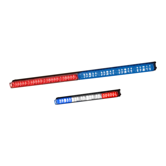
LEDs, eliminating the loss of primary warning colors in takedown and directional warning positions. Individual CN SignalMaster lightheads can flash between red, blue, amber, or white. The light bar operates at a nominal input of 13.6 Vdc (11 Vdc minimum) and an operating temperature range of –30°C to +65°C. -
Page 9: Installing The Cn Signalmaster
To mount the light bar: 1. Determine the appropriate spacing of the mounting holes for your application. 2. Install the mounting brackets to the CN SignalMaster with two #10 6-lobe screws per bracket. See Figure 1 on page page 10. -
Page 10: Wiring The Cn Signalmaster In The Vehicle
To change DIP switch selections, refer to “Setting Configuration Options” on page 13. The CN SignalMaster ™ is completely wired at the factory and does not require any additional internal wiring. Two 16 AWG power conductors (red and black) and the CAT5 communication cable exit the light bar. -
Page 11: Wiring The Signalmaster Function
Installing the CN SignalMaster EXPLOSION HAZARD: To avoid a battery explosion, always disconnect the negative battery cable first and reconnect it last. Avoid causing a spark when connecting near or to the battery. The gases produced by a battery can cause a battery explosion that could result in vehicle damage and serious injury. -
Page 12: Table 2 Cn Signalmaster Controls And Wires From The Serial Interface Module
*See document P/N 2562248 for instructions on setting these options in the Serial Interface Module NOTE: If you are installing a Front and Rear CN SignalMaster on the same vehicle, you can use one interface box with a CAT5 splitter (P/N 1751531A). -
Page 13: Setting Configuration Options
1. Disconnect the red power (BAT+) wire to the CN SignalMaster and maintain power to the control head. 2. Change the position of DIP Switch 3 and turn power ON to the CN SignalMaster. The CN SignalMaster emits a short flash to indicate the LED scan is done. -
Page 14: Testing The Light Bar
The gases produced by a battery can cause a battery explosion that could result in vehicle damage and serious injury. To check the light bar controls (see “Table 2 CN SignalMaster controls and wires from the Serial Interface Module” on page 12): 1. -
Page 15: Maintaining And Servicing The Cn Signalmaster
Inspect the reflectors for cracks, crazing (hairline cracks), discoloration, and other defects. Replacing a PCB Depending on the installation, it may be necessary to remove the CN SignalMaster from the vehicle To remove the CN SignalMaster: 1. -
Page 16: Figure 4 Exploded Rear View Of Model Cnsm8
Maintaining and Servicing the CN SignalMaster Figure 4 Exploded rear view of Model CNSM8 #10-32 Six-Lobe Screw (4) Right Bracket Cap (2) Lip Seal (2) ROC PCB Assembly (2) Lens (2) Location of Controller PCBA #6-32 Screw (2) Reflector (8) -
Page 17: Figure 5 Exploded Rear View Of Model Cnsm4
Maintaining and Servicing the CN SignalMaster Figure 5 Exploded rear view of Model CNSM4 #10-32 Six-Lobe Screw (4) Right Bracket Lip Seal ROC PCB #6-32 Screw Assembly Location of Controller PCBA Lens Power/Ground Harness Reflector Left Bracket CAT5 Aluminum Extrusion... -
Page 18: Replacing A Reflector
Maintaining and Servicing the CN SignalMaster Replacing a Reflector CRAZING HAZARD: Crazed, cracked, or faded domes or reflectors reduce the light output and the effectiveness of the lighting system. Tops or reflectors showing this type of aging must be replaced. Failure to follow this warning may result in bodily injury or death to you or others. -
Page 19: Getting Technical Support And Service
Getting Technical Support and Service Getting Technical Support and Service For technical support and service, please contact: Service Department Federal Signal Corporation Phone: 1-800-433-9132 Email: empserviceinfo@fedsig.com www.fedsig.com Getting Repair Service The Federal Signal factory provides technical assistance with any problems that cannot be handled locally. - Page 20 2645 Federal Signal Drive University Park, Illinois 60484-3167 www.fedsig.com Customer Support Police/Fire-EMS: 800-264-3578 • +1 708 534-3400 Work Truck: 800-824-0254 • +1 708 534-3400 Technical Support 800-433-9132 • +1 708 534-3400...
Need help?
Do you have a question about the CN SignalMaster and is the answer not in the manual?
Questions and answers