
Related Manuals for Federal Signal Corporation INTEGRITY44


Summary of Contents for Federal Signal Corporation INTEGRITY44
- Page 1 INTEGRITY Lightbar Installation, Maintenance, and Service Manual 25500063 REV. B0 0215 Printed in U.S.A.
- Page 2 blank page...
-
Page 3: Table Of Contents
Contents Chapter 1 Safety Messages ......................6 Safety Message to Installers and Service Personnel of Warning Lights ............6 Safety Messages to Operators of Federal Signal Sound/Light Systems ............9 Chapter 2 An Overview of the Integrity Lightbar ..............11 LED Lights, Colors, and Flash Patterns ...................... 11 Electrical System ............................ - Page 4 Contents Removing and Reinstalling the Lightbar Lens ....................37 Removing the Lens ..........................37 Reinstalling the Lens ..........................38 Replacing a PCB ............................38 Removing a PCB ............................39 Reinstalling a ROC PCB ........................39 Resetting the Controller ..........................39 Troubleshooting the Lightbar ........................41 Getting Technical Support and Service .......................43 Ordering Replacement Parts ........................43 Returning a Product to Federal Signal ......................43 Figures...
- Page 5 Contents Tables Table 3.1 SW-2 DIP Switch Settings ......................15 Table 3.2 Control wires from the Serial Interface Module ................16 Table 3.3 Switch settings for INTERSECTION operation ................19 Table 4.1 Cross reference for controller leads (external Serial Interface Module control) ......27 Table 4.2 SignalMaster control wires and warning patterns (internal SM control)) ........
-
Page 6: Chapter 1 Safety Messages
CHAPTER 1 Safety Messages For your safety, read and understand this manual thoroughly before installing, operating, and servicing the INTEGRITY lightbar. The safety messages presented in this chapter and throughout the manual are reminders to exercise extreme care at all times. In addition, read and understand the safety instructions and keep it close at hand for reference. - Page 7 Chapter 1: Safety Messages • A light system is a high current system. In order for the system to function properly, a separate negative (-) connection and positive (+) connection must be made. All negative connections should be connected to the negative battery terminal and a suitable fuse should be installed on the positive battery terminal connection as close to the battery as possible.
- Page 8 Chapter 1: Safety Messages • When drilling into a vehicle structure, be sure that both sides of the surface are clear of anything that could be damaged. Remove all burrs from drilled holes. To prevent electrical shorts, grommet all drilled holes through which wiring passes. Also, ensure that the mounting screws do not cause electrical or mechanical damage to the vehicle.
-
Page 9: Safety Messages To Operators Of Federal Signal Sound/Light Systems
Chapter 1: Safety Messages Safety Messages to Operators of Federal Signal Sound/Light Systems People’s lives depend on your safe operation of Federal Signal products. It is important to read and follow all instructions shipped with the products. In addition, listed below are some other important safety instructions and precautions you should follow: •... - Page 10 Chapter 1: Safety Messages ✔ The mounting surface and the magnets must be kept clean, dry, and free of foreign particles that prevent good surface contact. ✔ Ensure that mounting surface is flat. ✔ A magnet mounting system should not be used on vehicles with vinyl tops. ✔...
-
Page 11: Chapter 2 An Overview Of The Integrity Tm Lightbar
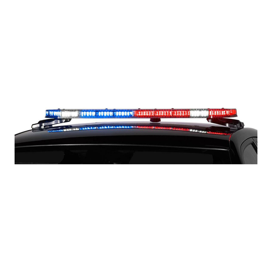
CHAPTER 2 An Overview of the Integrity Lightbar The INTEGRITY lightbar is a single-level LED lightbar with ROC (Reliable On-Board Circuitry) and Solaris LED technologies. ROC eliminates approximately 85 percent of potential failure points by ® incorporating a printed circuit board (PCB) in one assembly to substantially reduce the number of electrical connections. -
Page 12: Product Specifications
High output, long-life LEDs with no bulbs to change. Product Specifications Operating and technical specifications for the INTEGRITY lightbar are listed in this section by model. Dimensions Model INTEGRITY44 INTEGRITY51 Length 43.7 in (111.0 cm) 51.3 in (130.3 cm) Height 1.96 in (5.0 cm) -
Page 13: Chapter 3 Reprogramming The Lightbar
CHAPTER 3 Reprogramming the Lightbar HEAVY OBJECT—Use lifting aids and proper lifting techniques when removing or replacing this product. Failure to follow this warning may cause personal injury. Carefully unpack the lightbar assembly and any other products included in the shipment. Inspect them for damage that may have occurred during shipping. -
Page 14: Making The Electrical Connections For Reprogramming
Chapter 4: Wiring the INTEGRITY Lightbar in the Vehicle Making the Electrical Connections for Reprogramming To supply power to the lightbar, use a fully-charged 12-volt automotive battery and follow these steps: 1. Place the lightbar on a sturdy, flat surface. 2. -
Page 15: Switch Settings And Connectors On The Serial Interface Module
Chapter 3: Reprogramming the Lightbar Switch Settings and Connectors on the Serial Interface Module The switches to select flash patterns and lightbar functions are accessible throughon the PCB on the Serial Interface Module. Figure 3.2 shows the locations of the switches and connectors. See Table 3.1 for a desciption of switch settings and functions. -
Page 16: Table 3.2 Control Wires From The Serial Interface Module
Chapter 3: Reprogramming the Lightbar Selecting External SignalMaster Control To select External SignalMaster control: 1. Unplug the 24-pin harness from the Serial Interface Module. 2. Move Switch 4 on SW-2 to the up (OFF) position. 3. Plug the 24-pin harness into the Serial Interface Module. Selecting Internal SignalMaster Control (Factory Default) To select Internal SignalMaster control: 1. - Page 17 Chapter 3: Reprogramming the Lightbar Table 3.2 Control wires from the Serial Interface Module (continued) LOW POWER White/Black/ Dims the lights approximately 50 percent to prevent blinding approaching drivers. LOW POWER is only available in MODES 1 and 2 and is disabled when switched to another flash pattern, including MODE 3 and INTERSECTION.
- Page 18 Chapter 3: Reprogramming the Lightbar Mode 3 1. Apply 12 Vdc (+BAT) to the MODE 3 control wire (black/red) from the Serial Interface Module to display the assigned pattern. 2. On the Serial Interface Module, press and release the SW-1 pushbutton until the pattern you want appears on the lightbar.
-
Page 19: Table 3.3 Switch Settings For Intersection Operation
Chapter 3: Reprogramming the Lightbar • TAP II (push-on/push-off): the INTERSECTION flash pattern is turned on and off by pressing a momentary contact switch, such as a horn button. Momentary 12 Vdc turns on the pattern, a second momentary 12 Vdc signal turns it off. •... - Page 20 Chapter 3: Reprogramming the Lightbar Exiting Program Mode When you are finished, switch the Serial Interface Module from Operation Mode to Program Mode. 1. Unplug the 24-pin harness from the Serial Interface Module. 2. On the Serial Interface Module, move SW-2 Switch 6 to the up (OFF) position. 3.
-
Page 21: Chapter 4 Wiring The Integrity Lightbar In The Vehicle
CHAPTER 4 Wiring the INTEGRITY Lightbar in the Vehicle Before proceeding, ensure that the lightbar has been installed on the vehicle roof in accordance with the instructions included with the mounting kit. Depending on the type of vehicle and mounting system feature, there are two options available for installing the lightbar to the roof of the vehicle: hook-on mounting or permanent mounting. -
Page 22: Connecting Power To The Lightbar
Chapter 4: Wiring the INTEGRITY Lightbar in the Vehicle Separate all electronic equipment wiring from two-way radio equipment wiring. To avoid interference, keep two-way radio antennas a minimum of 18 in (45.7 cm) away from warning equipment. Whenever possible, run full wire lengths. DO NOT splice the wires. 10. -
Page 23: Installing The Serial Interface Module
Chapter 4: Wiring the INTEGRITY Lightbar in the Vehicle Figure 4.1 Power and cable connections DRIVER PASSENGER SIDE SIDE FUSE 40 A MAXI (+BAT) POWER LINE (RED) CAT5 COM. (NEG-) GROUND POWER LINE (BLACK) CABLE (GRAY) SERIAL INTERFACE – MODULE 12 Vdc VEHICLE J1 CONNECTOR... -
Page 24: Wiring The Serial Interface Module
Chapter 4: Wiring the INTEGRITY Lightbar in the Vehicle Install the three-foot-long, 24-conductor cable from the lightbar to the J1 input connector of the Serial Interface Module. NOTE: Powering multiple devices with a common control wire may cause one or more devices to briefly remain functional after signal power is removed. -
Page 25: Steady Burn
Chapter 4: Wiring the INTEGRITY Lightbar in the Vehicle Steady Burn Applying 12 Vdc (+BAT) to the red/white control wire turns on the red LED (driver side) and the blue LED (passenger side) Steady Burn modules. Steady Burn defaults to the HotFoot modules if red/blue colors are available;... -
Page 26: Scene Light, Left And Scene Light, Right
Chapter 4: Wiring the INTEGRITY Lightbar in the Vehicle Scene Light, Left and Scene Light, Right This function applies only to lightbars with SpectraLux Technology (INTEGRITY and Vision SLR). To use this function with the Serial Interface Module, place SW-2 Switch 3 in the Module in the down position (ON). -
Page 27: Figure 4.3 Signalmaster 331105 Controller (External Signalmaster Control)
Chapter 4: Wiring the INTEGRITY Lightbar in the Vehicle Internal SignalMaster (Factory Default) Internal operation uses the lightbar’s built-in SignalMaster controller to generate directional warning patterns. With internal operation, an external SignalMaster controller is not needed. A standard low- current switch box can activate the lightbar’s internal SignalMaster controller. To activate the lightbar’s internal SignalMaster controller, apply 12 Vdc (+BAT) to the SignalMaster control wires External SignalMaster External operation uses the Serial Interface Module to drive each SignalMaster directional warning head... -
Page 28: Figure 4.4 Smartsiren Ss2000Sm Series Controller (External Signalmaster Control)
Chapter 4: Wiring the INTEGRITY Lightbar in the Vehicle Figure 4.4 SmartSiren SS2000SM Series controller (external SignalMaster control) L I G S i g t e r NOTE: FOLLOW THE SS2000SM SERIES INSTALLATION S i g INSTRUCTIONS FOR OTHER WIRING. a r t t e r S i r... -
Page 29: Figure 4.5 Signalmaster Control Functions Wired To Ground For External Serial Interface Module Control
Chapter 4: Wiring the INTEGRITY Lightbar in the Vehicle Figure 4.5 SignalMaster control functions wired to ground for external Serial Interface Module control J1 CABLE TO POWER (+12 Vdc) SERIAL INTERFACE MODULE BLACK/RED MODE 3 MODE 2 BLUE/WHITE BLUE MODE 1 STEADY BURN RED/WHITE (or SCENE LIGHT, LEFT with SW-2 Switch 3... -
Page 30: Figure 4.6 Signalmaster Control Functions Wired To 12 Vdc For Internal Control
Chapter 4: Wiring the INTEGRITY Lightbar in the Vehicle Figure 4.6 SignalMaster control functions wired to 12 Vdc for Internal control J1 CABLE TO POWER (+12 Vdc) SERIAL INTERFACE MODULE BLACK/RED MODE 3 BLUE/WHITE MODE 2 BLUE MODE 1 RED/WHITE STEADY BURN (or SCENE LIGHT, LEFT with SW-2 Switch 3 down [ON] in the Serial Interface Module) -
Page 31: Figure 4.7 Typical Connections With A Signalmaster Controller (External Control)
Chapter 4: Wiring the INTEGRITY Lightbar in the Vehicle Figure 4.7 Typical connections with a SignalMaster controller (external control) Integrity Lightbar... -
Page 32: Figure 4.8 Typical Connections With A Model Sw400Ss Switch Module (Internal Control)
Chapter 4: Wiring the INTEGRITY Lightbar in the Vehicle Figure 4.8 Typical connections with a Model SW400SS Switch Module (internal control) Integrity Lightbar... -
Page 33: Figure 4.9 Typical Connections With A Smartsiren Model Ss2000Sm Controller
Chapter 4: Wiring the INTEGRITY Lightbar in the Vehicle Figure 4.9 Typical connections with a SmartSiren Model SS2000SM controller Integrity Lightbar... -
Page 34: Figure 4.10 Typical Connections With A Non-Signalmaster Controller
Chapter 4: Wiring the INTEGRITY Lightbar in the Vehicle Figure 4.10 Typical connections with a non-SignalMaster controller Integrity Lightbar... -
Page 35: Figure 4.11 Typical Connections With A Model Pa640 (Pa64000) Controller
Chapter 4: Wiring the INTEGRITY Lightbar in the Vehicle Figure 4.11 Typical connections with a Model PA640 (PA64000) controller Integrity Lightbar... -
Page 36: Chapter 5 Maintaining And Servicing The Integrity
CHAPTER 5 Maintaining and Servicing the INTEGRITY SHOCK HAZARD—Disconnect ALL power to the lightbar before any maintenance is performed. Failure to do so may result in property damage, serious injury, or death. BURN HAZARD—After prolonged operation, the unit gets hot and can cause burns. Do not touch the unit while or shortly after it has been operating. -
Page 37: Cleaning The Lightbar Lens
Chapter 5: Maintaining and Servicing the INTEGRITY Cleaning the Lightbar Lens CRAZING/CLEANING SOLUTIONS—The use of cleaning solutions, such as strong detergents, solvents, and petroleum products, can cause crazing (cracking) of the lightbar lens and reflectors. To clean the reflectors, use a soft, damp cloth. To clean the lens, use a soft cloth and a solution of water and a mild detergent. -
Page 38: Reinstalling The Lens
Chapter 5: Maintaining and Servicing the INTEGRITY Figure 5.2 Locations of the barrel nuts in lens (numbers indicate tightening sequence) FSC-66 FSC-67 290A7480 Reinstalling the Lens To reinstall the lens: 1. Reinstall the cover and lens. To prevent cross-threading the barrel nuts, back them counterclockwise until you hear the click of the threads engaging. -
Page 39: Removing A Pcb
Chapter 5: Maintaining and Servicing the INTEGRITY Removing a PCB To remove a PCB: 1. Disconnect all power to the lightbar. 2. Use a T27 Torx driver to remove the 1/4"-20 Torx-head barrel nuts securing the lens (Figure 5.2 on page 38). - Page 40 Chapter 5: Maintaining and Servicing the INTEGRITY Unplug the two ROC board connectors from the controller board (see diagram). Cycle power to the lightbar by removing both the Convergence Network CAT5 connector and the power connector and reconnecting both after at least 5 seconds. In response, the “ROC TX/RX” LED and the “Convergence TX/RX”...
-
Page 41: Troubleshooting The Lightbar
Chapter 5: Maintaining and Servicing the INTEGRITY Troubleshooting the Lightbar This section provides troubleshooting assistance for common problems. If you have any questions left unanswered, call the Federal Signal Service Department at 1-800-433-9132, 7 a.m. to 5 p.m., Monday through Friday (CT). Table 5.1 Troubleshooting tips Problem Corrective Action... - Page 42 Chapter 5: Maintaining and Servicing the INTEGRITY Table 5.1 Troubleshooting tips (continued) Problem Corrective Action The lightbar turns off when the Flash Ensure that the vehicle battery is fully charged. ✔ Takedown/Alley lights turn on Check that the lightbar’s red power line (+BAT) and black ✔...
-
Page 43: Getting Technical Support And Service
Chapter 5: Maintaining and Servicing the INTEGRITY Getting Technical Support and Service Federal Signal Corporation will service your equipment or provide technical assistance with any problems that cannot be handled locally. Any product returned to Federal Signal for service, inspection, or repair must be accompanied by a Return Material Authorization number. - Page 44 • Write the RMA number down, so that you can easily check on status of the returned equipment. Send all material with the issued RMA Number to: Federal Signal Corporation 2645 Federal Signal Drive University Park, IL 60484-3167 Attn: Service Department...
Need help?
Do you have a question about the INTEGRITY44 and is the answer not in the manual?
Questions and answers