Table of Contents
Advertisement
Quick Links
Advertisement
Table of Contents

Related Manuals for Tridonic EM powerLED ST FX


Summary of Contents for Tridonic EM powerLED ST FX
- Page 1 LED Driver EM powerLED ST FX Manual...
-
Page 2: Table Of Contents
Manual EM powerLED ST FX | 04-2020 | 1.3 | en Table of Contents Validity 4 Safety instructions 5 Intended use ....................... . . 5 Dangers associated with the operation of the system . - Page 3 Manual EM powerLED ST FX | 04-2020 | 1.3 | en Table of Contents Comparison of data sheet values with a 5-point guideline ..............44 Application of the 5-point guideline .
-
Page 4: Validity
The series comprises additional versions. However, the other versions EM powerLED PRO DIM FX 45W, EM powerLED BASIC FX 50W and EM powerLED BASIC FX 80W are not covered within this documentation. TRIDONIC GmbH & Co KG is constantly striving to improve all its products. This means that there may be changes in shape, features and technology. -
Page 5: Safety Instructions
The instructions in this section have been compiled to ensure that operators and users of combined emergency lighting LED Drivers of the EM powerLED ST FX 45W series from Tridonic are able to detect potential risks in good time and take the necessary preventative measures. -
Page 6: Additional Instructions
Manual EM powerLED ST FX | 04-2020 | 1.3 | en Safety instructions Additional instructions ½ CAUTION! Electromagnetic compatibility (EMC) Although the device meets the stringent requirements of the appropriate directives and standards on electromagnetic compatibility, it could potentially interfere with other devices under certain circumstances! -
Page 7: Introduction
Combining mains and emergency operation in one unit eliminates compatibility issues between LED Driver and emergency units and ensures an optimal electromagnetic compatibility. The EM powerLED ST FX devices are designed to meet the requirements of IEC 62034 (Automatic test systems for battery powered emergency escape lighting). -
Page 8: Portfolio Of Products
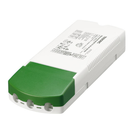
Manual EM powerLED ST FX | 04-2020 | 1.3 | en Portfolio of products Housing variants The EM powerLED ST FX is available in two different housing variants: compact and compact strain relief (independent). Image Description Housing variant compact Compact shape... -
Page 9: Output Voltage Range
Manual EM powerLED ST FX | 04-2020 | 1.3 | en Output voltage range Output voltage range The output voltage range results from the current selected. The diagram below shows the forward voltage ranges as a function of the output current and are intended as a guide. For detailed... -
Page 10: Functions In Mains Operation
Manual EM powerLED ST FX | 04-2020 | 1.3 | en Functions in mains operation Overview of the main functions in mains operation: Area Function Dimming switchDIM, p. 11 corridorFUNCTION V2, p. 15 Adjustable output current, p. 20 Adjustable via resistor or I-select 2 plug... -
Page 11: Switchdim
Manual EM powerLED ST FX | 04-2020 | 1.3 | en switchDIM switchDIM Description With the switchDIM function it is possible to use the mains voltage as a control signal. The phase is connected via a simple standard mains voltage push button to the terminal marked Rest/L and the neutral conductor is connected to the terminal Rest/N. - Page 12 Manual EM powerLED ST FX | 04-2020 | 1.3 | en switchDIM Procedure: Switch the device on/off by briefly actuating the switch (50-600 ms) or Dim the device by holding down the switch (> 600 ms) Synchronising devices If the devices in a system do not operate synchronously the devices must be synchronised, i.e. put in the same status (on/off) and the same dim level.
- Page 13 Manual EM powerLED ST FX | 04-2020 | 1.3 | en switchDIM Four-pole wiring Configuration: phase (L), neutral (N), control line (S/L), earth Benefits: No need for a control line thanks to connecting terminal 8 with the N-connection of the luminaire...
- Page 14 Manual EM powerLED ST FX | 04-2020 | 1.3 | en switchDIM ½ CAUTION! For five-pole wiring the neutral conductor must be connected to Rest/N. This prevents 400 V being applied between adjacent terminals if a different phase is used for the control input.
-
Page 15: Corridorfunction V2
Absence value: the luminous intensity when there is no person present (default: 10 %). Presence value: the luminous intensity when persons are present (default: 100 %). Adjusting the parameters With the series EM powerLED ST FX devices the parameters are fixed and cannot be changed. 15 / 63... - Page 16 Manual EM powerLED ST FX | 04-2020 | 1.3 | en corridorFUNCTION V2 Commissioning Activating the corridorFUNCTION Procedure by means of the mains voltage Activating the corridorFUNCTION is simple. If an a.c. voltage of 230 V is applied to the terminals Rest/N - Rest/L of the LED Driver for a period of at least 5 minutes the LED Driver detects the corridorFUNCTION and automatically activates it.
- Page 17 Manual EM powerLED ST FX | 04-2020 | 1.3 | en corridorFUNCTION V2 Procedure Connect mains voltage push button to the terminal marked Rest/L Connect neutral conductor to the terminal Rest/N Press the switch 5 times within 3 seconds Installation...
- Page 18 Manual EM powerLED ST FX | 04-2020 | 1.3 | en corridorFUNCTION V2 ½ CAUTION! Use conventional relay motion sensors! Electronic motion sensors (Triac) are not suitable because of their technical design. ½ CAUTION! Do not use glow switches! Glow switches may affect the control system.
-
Page 19: Dimming Technology
Manual EM powerLED ST FX | 04-2020 | 1.3 | en Dimming technology Dimming technology Output current/dimming level Time The dimming range is controlled by adjusting the amplitude of the current. The current value specified for the device corresponds to a dimming level of 100 %. -
Page 20: Adjustable Output Current
Adjustable output current Adjustable output current EM powerLED ST FX allow for different combinations of current and forward voltage based on the standard lumen packages available on the market. The output current can be adjusted via different resistance values, I-select 2 plugs. - Page 21 Please note that the resistor values for I-select 2 are not compatible with I-select (generation 1). Installation of an incorrect resistor may cause irreparable damage to the LED module(s). Resistors for the main output current values can be ordered from Tridonic. Further information about accessories can be found on the TRIDONIC homepage (see Reference list, p.
-
Page 22: Intelligent Temperature Guard
Manual EM powerLED ST FX | 04-2020 | 1.3 | en Intelligent Temperature Guard Intelligent Temperature Guard ½ WARNING! The maximum t temperature is the maximum permitted in terms of life time. Operating the LED Drivers above the permitted t temperature is not allowed. - Page 23 Manual EM powerLED ST FX | 04-2020 | 1.3 | en Intelligent Temperature Guard Min. power ca. 50 % dim level level Shut-off No shut off behaviour: behaviour Device will not shut off if temperature still rises. AC mode: Device switches to 15 % dimming level Automatic No automatic restart behaviour (because there is no shut off behaviour).
-
Page 24: Functions In Emergency Operation
Manual EM powerLED ST FX | 04-2020 | 1.3 | en Functions in emergency operation Overview of the main functions in emergency operation: Area Function Test function, p. 33 Automatic function and duration test Test activation via selftest Function test (interval) -
Page 25: Adjustable Output Current In Emergency Operation
Description If the EM powerLED ST FX switches to emergency operation in case of a power failure, the device will detect the forward voltage of the connected LED modules and set the correct LED current. Setting a constant output power ensures maximum light output in emergency mode for the specified operating time. - Page 26 Different battery cell numbers offer flexibility in the available emergency output power - 3 cells and 4 cells for LED modules from 20 V to 50 V forward voltage. The LED current in emergency mode is automatically adjusted by the EM powerLED ST FX based on the total forward voltage of the LED modules connected and the associated battery.
-
Page 27: Intelligent Multilevel Charging System
Shorter charge time after only a partial discharge. When the permanent power supply is switched on for the first time the EM powerLED ST FX starts to charge the batteries for 20 hours in fast charge mode. This 20-hour preparatory charge ensures that the new batteries are completely charged before being used. - Page 28 Manual EM powerLED ST FX | 04-2020 | 1.3 | en Rest mode and Relight function Rest mode can be used during short periods of time when a building is completely unoccupied and the mains supply is to be switched off intentionally, for example during a holiday period.
- Page 29 Manual EM powerLED ST FX | 04-2020 | 1.3 | en Rest mode and Relight function NOTICE Reapply the power supply does also deactivate Rest mode. In this case, the device switches from Rest mode to charge mode. Activate Inhibit mode...
- Page 30 Manual EM powerLED ST FX | 04-2020 | 1.3 | en Rest mode and Relight function Switching between operating modes The device has four different operating modes (Standby/Charge mode, Emergency mode, Rest mode and Inhibit mode). Depending on the initial mode and the length of the applied DC voltage pulse the device switches between these operating modes. The following...
-
Page 31: Indicator Led
Manual EM powerLED ST FX | 04-2020 | 1.3 | en Indicator LED Indicator LED System status is locally indicated by a bi-colour indicator LED. LED indication Status Description Permanent GREEN Standby, System OK Mains operation, battery is charged Fast flashing GREEN... - Page 32 Manual EM powerLED ST FX | 04-2020 | 1.3 | en Indicator LED Slow flashing RED Battery failure Battery failed duration test or function test -or- Battery is defect -or- Incorrect (1 s on - 1 s off) battery voltage...
-
Page 33: Settings For Emergency Tests
Manual EM powerLED ST FX | 04-2020 | 1.3 | en Settings for emergency tests Annotation: (1) First connection to the power supply (2) Phase, in which the power supply is switched on and off (possibly numerous times) (3) Phase, in which the power supply is "permanently" connected (no interruption for at least 5 days) -
Page 34: Test Times And Test Intervals
The commissioning test is often made more difficult because the power supply is switched on and off during the installation phase. This is the case, for example, if the site is powered off at night for security reasons. To address this problem, the EM powerLED ST FX monitors the power supply and will only start with the commissioning test if the power supply hasn't been interrupted for 5 days. -
Page 35: Weekly Function Test
NOTICE If the power supply is interrupted, the information in the EM powerLED ST FX is stored for at least one week. If the power supply is interrupted for more than one week, the EM powerLED ST FX will perform another commissioning test when the power supply returns (after 20 hours initial charge mode). -
Page 36: Annual Duration Test
36 NOTICE If the power supply is interrupted during battery replacement, the EM powerLED ST FX loses its memory contents. When the power supply returns, the EM powerLED ST FX will perform another commissioning test (after 20 hours initial charge mode) Adaptive test mode Adaptive test mode sets the time for the duration test to a time of minimum risk and minimum presence. - Page 37 Manual EM powerLED ST FX | 04-2020 | 1.3 | en Settings for emergency tests NOTICE The test switch can remain permanently connected and used as a startup tool. Starting the function test A short press on the button (0.15 - 1 s) starts a function test lasting 5 seconds.
-
Page 38: Determining Light Output In Emergency Operation
Manual EM powerLED ST FX | 04-2020 | 1.3 | en Determining light output in emergency operation To determine the light output in emergency operation the following parameters are crucial: LED forward voltage (total forward voltage of all connected LED modules) - Page 39 Manual EM powerLED ST FX | 04-2020 | 1.3 | en Parameter 1: LED forward voltage Example 1: 1 LED module DLE Given: Forward voltage DLE: 24.2 V (taken from data sheet) Wanted: Total forward voltage of all LED modules in emergency operation...
- Page 40 Manual EM powerLED ST FX | 04-2020 | 1.3 | en Parameter 1: LED forward voltage Example 2: 2 LED module DLE in parallel Given: Forward voltage DLE: 24.2 V (taken from data sheet) Wanted: Total forward voltage of all LED modules?
-
Page 41: Parameter 2: Led Current
Manual EM powerLED ST FX | 04-2020 | 1.3 | en Parameter 2: LED current Parameter 2: LED current Each EM powerLED ST FX has a specific current/voltage characteristic. The corresponding current/voltage curve can be found in the datasheet: EM powerLED ST FX 103 50V... - Page 42 Manual EM powerLED ST FX | 04-2020 | 1.3 | en Parameter 2: LED current Example 1: 1 LED module DLE Given: Total forward voltage of all LED modules: 24.2 V (calculated before) Wanted: LED current? Result: Figure: Determining LED current for EM converterLED ST FX 103 50V The two crossing points are at around 85 mA (minimum value) and 111 mA (maximum value).
-
Page 43: Parameter 3: Light Output In Emergency Operation
Manual EM powerLED ST FX | 04-2020 | 1.3 | en Parameter 3: Light output in emergency operation Parameter 3: Light output in emergency operation The ratio between emergency operation and normal operation is the same for light output and LED current. The values for normal operation can be found in the LED module data sheet, the value for the LED current in emergency operation can be found in the data sheet (see example above). -
Page 44: Compatibility Between Led Module And Led Driver
Manual EM powerLED ST FX | 04-2020 | 1.3 | en Compatibility between LED module and LED Driver There are two stages involved in the check for compatibility between the LED module and the LED Driver. The requirements for operating together can be checked by comparing the data sheets... - Page 45 Manual EM powerLED ST FX | 04-2020 | 1.3 | en Compatibility between LED module and LED Driver Comparison Value in LED Value in LED of… module Driver Detailed procedure Check whether voltage range of LED module is completely within the (2) Voltage Min.
-
Page 46: Application Of The 5-Point Guideline
Manual EM powerLED ST FX | 04-2020 | 1.3 | en Compatibility between LED module and LED Driver Application of the 5-point guideline The compatibility check with the 5-point guideline is shown here using two examples. Example 1 Comparison data for LED Driver... - Page 47 Manual EM powerLED ST FX | 04-2020 | 1.3 | en Compatibility between LED module and LED Driver Comparison data for LED module LED module Designation Fictitious LED module Manufacturer Other manufacturer Data sheet values of LED module Forward current 500 mA Max.
- Page 48 Manual EM powerLED ST FX | 04-2020 | 1.3 | en Compatibility between LED module and LED Driver Procedure Comparison of data sheet values Value in Value in LED Comparison of… module Driver Result Explanation To produce a luminous flux of 1,510 lm the LED module must be...
- Page 49 Manual EM powerLED ST FX | 04-2020 | 1.3 | en Compatibility between LED module and LED Driver Example 2 Comparison data for LED Driver LED Driver Designation LCI 20W 350mA-900mA TOP C Manufacturer TRIDONIC Data sheet values of LED Driver...
- Page 50 Manual EM powerLED ST FX | 04-2020 | 1.3 | en Compatibility between LED module and LED Driver Comparison data for LED module LED module Designation Fictitious LED module Manufacturer Other manufacturer Data sheet values of LED module Forward current 500 mA Max.
-
Page 51: Practical Tests
Manual EM powerLED ST FX | 04-2020 | 1.3 | en Compatibility between LED module and LED Driver Procedure Comparison of data sheet values Value in Value in LED Comparison of… module Driver Result Explanation To produce a luminous flux of 1,800 lm the LED module must be... -
Page 52: Installation Notes
Manual EM powerLED ST FX | 04-2020 | 1.3 | en Installation notes Technical aspects Transient behaviour Colour shift Connection during operation Parasitic capacitance Visual aspects Flickering Stroboscopic effect (video applications) Dimming behaviour Colour change/stability Luminous flux Conditions When conducting the tests the following conditions must be considered:... -
Page 53: Safety Information
Electronic control gear from Tridonic are protected for a maximum of 48 hour against overvoltage of up to 320 V. Make sure that the control gear is not exposed to overvoltage for long periods! Electronic control gear of the EM powerLED ST FX series from Tridonic have type of protection IP 20. -
Page 54: Function Of The Earth Terminal
Manual EM powerLED ST FX | 04-2020 | 1.3 | en Installation notes Function of the earth terminal The earth connection is conducted as protection earth (PE). The LED Driver can be earthed via earth terminal or metal housing (if device has metal housing). - Page 55 Manual EM powerLED ST FX | 04-2020 | 1.3 | en Installation notes Figure: Voltage peaks for LED Driver without earthing (left) and with earthing (right) NOTICE Irrespective of whether the LED Driver is earthed or not, LED modules must be insulated in accordance with the requirements of the luminaire protection class.
-
Page 56: Routing The Wires
Manual EM powerLED ST FX | 04-2020 | 1.3 | en Installation notes Routing the wires Tests NOTICE The performance of the prescribed tests and compliance with relevant standards are the responsibility of the luminaire manufacturer. The following descriptions merely indicate the most important tests and are no substitute for a full research of the relevant standards. - Page 57 Manual EM powerLED ST FX | 04-2020 | 1.3 | en Installation notes Wiring guidelines The cables should be run separately from the mains connections and mains cables to ensure good EMC conditions. The LED wiring should be kept as short as possible to ensure good EMC. The max. secondary cable length is 2 m (4 m circuit), this applies for LED output as well as for I-select and temperature sensor.
-
Page 58: Maximum Loading Of Circuit Breakers
The value is calculated through simulation programs based on the circuit breakers characteristic. Information about the maximum loading can be found in Tridonic data sheets. The following table shows the data for EM powerLED ST FX 45W as an example... - Page 59 Manual EM powerLED ST FX | 04-2020 | 1.3 | en Installation notes 1000 The combination of both parameters can also be displayed graphically. This results in the tripping characteristic for a certain circuit breaker. Current [A] Duration [µs] NOTICE...
- Page 60 Manual EM powerLED ST FX | 04-2020 | 1.3 | en Installation notes If several control gear are connected to one circuit breaker, the inrush current increases with the number of connected devices. Implementation of the simulation The above-mentioned parameters, height and duration of the current pulse in both the circuit breaker and the control gear, are entered into the simulation program.
- Page 61 Manual EM powerLED ST FX | 04-2020 | 1.3 | en Installation notes The different elements have the following meaning: Circuit breaker: B10, B13, B16, B20 (solid line) represent the tripping characteristics of different circuit breakers. Inrush current: The dotted lines represent different inrush currents.
- Page 62 Considering different system impedances Switch-on point used: should always be at max. input voltage Adopted cable lengths and cable data (Tridonic: Cable length 40 cm; Resistivity: 0.0172 Ohm * mm / m; inductance: 5nH / cm; terminal resistance: 2mOhm) The modeling of the control gear is performed from the input to the bus voltage electrolytic capacitor . For inductance the saturation values must be used.
-
Page 63: Reference List
Manual EM powerLED ST FX | 04-2020 | 1.3 | en Reference list Related documents Data sheet EM powerLED ST FX C 45 W: http://www.tridonic.com/com/en/download/data_sheets/EM_powerLED_ST_FX_C_45W_en.pdf Data sheet EM powerLED ST FX SR 45 W: http://www.tridonic.com/com/en/download/data_sheets/EM_powerLED_ST_FX_SR_45W_en.pdf Data sheet EM powerLED PRO DIM C 45 W: http://www.tridonic.com/com/en/download/data_sheets/EM_powerLED_PRO_DIM_C_45W_en.pdf...
Need help?
Do you have a question about the EM powerLED ST FX and is the answer not in the manual?
Questions and answers