Table of Contents
Advertisement
Advertisement
Table of Contents

Subscribe to Our Youtube Channel
Related Manuals for Johnson Controls York YKN2Open board


Summary of Contents for Johnson Controls York YKN2Open board
- Page 1 YKN2Open board Technical Information Ref.: N-27730_EN 1113...
-
Page 2: Table Of Contents
Index Index Components..........................1 Description of the components....................2 Buttons and LEDs........................3 Buttons and LEDs........................4 2.1.1 Test button..........................4 2.1.2 LEDs............................4 Configuration..........................5 Configuration..........................6 3.1.1 Microswitches...........................6 3.1.2 Accessories and Probes......................6 3.1.3 Communications with the thermostat..................7 Operation..........................8 General considerations......................9 Demand control unit.........................9 4.2.1 With DPC1 thermostat......................10 4.2.2 With external control.......................10 Switching of the main components..................10... - Page 3 Index Causes...........................19 5.2.1 Switching..........................19 5.2.2 Signalling..........................21 5.2.3 Reset............................23 Operating parameters......................24 Rooms............................25 Temperature tables........................27 Tables............................28 Communications........................32 YKN2Open board........................33 YKtool.............................38 YKtool N2 INT........................39 Specification history.......................40 10.1 History............................41...
-
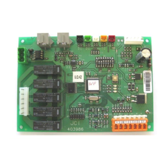
Page 4: Components
Components... -
Page 5: Description Of The Components
Components Description of the components 1.1 Description of the components The list of sensors and actuators of the unit is divided into several categories. The following components make up part of the unit assembly. • In cold only units they are responsible for generating cold. •... -
Page 6: Buttons And Leds
Buttons and LEDs... -
Page 7: Buttons And Leds
Buttons and LEDs Buttons and LEDs 2.1 Buttons and LEDs 2.1.1 Test button Situated on the main electronic board, it carries out different operations depending on how it is pressed: • If it is kept pressed until the yellow LED is activated, certain timings are shortened and any fault detected is reset. -
Page 8: Configuration
Configuration... -
Page 9: Configuration
Configuration Configuration 3.1 Configuration When the 24 V power supply is connected to the electronic board, the system configuration is verified. In order to do this, the following checks are carried out: 1. Microswitch reading. 2. Communication with the thermostat. 3. -
Page 10: Communications With The Thermostat
Configuration Configuration The outside probe can be fitted in the J6 of the board of the first compressor, or in the J3 of the economiser board. Whenever the economiser accessory is fitted, the system searches for the outside probe in the economiser as a first option. -
Page 11: Operation
Operation... -
Page 12: General Considerations
Operation General considerations The heat pump or cold unit is controlled using software located in the board. The operation of the system is determined by the position of the microswitches in the main board. The control algorithm also varies depending on the accessories that the board detects installed in the unit. -
Page 13: With Dpc1 Thermostat
Operation Switching of the main components • The electric resistors have less priority than the compressors (to generate heat) and they are arranged in order of operating hours. Those that have not activated the thermal switch protection activate to generate heat. •... -
Page 14: Outdoor Fan
Operation Switching of the main components • The indoor fan times 60 seconds when any stage stops and there is no demand (RESTIEVAC_CAL). N O T E This process removes residual heat or cold. • In the event of there being an air quality sensor, the indoor fan could activate if it demands air renewal Economiser, return fan and air quality detector, see on page 15 ). -
Page 15: Compressor
Operation Defrost • With the thermostat in OFF mode, the valve is deactivated independently of SW6. The 4-way valve only activates when its corresponding compressor is activated. – When the stage is deactivated, the compressor (V4VTICMP) is deactivated at the same time, as is also the 4-way valve 60 seconds later. -
Page 16: Switching
Operation Switching of the accessories 4.4.2 Switching When a defrost is started the following operations are carried out: 1. The 4-way valve is set to cool mode. 2. The outdoor fan is stopped. 3. The stage is inhibited. The demand control unit decides whether to start or not. 4. -
Page 17: Electrical Auxiliary Heat
Operation Switching of the accessories 4.5.3 Electrical auxiliary heat The program can control up to four electrical heating stages. The stages are started up in accordance with indications from the demand control unit. Whenever the electrical heating is in operation, the indoor fan will always be in operation. 4.5.4 Gas auxiliary heat The program can control up to four gas stages. -
Page 18: Economiser, Return Fan And Air Quality Detector
Operation Switching of the accessories There is a 15 °C minimum air supply temperature trip switch when this accessory is fitted. Hence, it is possible to avoid the discomfort that may be created when there is a very high percentage at low outdoor temperatures and the indoor fan is running continuously. -
Page 19: Energy Recovery System
Operation Switching of the accessories If the thermostat demands heat (winter cycle) and it is not possible to activate any heat stage, the damper will remain closed with the indoor fan stopped (if it is in automatic operating mode). In the event that it is in continuous mode, the indoor fan is operating. -
Page 20: Smoke And High Temperature Detector
Operation Switching of the accessories • If the thermostat is in HVAC mode (cool, heat or auto), there is no kind of demand and the air quality is correct, the unit is at a standstill. – If there is air quality demand: ♦... -
Page 21: Malfunctions
Malfunctions... -
Page 22: Malfunctions
Malfunctions Malfunctions 5.1 Malfunctions There are two different types of malfunction. Incidents do not cause the unit to stop and faults or lockouts cause the unit to stop. 5.2 Causes 5.2.1 Switching N O T E [See the operating parameters in the section Rooms, see on page 25]. Indoor fan thermal switch Activation of this causes the stoppage of the entire unit and a fault in the indoor fan thermal switch is signalled. - Page 23 Malfunctions Causes When the water temperature is below 3 °C (BACTPDFR_ON), an incident is signalled, and deleted when the condition disappears. If a short circuit or an open circuit is detected in one of the coil probes, and provided that there is no other stage: 1.
-
Page 24: Signalling
Malfunctions Causes Probes Opening or short circuit in the liquid probe, outdoor or indoor An incident is signalled in the corresponding probe if the value read is lower than ‑33.5 °C (NTCTPABIERTA), or higher than 93.5 °C (NTCTPCORTO). If this incident is produced in the liquid probe in heat mode, repeated defrosts are carried out with a maximum duration of 10 minutes or entry detection of the high-pressure switch signal. - Page 25 Malfunctions Causes In the event that more than one incident is produced, only the incident detected with the highest priority is signalled, provided that it has not yet been restored. Inasmuch as they are restored, the other existing incidents that have not yet been restored are displayed. Flashes Type Incident...
-
Page 26: Reset
Malfunctions Causes In the non-volatile memory the previous 9 faults to occur must be saved. Before saving the fault in the memory, a check is made to verify whether the previously saved fault is different to the present fault to be saved. -
Page 27: Operating Parameters
Operating parameters... -
Page 28: Rooms
Operating parameters Rooms 6.1 Rooms Parameter Description Value AVRNOREARMES Number of resets per thermostat OFF in one day BACPCPMP_OFF Opening for the water pump BACPCPMP_ON Opening to start the water pump BACTIH2O_MIN Time lapse for water minimum temperature 5 min. BACTIRTR Time to reattempt the condition check 20 min. - Page 29 Operating parameters Rooms Parameter Description Value ECOTPIMP_MIN Minimum supply temperature for economiser 11,5 °C ERTPCON Opening percentage to start up the air exhaust GASTION_OFF Gas stage delay 0 min. GOODINPUTCNT Number of identical readings to achieve the correct entry of DS2406 MAQTICMP_CMP Delay between start-ups of compressors 5 sec.
-
Page 30: Temperature Tables
Temperature tables... -
Page 31: Tables
Temperature tables Tables 7.1 Tables The following tables indicate the relationship between the temperature, resistance and voltage of the following probes: discharge, liquid, suction, outdoor, water, supply and return. J5 (Discharge) Temperature Heater Voltage Temperature Heater Voltage (°C) (Ohms) (°C) (Ohms) 328400 4,96973... - Page 32 Temperature tables Tables J5 (Discharge) Temperature Heater Voltage Temperature Heater Voltage (°C) (Ohms) (°C) (Ohms) 2582 2,81755 1,13302 2490 2,77283 1,10743 2402 2,72831 1,08304 2318 2,68411 1,05989 2237 2,63984 1,03646 2159 2,59558 1,01435 2085 2,55202 0,99198 2013 2,50810 0,96937 1944 2,46450 11 3 0,94814...
- Page 33 Temperature tables Tables J2 (Supply), J3 (Suction), J4 (Liquid), J6 (Outdoor), J13 (Water and return) Temperature Heater Voltage Temperature Heater Voltage (°C) (Ohms) (°C) (Ohms) 328400 4,83795 22952 3,38007 310260 4,82880 21865 3,32649 292120 4,81855 20836 3,27240 273980 4,80700 19860 3,21776 255840 4,79388...
- Page 34 Temperature tables Tables J2 (Supply), J3 (Suction), J4 (Liquid), J6 (Outdoor), J13 (Water and return) Temperature Heater Voltage Temperature Heater Voltage (°C) (Ohms) (°C) (Ohms) 2582 0,95052 0,25289 2490 0,92291 0,24592 2402 0,89613 0,23933 2318 0,87025 0,23314 2237 0,84498 0,22694 2159 0,82035 0,22113...
-
Page 35: Communications
Communications... -
Page 36: Ykn2Open Board
Communications YKN2Open board 8.1 YKN2Open board Based on the N2 Open protocol. The following table lists all the communication variables, which indicate: • The type of variable. • The ID number. • The description. • The range. • The units. N O T E Configure the network address. - Page 37 Communications YKN2Open board Value N2OpenType N2OpenId Description Range Description Units Suction Temperature 1 °C -50 min 160 max Suction temperature 1 Liquid Temperature 1 °C -50 min 160 max Liquid temperature 1 Outdoor Temperature °C -50 min 160 max Outdoor temperature Suction Temperature 2 °C -50 min 160 max...
- Page 38 Communications YKN2Open board Value N2OpenType N2OpenId Description Range Description Units High Pressure Sensor 2 Close / Open Input High-pressure sensor 2 fault input (input) Low Pressure Sensor 2 Close / Open Input Low-pressure sensor 2 fault input (input) High Pressure Sensor 3 Close / Open Input High-pressure sensor 3 fault input...
- Page 39 Communications YKN2Open board Value N2OpenType N2OpenId Description Range Description Units Gas Stage 2 OFF/ON Gas 2 ON output (out) Gas Stage 3 OFF/ON Gas 3 ON output (out) Gas Stage 4 OFF/ON Gas 4 ON output (out) Aux Stage 1 OFF/ON Resistor accessory 1 ON output (out)
- Page 40 Communications YKN2Open board Value N2OpenType N2OpenId Description Range Description Units Liquid Probe 2 Error OK / Fault Incident-Probe error Liquid probe 2 incident Discharge Probe 1 Error OK / Fault Incident-Probe error Discharge probe 1 incident Discharge Probe 2 Error OK / Fault Incident-Probe error Discharge probe 2 incident...
-
Page 41: Yktool
YKtool... -
Page 42: Yktool N2 Int
YKtool YKtool N2 INT 9.1 YKtool N2 INT The YKtool device is a portable diagnostics and testing system for air conditioning units based on the YKN2Open system, which consists of the display of the main system variables and the possibility of activating different stages in the various operating modes. -
Page 43: Specification History
Specification history... -
Page 44: History
Specification history History 10.1 10.1 History Version Description Release version...
Need help?
Do you have a question about the York YKN2Open board and is the answer not in the manual?
Questions and answers