Table of Contents
Advertisement
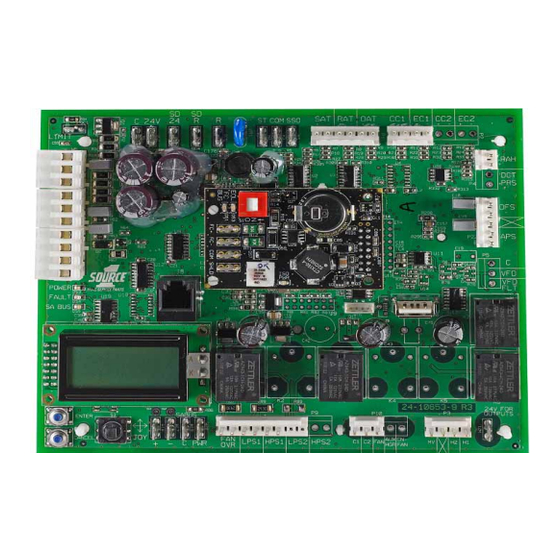
CCS Smart Equipment Control Board for Single Packaged
Unit (SPU) Controller
Installation Instructions
SE-SPU1011-1, SE-SPU1012-1
Applications
The new SE-SPU101x controllers replace the
RTU-100x controllers. All the RTU100x controllers are
discontinued, including the RTU-1003-0 VAV SPU
controller. The new SEC product offering provides new
controller options.
The SE-SPU101x-1 SEC Unit Control Board (UCB) is a
member of the Smart Equipment Controller (SEC)
product family. The controller is designed to run a pre-
engineered HVAC zoning application and provide the
inputs and outputs required for this application.
North American Emissions Compliance
United States
This equipment has been tested and found to
comply with the limits for a Class A digital device
pursuant to Part 15 of the FCC Rules. These limits
are designed to provide reasonable protection
against harmful interference when this equipment is
operated in a commercial environment. This
equipment generates, uses, and can radiate radio
frequency energy and, if not installed and used in
accordance with the instruction manual, may cause
harmful interference to radio communications.
Operation of this equipment in a residential area
may cause harmful interference, in which case the
users will be required to correct the interference at
their own expense.
Canada
This Class (A) digital apparatus meets all the
requirements of the Canadian Interference-Causing
Equipment Regulations.
Cet appareil numérique de la Classe (A) respecte
toutes les exigences du Règlement sur le matériel
brouilleur du Canada.
CCS Smart Equipment Control Board for Single Packaged Unit (SPU) Controller Installation
Installation
Special Tools Needed
•
wire strippers
•
small flat-head screwdriver
•
22 AWG (0.65 mm) 3-conductor, twisted, shielded
cable with a drain wire
Note: This drain wire is used only to group the
shielded cable. Do not use this drain wire as a
connection to the board.
•
wire nuts for 22 AWG drain wire
•
electrical tape
Mounting
The manufacturing facility mounts the controller. All of
the required power wiring, internal unit sensor wiring,
and output wiring is completed and tested at the
factory. The control application required for the specific
UCB is factory configured and ready for operation.
Wiring
Field Wiring Connections
In addition to power connections, the UCB requires a
Communication Bus connection. Address selection is
required for networking with a CCS Building
Automation System (BAS).
Power Wiring
The SEC UCB controller is factory wired for 24 VAC
power.
IMPORTANT: The 24 VAC power should not be
shared with other network devices. Sharing power to
other network devices may cause noise,
interference, and ground loop problems. You may
damage the controller by sharing power to other
devices.
Code No. LIT-12011479
Issued June 16, 2015
Instructions
1
Advertisement
Table of Contents

Related Manuals for Johnson Controls SE-SPU101 Series


Summary of Contents for Johnson Controls SE-SPU101 Series
- Page 1 CCS Smart Equipment Control Board for Single Packaged Unit (SPU) Controller Code No. LIT-12011479 Installation Instructions Issued June 16, 2015 SE-SPU1011-1, SE-SPU1012-1 Applications Installation The new SE-SPU101x controllers replace the Special Tools Needed RTU-100x controllers. All the RTU100x controllers are •...
- Page 2 In certain cases, you may need to share a 24 V Note: Be sure you observe polarity of each of the transformer with multiple CCS devices. Be sure that conductors in the communication cable. you maintain consistent +, -, and common wiring Communication Bus terminations on the shared CCS devices.
- Page 3 Control Board and Wiring Diagrams Figure 3 shows the location of the communication cable terminations on the SPU controller board. Figure 4 shows the VAV SPU controller communication riser. Com m unication Cable to Next VAV box* * M ove the 4-position term inal block from the Therm ostat inputs to the FC Bus connection of the com m unications card.
- Page 4 1 28 CO M CO M Zone Communication 1 28 CO M CO M Zone Communication – CCS Smart Equipment Control Board for Single Packaged Unit (SPU) Controller Installation Instructions...
- Page 5 End-of-Line (EOL) Terminations No EOL = No Signal Cushioning Daisy-chained RS485 protocol networks require (Bounce Back and Noise) end-of-line (EOL) termination to reduce interference. Interference is caused by signal reflection that occurs when data transmissions reach the end of a bus segment and bounce back (Figure 5).
- Page 6 Operation After the startup sequence finishes, the display shows XxXx on both lines if no alarm is active. The red Fault The controllers are supplied in a pre-configured format. LED stops flashing and turns off. The joystick, Enter, You do not need to configure the controller. Refer to the and Cancel buttons are operational.
- Page 7 If the Unit Control Board (UCB) fails to operate within the system bus is set to ON and all other its specifications, replace the unit. For a replacement system bus EOL switches are set to OFF. controller, contact the nearest Johnson Controls® representative. • Check connections, polarity, and lengths...
- Page 8 Metasys® and Johnson Controls® are registered trademarks of Johnson Controls, Inc. All other marks herein are the marks of their respective owners. © 2015 Johnson Controls, Inc. CCS Smart Equipment Control Board for Single Packaged Unit (SPU) Controller Installation Instructions Published in U.S.A.
Need help?
Do you have a question about the SE-SPU101 Series and is the answer not in the manual?
Questions and answers