Table of Contents
Advertisement
Quick Links
Advertisement
Table of Contents

Subscribe to Our Youtube Channel
Related Manuals for TOHATSU MFS 5D LPG


Summary of Contents for TOHATSU MFS 5D LPG
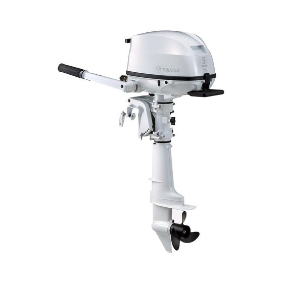
- Page 1 O W N E R’ S M A N U A L AAAA MFS 5D LPG OB No.003-11158-0BX...
- Page 2 MANUAL IN A SAFE LOCATION FOR FUTURE REFERENCE. Copyright © 2020 Tohatsu Corporation. All rights reserved. No part of this manual may be reproduced or transmitted in any from or by any means without the express written permission of Tohatsu Corporation.
- Page 3 ENOM00006-A To You, Our Customer Thank you for selecting a TOHATSU outboard motor. You are now the proud owner of an excellent outboard motor that will service you for many years to come. This manual should be read in its entirety and the inspection and maintenance proce- dures described later in this manual should be followed carefully.
- Page 4 ENOM00005-A Serial Number In the space below, please record the outboard motor's serial number (indicated both on the bracket and on the cylinder block). The serial number will be needed when ordering parts, and when making technical or warranty inquiries. Serial Number: ENOF01500-1 ENOF01501-0...
- Page 5 ENOM00007-0 NOTICE: DANGER/WARNING/CAUTION/Note Before installing, operating or otherwise handling your outboard motor, be sure to thor- oughly read and understand this Owner's Manual and carefully follow all of the instruc- tions. Of particular importance is information preceded by the words “DANGER,” “WARNING,”...
-
Page 7: Table Of Contents
CONTENTS 1. GENERAL SAFETY INFORMATION ........10 2. - Page 8 12. TOOL KIT AND SPARE PARTS ........65 13.
- Page 9 INDEX 1. GENERAL SAFETY INFORMATION 2. SPECIFICATIONS 3. PARTS NAME 4. LABEL LOCATIONS 5. INSTALLATION 6. PRE-OPERATING PREPARATIONS 7. ENGINE OPERATION 8. REMOVING AND CARRYING THE OUTBOARD MOTOR 9. ADJUSTMENT 10. INSPECTION AND MAINTENANCE 11. TROUBLESHOOTING 12. TOOL KIT AND SPARE PARTS 13.
-
Page 10: General Safety Information
GENERAL SAFETY INFORMATION ENOM00009-0 SAFE OPERATION OF BOAT As the operator/driver of the boat, you are responsible for the safety of those aboard and those in other boat around yours, and for following local boating regulations. You should be thoroughly knowledgeable on how to correctly operate the boat, outboard motor, and accessories. - Page 11 GENERAL SAFETY INFORMATION ENOM00010-0 SERVICING, REPLACEMENT PARTS & LUBRICANTS We recommend that only an authorized service shop perform service or maintenance on this outboard motor. Be sure to use genuine parts, genuine lubricants, or recom- mended lubricants. ENOM00011-B MAINTENANCE As the owner of this outboard motor, you should be acquainted with correct mainte- nance procedures following maintenance section of this manual (See page 44).
-
Page 12: Specifications
SPECIFICATIONS ENOM00810-D MODEL FEATURE F5D LPG Model F5D LPG F5D LPG SP*2 Type Transom heights Tiller Handle Remote Control *1 Manual tilt *1: Option *2: SP model equip with charging coil as a standard. ENOM00811-D MODEL NAME EXAMPLE F 5 DLPGL Model Horse Product... - Page 13 Hand Vibration Level (ICOMIA 38/94) m/sec2 *1 With propeller, with battery cable. *2:Equipped only for SP model, the other models OPTION. Remark: Specifications subject to change without notice. Tohatsu outboard is power rated in accordance with ISO8665 (propeller shaft output).
-
Page 14: Parts Name
PARTS NAME ENOM00402-A ENOF01502-B1 Tilt Handle Thrust Rod Engine Oil Drain Screw Top Cowl Clamp Bracket Shut Off Valve Bottom Cowl Clamp Screw Regulator Cooling Water Check Port Throttle Grip Mixer Tilt Lever Shift Lever Steering Adjustment Screw Starter Handle Anode Choke Knob Anti Ventilation Plate... -
Page 15: Label Locations
LABEL LOCATIONS ENOM00019-A Warning label locations 1, 2, 3, 4 ENOF01503-B1... - Page 16 LABEL LOCATIONS Warning regarding urge to read the 5-1. Warning regarding high temperature. owner's manual. 5-2. Warning regarding rotating object. 5-3. Warning regarding high voltage 3WE-72180-000 Warning regarding oil pressure (See page 26). ENOF00131-0 Warning regarding stop switch (See page 34) ENOF00005-S1 ENOF00131-B Warning regarding high temperature.
- Page 17 5 THIS ENGINE IS CERTIFIED TO OPERATE ON PROPANE. EPA Emissions Regulations The Emission Control Information label Outboards sold by Tohatsu America Cor- was affixed to engines as permanent evi- poration in the United States are certi- dence of EPA certification.
-
Page 18: Installation
INSTALLATION Keep the outboard motor in a vertical ENOM00024-B 1. Mounting the outboard position when mounting. motor on boat ENOW00006-0 WARNING Most boats are rated and certified in terms of their maximum allowable horsepower, as shown on the boat’s certification plate. Do not equip your boat with an outboard motor that exceeds this limit. -
Page 19: Remote Control Device Installation (Option)
INSTALLATION ENON00930-0 Note Do not use tools to tighten clamp screws. Over tightening could result in damage to the clamp screws and clamp brackets. 5−25 mm ENON00002-0 (0.2−1 in) Note A rope is not included in the standard ENOF01506-0 accessories. 1. -
Page 20: Battery Installation (For Sp Model)
INSTALLATION ENOM00860-0 ENOM00029-A Remote control cable length 3. Battery installation (For SP ENOW00100-A model) CAUTION ENOW00012-0 Be careful not to loop the remote control cables to a diameter of 406 mm (16 inches) WARNING or less. Otherwise, it affects the service life of the cable. -
Page 21: Altitude Adjustment Kit Installation
1. Connect the battery cable to the mance. Contact authorized Tohatsu leads that come from the bottom dealer for more detail. cowl. 2. Place the battery box in a convenient position away from possible water spray. -
Page 22: Pre-Operating Preparations
ENOM00031-B FUEL RATING the engine. Leaking LP gas may cause a fire or explo- TOHATSU engines will operate satisfacto- sion if ignited causing serious bodily injury rily when using a major brand of propane or death. gas meeting the following specifications: Turn off the engine when handling LP gas Propane fuel only. -
Page 23: Engine Oil Filling
PRE-OPERATING PREPARATIONS Do not use a LPG tank expired life span. Re qualification will be required after specific years from the date of manufac- ture. Please follow to the LPG tank manu- factures' instruction. When filling fuel, keep LPG tank in an upright position. - Page 24 PRE-OPERATING PREPARATIONS Engine oil volume Approximately 450 mL (0.48 US qt.) ENOW0002A-A CAUTION Use of engine oils that do not meet these requirements will result in reduced engine life, and other engine problems.
-
Page 25: Break-In
PRE-OPERATING PREPARATIONS ENOM00033-A 4. Break-In Your new outboard motor and lower unit Always attempt to stay on the windward side of emission. require break-in for the moving compo- nents a ccording to the conditions described in the following time table. ENOW00023-1 Please refer to ENGINE OPERATION sec- CAUTION... -
Page 26: Warning System
PRE-OPERATING PREPARATIONS ENOM00039-A 5. Warning system If outboard motor encounters an abnor- mal condition of fault, the warning lamp (LED) will be ON. See next page for conditions which will lead to an abnormal condition or fault. ENOM00040-D Location of warning lamp Warning lamp (LED) Tiller handle models: Located on the bot- tom cowl. - Page 27 PRE-OPERATING PREPARATIONS ENOM00041-E Warning indicators, faults and remedy Warning indicators Description of faults Remedy Lamp (LED) On for several Normal system test when start up sec. Engine speed exceeds maximum allowable RPM Low oil pressure Remarks *1: In this case, oil pressure switch is “ON”. High speed ESG (Electronic Safety Governor) High speed ESG is a device to prevent over revolution of the engine.
-
Page 28: Engine Operation
ENGINE OPERATION ENOM00042-0 ENOM00044-E Before starting 1. Fuel feeding ENOM00246-0 ENOW00951-0 Oil Level checking WARNING Check the engine oil level before each use. If the oil level is low or too high, the Check the special gas hose connector and connection points on the engine to make life of the engine will be shortened signif- sure that they are not contaminated with... -
Page 29: Starting The Engine
ENGINE OPERATION 2. Connect the hose to the LPG tank by ENOM00045-C 2. Starting the engine turning connector counter clock- wise. ENOW00958-0 WARNING Do not remove or install the top cowl after the engine has been started. The exposed rotating engine parts or moving parts cause serious injury. - Page 30 ENGINE OPERATION 2. Set the shift lever in the Neutral posi- ENOW00036-0 tion. CAUTION Be sure to stop engine immediately if cooling water check port is not discharging water, and check if cooling water intake is blocked. Operating engine could lead to overheating potentially leading to engine damage.
- Page 31 ENGINE OPERATION 5. Pull the starter handle slowly until you ENOM00042-A Emergency starting feel engagement, keep pulling till you ENOW00099-A feel less resistance. Then pull it WARNING quickly. repeat if necessar y until started. When the emergency starter rope is used for starting engine;...
-
Page 32: Warming Up The Engine
ENGINE OPERATION 2. Disconnect the rink of the starter ENOW00860-0 lock rod. CAUTION Be sure to keep the harness away from the rotation parts. 6. Be sure to install the stop switch lock to the stop switch, and attach the stop switch lanyard securely to the operator or to the operator's PFD (Personal Flotation Device.) -
Page 33: Forward, Reverse, And Acceleration
ENGINE OPERATION below 5°C (41°F) ENOW00038-A This allows the lubricating oil to circulate WARNING to all parts of the engine. Operating the Attach other end of emergency stop engine without warm up shortens the switch lanyard to the operator's PFD (Per- engine's life. -
Page 34: Stopping The Engine
ENGINE OPERATION ENOW00863-0 Forward CAUTION 1. Turn the throttle grip to reduce Idle speed may be higher during warming up engine speed. of engine. If shifted to Forward or Reverse 2. When the engine reaches trolling (or during warming up, it may be difficult to shift idling) speed, quickly pull the shift back to neutral. - Page 35 ENGINE OPERATION crew(s) and or objects on the boat to be ENOW00869-B thrown forward due to inertial force. WARNING Tiller handle type After stopping the engine: 1. Turn the throttle grip to the slow After close the valve of the tank, consume position.
-
Page 36: Steering
ENGINE OPERATION when adjusting trim angle to prevent injury in case the outboard motor body falls. Unsuitable trim position can cause loss of control of boat. When testing a trim posi- tion, run boat slow initially to see if it can ENOF00891-0 be controlled safely. -
Page 37: Tilt Up And Down
ENGINE OPERATION 1. Stop the engine. ENOM00053-A Improper trim angle (bow rises too 2. Shift into neutral position. high) Set the thrust rod (or preset knob) lower 3. Tilt up the outboard motor. if the bow of the boat rises above hori- 4. -
Page 38: Shallow Water Operation
ENGINE OPERATION ENOW00056-A WARNING When tilting up outboard motor with fuel joint for over a few minutes, be sure to dis- connect fuel hose, or fuel may leak, poten- tially catching fire. ENOW00057-0 CAUTION Do not tilt up outboard motor while engine running, or no cooling water may be fed, leading to engine seizure due to overheating. - Page 39 ENGINE OPERATION bracket and the clamp bracket. Be sure to tilt the outboard motor down slowly. ENOW00053-0 CAUTION While in shallow water drive position, do not operate the outboard motor in Reverse. Operate the outboard motor at slow speed and keep the cooling water intake sub- merged.
-
Page 40: Removing And Carrying The Outboard Motor
REMOVING AND CARRYING THE OUTBOARD MOTOR ENOM00070-D 1. Removing the outboard motor ENOW00064-0 CAUTION Engine may be hot immediately after operat- ing and could cause burns if touched. Allow engine to cool down before attempting to carry the outboard. ENOF01505-1 ENOM00071-A 2. -
Page 41: Trailering
REMOVING AND CARRYING THE OUTBOARD MOTOR ENOF01510-1 Keep the outboard motor in a vertical position when carrying. ENOF01532-0 The optional outboard motor stand is recommended for keeping the outboard motor vertical both during transport and storage. ENOF01533-0 ENON00941-0 Note When laying the outboard front-side down, turn the clamp bracket 90°... - Page 42 REMOVING AND CARRYING THE OUTBOARD MOTOR (like a transom saver bar) in the tilted posi- ENOW00073-A tion. WARNING When transporting a boat on a trailer Be sure to disconnect fuel connector except with the outboard motor still attached, when operating engine. disconnect the fuel line from the out- Fuel leakage is a fire or explosion hazard, which can cause serious injury or death.
-
Page 43: Adjustment
ADJUSTMENT ENOM00073-0 EENOM00074-A 1. Steering friction 2. Throttle grip friction Tiller handle type ENOW00074-B WARNING ENOW00074-E WARNING Do not overtighten the throttle adjustment screw or it could result in difficulty of move- Do not over tighten the steering friction ment resulting in the loss of control causing adjustment screw it could result in difficulty an accident and could lead to severe injury. -
Page 44: Inspection And Maintenance
INSPECTION AND MAINTENANCE ENOM00077-0 Care of your outboard motor To keep your outboard motor in the best operating condition, it is very important that you perform daily and periodic maintenance as suggested in the mainte- nance schedules that follow. ENOW00077-0 CAUTION Your personal safety and that of your pas- sengers depends on how well you main-... -
Page 45: Daily Inspection
INSPECTION AND MAINTENANCE ENOM00428-0 1. Daily Inspection Perform the following checks before and ENOW00078-1 after use. WARNING Do not use outboard motor if any abnormal- ity is found during pre-operation check oth- erwise it could result in severe damage to the motor or severe personal injury. - Page 46 INSPECTION AND MAINTENANCE ENOM00081-B ENON00025-0 Oil level checking Note 1. Place the engine in a vertical posi- Consult with an authorized dealer if the tion. engine oil is milky color, or appears con- taminated. 2. Remove the top cowl and the oil filler cap (dipstick).
- Page 47 INSPECTION AND MAINTENANCE ENOM00083-1 ENOM00085-A Washing outboard motor Flushing attachment ENOW00922-0 ENOW00081-0 CAUTION WARNING To prevent the engine from starting when Do not start engine without removing pro- you are near the propeller, remove the stop peller, or accidentally turning propeller switch lock.
- Page 48 If the fuse continues to blow, request an age, be sure the water level is at least 10 cm (4 in.) above the anti ventilation plate. authorized Tohatsu dealer to inspect the And be sure to remove the propeller, when outboard motor.
- Page 49 INSPECTION AND MAINTENANCE 4. Remove the fuse and check it. If the fuse is blown, replace it with a fuse of the same specified rating. The out- board motor is supplied with spare fuses in the spare fuse holder. ENOF01524-0 1.
-
Page 50: Periodic Inspection
INSPECTION AND MAINTENANCE ENOM00431-0 2. Periodic Inspection It is important to inspect and maintain your outboard motor regularly. At each interval on the chart below, be sure to perform the indicated servicing. Maintenance intervals should be determined according to the number of hours or number of months, which- ever comes first. - Page 51 INSPECTION AND MAINTENANCE Inspection intervals Every Every Every Every First 20 Description Inspection procedure Remarks hours hours hours hours hours of 1 of 3 of 6 of 1 of 2 month months months year year Throttle cable Check and replace if necessary Shift/ Throttle Shift link...
- Page 52 INSPECTION AND MAINTENANCE 2. Turn the steering on the outboard motor left. 3. Put a oil drain pan under the oil drain screw. 4. Remove the oil drain screw and com- pletely drain oil from the engine. ENOF01531-0 1. Upper limit 2.
- Page 53 INSPECTION AND MAINTENANCE ENOM00122-0 LPG tank, gas hose and connector inspection ENOW00953-0 WARNING Be sure to select LPG tank, gas hose and conne c tor in accordance with re com- mended specification. ENOW00954-0 WARNING Do not use a LPG tank expired life span. ENOF01514-0 Re qualification will be required after 3.
- Page 54 INSPECTION AND MAINTENANCE accidentally start leading to serious per- ENOW00095-0 sonal injury. Disconnect battery cable if CAUTION possible. The propeller edge is thin and sharp. Wear Do not reuse oil plug gasket. Always use new the groves during replacement to protect gasket and tighten oil plug properly to pre- your hands.
- Page 55 INSPECTION AND MAINTENANCE 4. Apply water proof grease to the pro- ENOM00087-A Spark plugs replacement peller shaft before installing a new ENOW00087-0 propeller. WARNING 5. Install the thrust holder, propeller, stopper, washer and propeller nut Do not reuse spark plug with damaged insulation, or sparks can leak through onto the shaft.
- Page 56 INSPECTION AND MAINTENANCE 6. Measure the spark plug electrode gap with a wire type feeler gauge. The gap should be 0.8-0.9 mm (0.031-0.035 inches). If the gap is different, replace the spark plug with a new one Use spark plug NGK DCPR-6E. ENOF00085-0 1.
- Page 57 INSPECTION AND MAINTENANCE ENOM00088-B Anode replacement A sacrificial anode protects the outboard motor from electrolytic corrosion. Anode is located on the gear case, etc.. When the anode is eroded more than 1/3 of original size, replace it. ENON00029-0 Notes Never grease or paint the anode. At each inspection re-tighten the anode attaching bolt.
- Page 58 INSPECTION AND MAINTENANCE ENOM00960-0 Grease point Apply water proof grease to the parts shown below. ENOF01519-1...
-
Page 59: Off-Season Storage
INSPECTION AND MAINTENANCE ENOM00100-A 5. Pull the recoil starter several turns to 3. Off-season storage lubricate inside the cylinder. ENOW00930-0 ENOW00955-0 WARNING WARNING Be sure to remove stop switch lock to Close the valve of the LPG tank. prevent ignited the spark plugs. After close the valve of the tank, consume Put a cloth to spark plug hole and wipe up remained fuel by running the engine if the... -
Page 60: Pre-Season Check
INSPECTION AND MAINTENANCE anti-clockwise so that it does not interfere with the ground. Then tighten up the steer- ing adjustment screw to maintain its posi- tion (see page 43). ENOM00102-0 Battery ENOW00931-A WARNING ENOF01510-1 Place the battery away from any source of ENOM00442-0 fire, sparks and open flames such as If the outboard motor must be laid down,... -
Page 61: Submerged Outboard Motor
INSPECTION AND MAINTENANCE The following are the emergency mea- Specific Grav- Terminal Volt- Charge Condi- sures to be taken for a submerged out- ity at 20° age (V) tion board motor, if you can not take it your 1.120 10.5 Fully discharged dealer right away. -
Page 62: Striking Underwater Object
INSPECTION AND MAINTENANCE 2. The amount of gas ejected from LPG ENOM00120-2 8. Auxiliary outboard motor tank differs in accordance with the operation outdoor temperature, so consult with your LPG dealer with regard to meth- ods of increasing tank capacity and When the auxiliary outboard motor is not other measures if necessary. -
Page 63: Troubleshooting
TROUBLESHOOTING TROUBLESHOOTING ENOM00436-0 If you encounter a problem, consult the check list below to determine the cause and to take the proper action. An authorized dealer will always be happy to provide any assistance and information. Possible cause Empty fuel tank Incorrect connection of fuel system Air entering fuel line Deformed or damaged fuel hose... - Page 64 TROUBLESHOOTING Possible cause Incorrect valve clearance Poor sealing of cylinder head Poor sealing of intake or exhaust valve seat Wear of piston, piston ring and cylinder Carbon deposits in the combustion chamber Poor tightening of spark plug Insufficient cooling water flow, clogged or defective pump Faulty thermostat Damage of anti-ventilation plate...
- Page 65 TOOL KIT AND SPARE PARTS ENOM00437-0 Items Quantity Remark Tool bag Pliers Socket wrench 10 × 13 mm Service tools Socket wrench 16 mm Socket wrench handle Screwdrivers Cross-and straight-point Screwdriver handle Emergency starter rope Spark plug NGK: DCPR6E Spare parts Split pin Stop switch lock...
- Page 66 PROPELLER TABLE ENOM00438-0 Use a genuine propeller. A propeller must be selected so that the engine RPM measured at wide open throttle while cruising is within the recommended range. 5: 5000–6000 min (rpm) Standard propeller on Propeller Size (Diameter × pitch) Propeller the model Mark...
- Page 67 EMISSION CONTROL SYSTEM INFORMATION ENOM01000-0 ENOM01003-0 Emission Sources Clean Air Acts of the United States and California, and Environment Canada Carbon monoxide, oxides of nitrogen and EPA, California, and Canadian regulations hy drocarbons are produce d in the require all manufacturers to provide writ- course of the combustion process.
- Page 68 Star label The emission control system in your This outboard motor is labeled with the Tohatsu out board motor has be en California Air Resources Board (CARB) designed, built, and certified to conform star label. A description of this label is with the EPA and California emission reg- presented below.
- Page 69 EMISSION CONTROL SYSTEM INFORMATION ENOF01003-0 ENOF01001-0 ENOM01009-0 ENOM01011-0 One Star-Low Emission Three Stars-Ultra Low Emission One Star- Low emission The one-star The three-star label identifies engines label identifies engines that meet the Air that meet the Air Resources Board’s Per- Resources Board’s Personal Watercraft sonal and Ou t board marine engine 2001...
- Page 70 O W N E R’ S M A N U A L MFS 5D LPG 5-4, Azusawa 3-Chome, Itabashi-Ku Tokyo 174-0051, Japan Tel: +81-3-3966-3117 Fax: +81-3-3966-0090 www.tohatsu.com...
Need help?
Do you have a question about the MFS 5D LPG and is the answer not in the manual?
Questions and answers