Table of Contents
Advertisement
Quick Links
Advertisement
Table of Contents

Related Manuals for Hioki 3447-01


Summary of Contents for Hioki 3447-01
- Page 1 INSTRUCTION MANUAL 3447-01 TEMPERATURE HiTESTER...
-
Page 3: Table Of Contents
Before Measurement ......23 3.1.1 Switching the 3447-01 ON or OFF ..23 3.1.2 Auto Power Save Function ....24 3.1.3 Date and time settings (on the 3447-01) .. 26 3.1.4 Date and Time Settings (Using a Computer) ......27... - Page 4 3.5.2 Confirming Comparator Value Settings .43 Key Lock Function .........44 Buzzer Function ........45 Print Function ........46 Data Communication with a Computer ..48 Chapter 4 Specifications 3447-01 TEMPERATURE HiTESTER ..49 9478 SHEATH TYPE TEMPERATURE PROBE ..........53 9479 SHEATH TYPE TEMPERATURE PROBE ..........54...
- Page 5 Chapter 5 Maintenace and Service Replacing the Batteries ......55 Disposing the Lithium Battery .... 55 Cleaning ..........57 Service ..........57...
-
Page 7: Introduction
Using the product in such conditions could cause an electric shock, so contact your dealer or Hioki rep- resentative for repair. • Before using the product the first time, verify that it operates normally to ensure that the no damage occurred during storage or shipping. -
Page 8: Safety Notes
Safety Notes This product is designed to conform to IEC 61010 Safety Standards, and has been thor- oughly tested for safety prior to shipment. However, mishandling during use could result in injury or death, as well as damage to the product. Be certain that you understand the instructions and precautions in the man- ual before use. - Page 9 The following symbols in this manual indicate the relative importance of cautions and warnings. Indicates that incorrect operation presents an ex- treme hazard that could result in serious injury or death to the user. Indicates that incorrect operation presents a sig- nificant hazard that could result in serious injury or death to the user.
- Page 10 Measurement categories (Overvoltage categories) This product conforms to the safety requirements for CAT I measurement products. To ensure safe operation of measurement prod- ucts, IEC 61010 establishes safety standards for various electrical environments, categorized as CAT I to CAT IV, and called measurement catego- ries.
-
Page 11: Usage Notes
Usage Notes Follow these precautions to ensure safe operation and to obtain the full benefits of the various func- tions. Do not attempt to measure the temperature of objects carrying a voltage. Doing so will result in a short-circuit accident or an electro- cution accident. - Page 12 • The sheath of the temperature probe is filled with magnesium oxide powder. If the probe is broken, the magnesium oxide powder may spill out. Be careful not to subject the sheath to excess stress. Inhaling large quantities of mag- nesium oxide may be hazardous to your health.
-
Page 13: Chapter 1 Overview
1.1 Product Overview Chapter 1 Overview 1.1 Product Overview The 3447-01 TEMPERATURE HiTESTER is a water-resistant thermometer designed for use with the platinum resistance thermometer sonsor (Pt100). By using the product in combination with the spe- cial 9478 SHEATH TYPE... -
Page 14: Parts Names And Functions
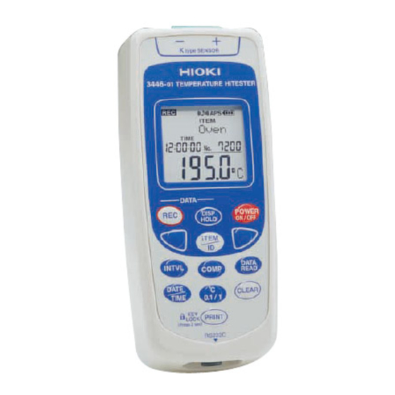
1.2 Parts Names and Functions 1.2 Parts Names and Functions 1.2.1 3447-01 TEMPERATURE HiTESTER 3447-01 TEMPERATURE HiTESTER Strap band Sensor connector attachment hole LCD display (Protective cap) Buttons Battery compartment RS-232C connector (Protective cap) Strap band attachment hole... - Page 15 1.2 Parts Names and Functions LCD display Displays temperature readings and set- tings. Sensor connector Connect either the 9478 or 9479 SHEATH TYPE TEMPERATURE PROBE. Protective cap Place on unused connectors. Strap band For attaching the provided strap band. attachment hole Battery The product uses 4 LR03 (AAA) alkaline compartment...
- Page 16 Records temperature and time readings. Interval Recording Mode Starts and stops interval recording. Activates the display hold function. Turns the 3447-01’s power on/off. (Press for 2 seconds) • Selects Item or ID type. • Selects a data number for reading.
- Page 17 1.2 Parts Names and Functions Sets the recording interval for interval record- ing. When this is off, manual recording is selected. Displays comparator value settings. Displays recorded data. Toggles the display between date and time. Sets date and time. (Press for 2 seconds) Toggles temperature display between Sensor 1 and sensor 2.
- Page 18 Indicates that the item (product name) is being displayed. Indicates that the ID (worker name) is being displayed. INTVL Indicates that the 3447-01 is in interval recording mode or in recording interval setting mode. Recording interval Displays the recording interval.
- Page 19 1.2 Parts Names and Functions TIME Indicates time display. Date and time Displays the date or time. display COMP Hi IN Lo Indicates comparator settings mode, or comparator test results. Data number Displays a number for a data item. display Sensor number Indicates the number for the connected sensor.
-
Page 20: 9478 Sheath Type Temperature Probe
Grip 1.2.3 9479 SHEATH TYPE TEMPERATURE PROBE With the 3447-01 you can record temperatures in the same manner using the button on the tempera- ture probe’s grip, or the button on the 3447-01 itself. Measuring point Sensor connector Grip Recording... -
Page 21: Chapter 2 Installation
2.1 Attaching the strap band Chapter 2 Installation 2.1 Attaching the strap band You can attach the strap band provided with the product. There are holes on the top and bottom of the product. Attach the strap handle to these holes as necessary. -
Page 22: Mounting Or Replacing The Batteries
2.2 Mounting or Replacing the Batteries 2.2 Mounting or Replacing the Batteries • Do not mix old and new batteries, or differ- ent types of batteries. Also, be careful to observe battery polarity during installation. Otherwise, poor performance or damage from battery leakage could result. - Page 23 2.2 Mounting or Replacing the Batteries New batteries should last for about 15 days of con- tinuous use, with the auto power save function switched off. Batteries should last for about 1 month or more of continuous recording using the product in interval recording mode (with the recording interval set to 1 minute or longer), and with the auto power save function switched on.
-
Page 24: Connecting The Temperature Probe
2.3 Connecting the Temperature Probe 2.3 Connecting the Temperature Probe • To avoid damage to the product, protect it from vibration or shock during transport and handling, and be especially careful to avoid dropping. • To avoid damaging the product, never connect any sensor other than the 9478 or 9479 SHEATH TYPE TEMPERATURE PROBE (with recording switch) to the sensor connector. - Page 25 2.3 Connecting the Temperature Probe • The sensor used in the temperature probe is a precision platinum element. Please note that excessive voltage pulses or static discharges can destroy the element.To avoid damage or malfunction, avoid hitting the tip of the tempera- ture probe and overly bending the leads.
- Page 26 2.3 Connecting the Temperature Probe Connecting the temperature probe oupling To lock the connector, grip the connector and turn the arrow upwards until you hear a click. Hold the connector (not by the coupling) and lightly pull it to confirm that it is prop- erly connected.
-
Page 27: Connecting The Rs-232C Cable
2.4 Connecting the RS-232C Cable 2.4 Connecting the RS-232C Cable Using the optional 9674 RS-232C PACKAGE, you can connect the product to a computer or a printer for exchange of data. • To avoid damaging the product, never connect any cable other than the supplied cable to the RS-232C connector. - Page 28 2.4 Connecting the RS-232C Cable Connecting the RS-232C cable oupling To lock the connector, grip the connector and turn the arrow upwards until you hear a click. Hold the connector (not by the coupling) and lightly pull it to confirm that it is To remove the RS-232C properly connected.
-
Page 29: Chapter 3 Measurement Procedures
Doing so will result in a short-circuit accident or an electro- cution accident. 3.1 Before Measurement 3.1.1 Switching the 3447-01 ON or OFF Press for about 2 seconds. The whole LCD goes on for 2 seconds, the monitor screen appears and the temperature is displayed. -
Page 30: Auto Power Save Function
3.1 Before Measurement If the message “ERROR!” appears when the power is turned on, the unit’s settings may not have been saved properly. Cycling the power off once, and then on again can ordinarily restore normal operation. If this does not restore normal operation, equipment failure is possible. - Page 31 3.1 Before Measurement Even with the auto power save function activated and the power off, setting of auto power save func- tion is saved. With the auto power save function on during inter- val recording, the LCD (temperature display and so on) goes off, and only “...
-
Page 32: Date And Time Settings (On The 3447-01)
3.1 Before Measurement 3.1.3 Date and time settings (on the 3447-01) Check the date and time displayed on the product. Since the clock function is backed up in the prod- uct, time is not reset when changing batteries. However, the accuracy of the internal clock may deviate after long periods of use. -
Page 33: Date And Time Settings (Using A Computer)
3.1 Before Measurement 3.1.4 Date and Time Settings (Using a Computer) You can set the date and time from a computer with the product connected via the optional 9674 RS-232C PACKAGE. The 9674 COMMUNICA- TION UTILITY must be installed into the computer. For details about installing and operating the soft- ware, refer to the 9674 Instruction Manual. -
Page 34: Basic Temperature Measurement
3.2 Basic Temperature Measurement 3.2 Basic Temperature Measurement This section describes basic temperature mea- surement procedures and data recording (in man- ual recording mode). The temperature sensor is located at the end of the metal sheath of the 9478, 9479 SHEATH TYPE TEMPERATURE PROBE. -
Page 35: Recording Temperature Data (Manual Recording Mode)
" appears on the dis- play, and the temperature displayed on the LCD is recorded. To record a temperature with the 3447-01 in man- ual recording mode, you can press on the product, or press the button on the handle of the 9479 SHEATH TYPE TEMPERATURE PROBE. -
Page 36: Display Hold
3.2.3 Switching Sensor You can connect either the 9478 or 9479 SHEATH TYPE TEMPERATURE PROBEs to the 3447-01. The number for the connected sensor is displayed on the LCD screen. However, only the measure- ment for either sensor 1 or sensor 2 is displayed at one time. -
Page 37: Switching Date And Time
3.2 Basic Temperature Measurement 3.2.4 Switching Date and Time Upon turning on the power, "TIME" lights, and the time is displayed. Press to toggle between date and time dis- play. Time display Date display... -
Page 38: Reading Data
3.2 Basic Temperature Measurement 3.2.5 Reading Data You can read data stored in the product’s memory. Reading data In the monitor screen, press " " lights, and the most recently recorded data appears. Press , "SPACE" lights, and the available memory (the number of Data reading empty data items) appears. -
Page 39: Deleting Recorded Data
3.2 Basic Temperature Measurement 3.2.6 Deleting Recorded Data Deleting the most recent data item To delete unwanted data or data resulting from accidental depression of the button, follow the procedure below to delete the most recent data item. With sensors 1 and 2 connected, the data item for both sensors is deleted. - Page 40 3.2 Basic Temperature Measurement Deleting All Data When there is no more internal memory available, "FULL" is displayed for the data number. Further recording is not possible. After storing the data in a computer or sending it to a printer, follow the procedure below to delete all data.
-
Page 41: Interval Recording Mode
3.3 Interval Recording Mode 3.3 Interval Recording Mode Select a recording interval to record temperature at a specified interval. Both manual recording data and interval recording data can be saved in the product together. If you only use interval recording, the following lim- itations apply to the recording interval and the maximum recording time: With single channel recording, the maximum num-... - Page 42 3.3 Interval Recording Mode With dual channel recording, the maximum of data items is 14400 per product. INTVL. REC. time INTVL. REC. time 1 sec 1 min 10 d 2 sec 2 min 20 d 5 sec 20 h 5 min 50 d 10 sec 1 d 16 h...
-
Page 43: Selecting A Recording Interval
3.3 Interval Recording Mode 3.3.1 Selecting a Recording Interval Selecting a recording interval In the monitor screen, press to display the interval recording screen. "INTVL" appears. Press select recording interval. The default Interval recording setting "OFF" (manual screen recording). The recording inter- (No recording interval) val display switches as follows: "OFF"... -
Page 44: Starting Recording
3.3 Interval Recording Mode 3.3.2 Starting recording With interval recording, you can start up to 16 new recordings. Confirm that the product is ready for interval recording. 3.3.4 "Reading Data" (39 page) In the monitor screen, press . " " lights and recording commences. -
Page 45: Stopping Interval Recording
3.3 Interval Recording Mode 3.3.3 Stopping Interval Recording To stop the interval recording, press a second time (while the " " indicator is on). Recording stops automatically if the product’s internal memory becomes full (when "FULL" is dis- played for the data number). Recording stops automatically if the batteries run out during interval recording. -
Page 46: Item/Id Display
3.4 Item/ID display 3.4 Item/ID display On the 3447-01’s display, you can display text for Items (product names) and IDs (worker names) first registered on a computer, and record items and IDs with temperature recordings. The display is capable of displaying up to 6 char- acters (alphanumeric) at one time. - Page 47 IDs and select the ID you want. Press to scroll ID display in the forward direction, and (ID: Hioki) to scroll in the reverse direction. If there is a large number of Item or ID registrations, hold down to automatically scroll through the data.
-
Page 48: Comparator Function
3.5 Comparator Function 3.5 Comparator Function You can configure the comparator function using the 9674 RS-232C PACKAGE. The comparator function tests whether the temper- ature is within a predetermined temperature range, and displays a test result on the LCD. If the tem- perature is outside the range, the buzzer sounds. -
Page 49: Confirming Comparator Value Settings
3.5 Comparator Function 3.5.2 Confirming Comparator Value Settings You can check the comparator value settings on the product. Confirming comparator value setting In the monitor screen, press to display the comparator confirmation screen. "COMP Lo" (the lower temperature limit) appears. Comparator confirma- Press to display... -
Page 50: Key Lock Function
3.6 Key Lock Function 3.6 Key Lock Function You can use the key lock function to prevent the product’s settings from being accidentally altered. Switching the key lock function ON Press (key lock) for at least 2 sec- onds. " "... -
Page 51: Buzzer Function
3.7 Buzzer Function 3.7 Buzzer Function The product comes equipped with a miniature buzzer, which sounds upon pressing buttons or when the comparator function detects a tempera- ture outside the set range. As the default setting, the buzzer is switched on. ("... -
Page 52: Print Function
The monitor screen returns when printing finishes. You can cancel printing by pressing during printing. Printing Specifications for printers compatible with the 3447-01 are as follows: Check the specifications and settings before con- necting the product to the printer. - Page 53 3.8 Print Function Interface RS-232C Characters per line Greater than 40 characters Transmission 19200 bps speed Data bit 8 bit Parity Stop bit 1 bit Flow control Xon/Xoff Optional printer 9670 PRINTER The connector of the RS-232C cable provided with the 9674 has the following pin configuration: Connector type: Dsub-9 pin (female) Pin No.
-
Page 54: Data Communication With A Computer
3.9 Data Communication with a Computer 3.9 Data Communication with a Com- puter The optional 9674 RS-232C PACKAGE enables data transfer between the product and a computer. The 9674 communication utility must be installed into the computer. For details about installing and operating the software, refer to the 9674 Instruc- tion Manual. -
Page 55: Chapter 4 Specifications
4.1 3447-01 TEMPERATURE HiTESTER Chapter 4 Specifications 4.1 3447-01 TEMPERATURE HiTESTER Sensor types Platinum resistance thermometer sensor Pt 100 (3 wires) Measuring current 0.5 mA Number of inputs 2 ch ° Measurement range -100.0 to 300.0 ° Resolution Accuracy °... - Page 56 4.1 3447-01 TEMPERATURE HiTESTER ID display 6 character (alphanumeric) ID display (Max. 100 registrations) Max.12 character display when scrolled. ID registration via a computer with spe- cial software installed. Clock function Built-in real time clock (year, month, day, hour, minute, second) Configurable on the product, or from a computer with special software installed.
- Page 57 4.1 3447-01 TEMPERATURE HiTESTER Data read Key operation to display recorded data, recorded time and data number. Comparator Displays Hi/IN/Lo for upper and lower limits of temperature range set for individ- ual items. Comparator values configurable form a computer with special software installed.
- Page 58 4.1 3447-01 TEMPERATURE HiTESTER Continuous ° Approx. 15 days (at 20 C, auto power operating time save function: OFF) ° Approx. 1 month (at 20 C, auto power save function: ON, recording interval: 1 min) Size Approx. 66W x 150H x 31.5D mm (2.60"W x 5.91"H x 1.24"D)
-
Page 59: 9478 Sheath Type Temperature Probe
4.2 9478 SHEATH TYPE TEMPERATURE PROBE 4.2 9478 SHEATH TYPE TEMPERA- TURE PROBE Sensor type Platinum resistance thermometer sensor Pt 100 (3 wires) Accuracy IEC751, class A ° ±0.15 C±0.002t (t: measurement temperature) Measuring current 0.5 mA Measurement ° -100 to 300 range Approx. -
Page 60: 9479 Sheath Type Temperature Probe
4.3 9479 SHEATH TYPE TEMPERATURE PROBE 4.3 9479 SHEATH TYPE TEMPERATURE PROBE Sensor type Platinum resistance thermometer sensor Pt 100 (3 wires) Accuracy IEC751, class A ° ±0.15 C±0.002t (t: measurement temperature) Measuring current 0.5 mA Measurement ° -100 to 300 range Approx. - Page 61 5.1 Replacing the Batteries Maintenace and Chapter 5 Service 5.1 Replacing the Batteries 2.2 "Mounting or Replacing the Batteries" (16 page) 5.2 Disposing the Lithium Battery • To avoid the possibility of explosion, do not short circuit, disassemble or incinerate bat- teries.
- Page 62 5.2 Disposing the Lithium Battery Disposing the lithium battery Bottom case Turn the 3447-01 off. Using the Phillips screw- driver, unscrew the 6 screws from the back of the product and remove the bottom case. Top case Using the wire cutters,...
- Page 63 • When sending the product for repair, remove the batteries and pack carefully to prevent damage in transit. Include cushioning material so the instrument cannot move within the package. Be sure to include details of the problem. Hioki can- not be responsible for damage that occurs during shipment.
- Page 64 5.4 Service...
- Page 67 HIOKI 3447-01 TEMPERATURE HiTESTER Instruction Manual Publication date: September 2006 Revised edition 3 Edited and published by HIOKI E.E. CORPORATION Technical Support Section All inquiries to International Sales and Marketing De- partment 81 Koizumi, Ueda, Nagano, 386-1192, Japan TEL: +81-268-28-0562 / FAX: +81-268-28-0568 E-mail: os-com@hioki.co.jp...
- Page 68 HEAD OFFICE 81 Koizumi, Ueda, Nagano 386-1192, Japan TEL +81-268-28-0562 / FAX +81-268-28-0568 E-mail: os-com@hioki.co.jp URL http://www.hioki.co.jp/ HIOKI USA CORPORATION 6 Corporate Drive, Cranbury, NJ 08512, USA TEL +1-609-409-9109 / FAX +1-609-409-9108 3447B980-03 06-09H Printed on recycled paper...
Need help?
Do you have a question about the 3447-01 and is the answer not in the manual?
Questions and answers