Table of Contents
Advertisement
Advertisement
Table of Contents

Related Manuals for Hioki 3284


Summary of Contents for Hioki 3284
- Page 1 3284 CLAMP ON AC/DC HiTESTER INSTRUCTION MANUAL...
-
Page 3: Table Of Contents
Contents Introduction Shipping Check Safety Attentions During Use viii Organization of This Manual Chapter 1 Product Outline 1.1 Product Outline 1.2 Features 1.3 Parts and Functions 1.4 Flowchart of Key Operations 1.4.1 Current Measurements Mode 1.4.2 Voltage Measurements Mode 1.4.3 Frequency Measurements Mode 1.5 Modes Chapter 2 Measurement Procedure... - Page 4 2.4 Frequency Measurement 2.4.1 Frequency Measurement in Current Mode 30 2.4.2 Frequency Measurement in Voltage Mode 31 2.4.3 Output Function For Frequency 2.5 Auto-Zero-Adjustment/Zero-Cancel Correction Function 2.5.1 Auto-Zero-Adjustment Function 2.5.2 Zero-Cancel Correction Function 2.6 Data Hold Function HOLD 2.7 Alteration of Counter Updates 2.7.1 SLOW mode 2.7.2 FAST mode 2.8 Recording Function REC...
- Page 5 We have tried to bring this manual as close to perfection as we could achieve. If perchance you find any unclear portions, mistakes, omissions, or the like, we would be most obliged if you could please notify us of them via any HIOKI agent, or directly. ―――――――――――――――――――――――― Introduction...
-
Page 6: Shipping Check
In particular, check the accessories, panel switches, keys, and terminals. If the unit is damaged, or fails to operate according to the specifications, contact your dealer or HIOKI representative. Check the 3284 Unit and the Supplied Accessories... -
Page 7: Safety
――――――――――――――――――――――――――― Safety DANGER This instrument is designed to comply with IEC 61010 Safety Standards, and has been thoroughly tested for safety prior to shipment. However, mishandling during use could result in injury or death, as well as damage to the instrument. - Page 8 ――――――――――――――――――――――――――― The following symbols in this manual indicate the relative importance of cautions and warnings. Indicates that incorrect operation presents an extreme hazard that could DANGER result in serious injury or death to the user. Indicates that incorrect operation presents a significant hazard that could WARNING result in serious injury or death to the user.
- Page 9 ――――――――――――――――――――――――――― Safety Symbols symbol printed on the instrument indicates that the user should refer to a corresponding topic in the manual (marked with the symbol) before using the relevant function. In the manual, the symbol indicates particularly important information that the user should read before using the instrument.
- Page 10 ――――――――――――――――――――――――――― Measurement categories (Overvoltage categories) This instrument complies with CAT III safety requirements. To ensure safe operation of measurement instruments, IEC 61010 establishes safety standards for various electrical environments, categorized as CAT I to CAT IV, and called measurement categories. These are defined as follows. CAT I : Secondary electrical circuits connected to an AC electrical outlet through a transformer or similar device.
- Page 11 ――――――――――――――――――――――――――― Higher-numbered categories correspond to electrical environments with greater momentary energy. So a measurement device designed for CAT III environments can endure greater momentary energy than a device designed for CAT II. Using a measurement instrument in an environment designated with a higher-numbered category than that for which the instrument is rated could result in a severe accident, and must be carefully avoided.
-
Page 12: Attentions During Use
・ When using an AC adapter, use only the specified HIOKI model 9445-02 (SA10-0910N, SINO-AMERICAN) or 9445-03 (for EU) (SA10- 0910G, SINO-AMERICAN). ――――――――――――――――――――――――... - Page 13 ――――――――――――――――――――――――――― WARNING ・ To avoid electric shock, do not allow the product to get wet, and do not use it when your hands are wet. ・ To avoid electric shock when measuring live lines, wear appropriate protective gear, such as insulated rubber gloves, boots and a safety helmet.
- Page 14 ・ Before using the product the first time, verify that it operates normally to ensure that the no damage occurred during storage or shipping. If you find any damage, contact your dealer or HIOKI representative. ・ To avoid damage to the product, do not exceed the...
- Page 15 ――――――――――――――――――――――――――― CAUTION ・ For the inside memory protection, make sure the power is turned off before plugging in or unplugging the AC adapter. ・ This product is designed for indoor use, and operates reliably from 0 to 40 . ・ Do not store or use the product where it could be exposed to direct sunlight, high temperature or humidity, or condensation.
-
Page 16: Organization Of This Manual
Organization of This Manual Chapter 1 Product Outline Explains the parts and functions of the unit. Chapter 2 Measurement Procedure Explains how to use the 3284 for measurement. Chapter 3 Specifications Lists the specifications of the 3284 CLAMP ON AC/DC HiTESTER. Chapter 4... -
Page 17: Chapter 1 Product Outline
――――――――――――――――――――――――――― Chapter 1 Product Outline 1.1 Product Outline The 3284 CLAMP ON AC/DC HiTESTER makes it possible to measure DC, AC or AC+DC current in live power lines without tapping into or connecting the lines. Using a one-chip microprocessor, the... -
Page 18: Features
――――――――――――――――――――――――――― 1.2 Features ・ A multi-function microcomputer The built-in microcomputer offers various functions in a compact form. ・ Display of true rms values The true rms value conversion circuit allows accurate measurement of currents with distorted waveforms. ・ Measurement for AC/DC The unit permits measurement of AC superimposed on DC, as well as measurement of half- and full- wave rectification. -
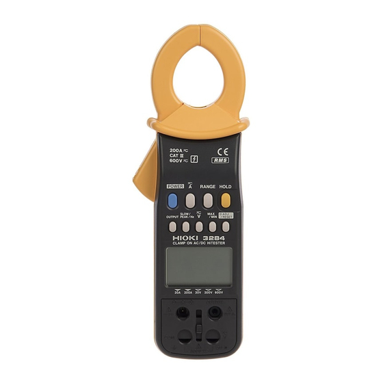
Page 19: Parts And Functions
――――――――――――――――――――――――――― 1.3 Parts and Functions Top and Side View ⑩ ⑰ ① ② ⑪ ③ ⑱ ④ ⑤ ⑥ ⑨ ⑧ ⑦ ⑫ ⑭ ⑯ ⑬ ⑮ ―――――――――――――――――――――――― Chapter 1 Product Outline... - Page 20 ――――――――――――――――――――――――――― ① POWER ・ Used to turn power on/off ・ To disable the auto power-off function, hold HOLD and press , when you turn power on. POWER ② ・ Switches current modes as follow. DCA ACA AC+DCA ③ RANGE ・ Switches between auto and manual ranges in measurements of current, voltage, or frequency.
- Page 21 ――――――――――――――――――――――――――― ⑥ SLOW/PEAK/Hz ・ SLOW slows down screen updating (once per three seconds). ・ FAST speeds up screen updating (four times per second). There isn't an annunciator " ". FAST Instead, the unit symbol blinks. ・ PEAK measures peak values (Peak Hold). ・...
- Page 22 ――――――――――――――――――――――――――― ⑨ 0ADJ/RESET ・ Performs auto-zero-adjustment in DC A, AC+DC A and DC V modes. ・ Resets data when measuring peak values. Reset all the data in a REC function. ・ If zero is not indicated under no input in the AC A, AC+DC A, AC V or AC+DC V modes, press , then press to perform a zero-...
- Page 23 ――――――――――――――――――――――――――― ⑫ Display (LCD) Direct Current (DC) Alternating Current (AC) Alternating Current and Direct Current (AC+DC) Auto-zero-adjustment or zero-cancel correction function is active Battery low warning Data hold function HOLD Waveform output (AC) is active Recording output (DC) is active Auto power off function AUTO Auto-range...
- Page 24 ――――――――――――――――――――――――――― Current hour 1 hour/segment (bar graph) 1 minute/segment (bar graph) Input over (bar graph) ⑬ Output terminal Connected to the optional 9094 output cord to provide output during a current measurement or a frequency measurement in a current mode. ⑭...
-
Page 25: Flowchart Of Key Operations
――――――――――――――――――――――――――― 1.4 Flowchart of Key Operations 1.4.1 Current Measurements Mode DC A AC A AC+DC A RANGE key AUTO range AUTO range AUTO range 20.00 A range 20.00 A range 20.00 A range 200.0 A range 200.0 A range 200.0 A range SLOW/PEAK/ SLOW SLOW... -
Page 26: Voltage Measurements Mode
――――――――――――――――――――――――――― 1.4.2 Voltage Measurements Mode V key DC V AC V AC+DC V RANGE key AUTO range AUTO range AUTO range 30.00 V range 30.00 V range 30.00 V range 300.0 V range 300.0 V range 300.0 V range 600 V range 600 V range 600 V range SLOW/PEAK/... -
Page 27: Frequency Measurements Mode
――――――――――――――――――――――――――― 1.4.3 Frequency Measurements Mode Current (AC A, AC+DC A) mode Voltage (AC V, AC+DC V) mode SLOW/PEAK/ SLOW FAST PEAK Hz key Current mode Voltage mode RANGE key AUTO range AUTO range 10.00 Hz range 10.00 Hz range 100.0 Hz range 100.0 Hz range 1000 Hz range 1000 Hz range... -
Page 28: Modes
――――――――――――――――――――――――――― 1.5 Modes For voltage and current, three modes are provided: DC (direct current, ), AC (alternating current, and AC+DC (alternating current and direct current, ) modes. Select a proper mode according to the waveform shown below: ―――――――――――――――――――――――― Chapter 1 Product Outline... - Page 29 ――――――――――――――――――――――――――― OUTPUT Input Mode Display (only for current mode) waveform ○Average value displayed (with polarity) Disabled X Not measurable ( ) X Not measurable X Not measurable (zero displayed) ○RMS value ( ) X Not measurable ○RMS value (without polarity) AC+DC ○RMS value (...
- Page 30 ――――――――――――――――――――――――――― ―――――――――――――――――――――――― Chapter 1 Product Outline...
-
Page 31: Chapter 2 Measurement Procedure
――――――――――――――――――――――――――― Chapter 2 Measurement Procedure 2.1 Preparations 1. Remove the rear cover and insert a battery. (Refer to "Chapter4 Battery Replacement".) 2. Press to turn the unit on. Verify that all POWER segments of the display light up briefly. Then the model name is shown, and the bar graph indicates the battery condition. -
Page 32: Current Measurement
――――――――――――――――――――――――――― 2.2 Current Measurement ・ Accurate measurement may be impossible in NOTE locations subject to strong external magnetic fields, such as transformers and high-current conductors, or in locations subject to strong external electric fields, such as radio transmission equipment. ・ Make sure that only one conductor is clamped in the center of the clamp sensor. -
Page 33: Measuring Ac Current (Ac A)
――――――――――――――――――――――――――― Wrong Measured conductor Current direction Current direction indicator ・ The DC A mode permits only DC current NOTE measurements that does not include the AC component (see 1.5: Modes). ・ The 20 A range will display up to 25 A, however, only the range from 1 A to 20 A can be displayed with guaranteed accuracy. -
Page 34: Measuring Ac/Dc Current (Ac+Dc A)
――――――――――――――――――――――――――― ・ Depending on ambient temperatures, the counter NOTE would not become zero under no input. If this happens, perform a zero-cancel correction (2.5.2: Zero-cancel correction function). ・ During a f.s. input, the measurement response speed is about 250 ms during rise (0% to 90%) and about 500 ms (100% to 10%) during fall (2.2.5, Figs. - Page 35 ――――――――――――――――――――――――――― 5. Open the top ends of the clamp core and clamp the measured conductor so that it passes through the center of the clamp core. ・ Just after suspension of input, or when modes are NOTE switched under no input, the counter would not become zero for about 10 seconds.
-
Page 36: Peak Hold Measurement
――――――――――――――――――――――――――― 2.2.4 Peak Hold Measurement 1. Press and select a measurement mode for the measured circuit. 2. In DC A and AC+DC A modes, make an auto-zero- adjustment by 0ADJ/RESET 3. Set to PEAK. The measurement mode is switched as follows. SLOW/PEAK/Hz SLOW FAST... -
Page 37: Output Function
――――――――――――――――――――――――――― ・ In case that the counter doesn't become zero under NOTE no input in peak measurement mode, even though you pressed to reset the peak data, the 0ADJ/RESET clamp sensor may be magnetized. Quit the peak measurement mode, and perform the auto-zero adjustment by . -
Page 38: Output Terminal
――――――――――――――――――――――――――― switches the output modes. OUTPUT REC (Record output) MON (Waveform output) Light turned off (Auto power-off inactive) (Auto power-off inactive) (Auto power-off active) 4. Set a range based on the unit's measurement range and other instruments, such as recorders. A conversion table for ranges is provided below. - Page 39 ――――――――――――――――――――――――――― outputs are analog outputs. The output ・ NOTE response time during a f.s. input differs between rise (0% to 90%, about 250 ms) and fall (100% to 10%, about 500 ms). (Figs 2 and 3) As the measured value is small to the range response time becomes long.
- Page 40 ――――――――――――――――――――――――――― GAIN [dB] AC+DC A (MON) AC A (MON) 100m 100k FREQUENCY [Hz] Fig. 1 Frequency Characteristics of Current Output ―――――――――――――――――――――――― Chapter 2 Measurement Procedure...
- Page 41 ――――――――――――――――――――――――――― Input wave Output wave 20 A 10 A 250 ms Fig. 2 Waveform of Output Response (Rise) Input wave Output wave 500 ms Fig. 3 Waveform of Output Response (Fall) ―――――――――――――――――――――――― Chapter 2 Measurement Procedure...
-
Page 42: Voltage Measurement
――――――――――――――――――――――――――― 2.3 Voltage Measurement 2.3.1 Measuring DC Voltage (DC V) 1. Press to display 2. Slide the slide cover up using the slide knob. Next, insert the red test lead to V and the black test lead to COM of the voltage measurement terminal. 3. -
Page 43: Measuring Ac Voltage (Ac V)
――――――――――――――――――――――――――― 2.3.2 Measuring AC Voltage (AC V) 1. Press to display 2. Slide the slide cover up using the slide knob. Next, insert the red test lead to V and the black test lead to COM of the voltage measurement terminal. 3. -
Page 44: Measuring Ac/Dc Voltage (Ac+Dc V)
――――――――――――――――――――――――――― 2.3.3 Measuring AC/DC Voltage (AC+DC V) 1. Press to display 2. Slide the slide cover up using the slide knob. Next, insert the red test lead to V and the black test lead to COM of the voltage measurement terminal. 3. -
Page 45: Peak Hold Measurement
――――――――――――――――――――――――――― ・ Every range will display up to 125% of the range, NOTE however, only the range from 10% to 100% can be displayed with guaranteed accuracy. ・ At any range, gross errors may occur at 1% or below of the range, whose accuracy is not guaranteed, as a result of internal corrective calculations. -
Page 46: Frequency Measurement
――――――――――――――――――――――――――― 2.4 Frequency Measurement 2.4.1 Frequency Measurement in Current Mode 1. Press and select AC or AC+DC, depending on the circuit to be measured. 2. If the current range of the measured circuit is known, set the current range to the manual range. switches the annunciators as SLOW/PEAK/Hz follows. -
Page 47: Frequency Measurement In Voltage Mode
――――――――――――――――――――――――――― ・ The 10 Hz range or 100 Hz range will display up to NOTE 125% of each range, however, only the range from 10% to 100% can be displayed with guaranteed accuracy. does not affect output values. ・ MAX/MIN ・... -
Page 48: Output Function For Frequency
――――――――――――――――――――――――――― ・ At the 100 Hz and 1000 Hz ranges, ---- appears on NOTE the counter when the frequency is lower than 10 Hz. ・ ---- appears on the counter, if the frequency is lower than 1 Hz. ・ O. L. appears on the counter, if the frequency is higher than 1 kHz. - Page 49 ――――――――――――――――――――――――――― 2. Press annunciator lights and OUTPUT activates the output function. 3. The auto power-off function is automatically disabled. ( annunciator is tuned off.) 4. Set a range based on the unit's measurement range and other instruments, such as recorders. Range/DIV 10 mV 20 mV 50 mV 0.1 V 0.2 V 0.5 V 1000 Hz range...
-
Page 50: Auto-Zero-Adjustment/Zero-Cancel Correction Function
――――――――――――――――――――――――――― ・ For a long term measurement, use the optional NOTE 9445-02 or 9445-03 AC ADAPTER. ・ When the AC adapter is used and there is a large amount of noise in the power line, the display may show several counts or noise may be present in the output. -
Page 51: Zero-Cancel Correction Function
――――――――――――――――――――――――――― ・ Do not perform auto-zero adjustment when using NOTE auto range in the DC V mode. Always switch to the range you will use (a manual range) before performing the adjustment. 2.5.2 Zero-Cancel Correction Function Use the zero-cancel correction function when the counter fails to become zero under no input in AC A, AC+DC A, AC V, or AC+DC V mode. -
Page 52: Alteration Of Counter Updates
――――――――――――――――――――――――――― If you press during the data hold function, RANGE the bar graph display the present range. 2.7 Alteration of Counter Updates The counter is updated twice per second when powering on. The counter update may be altered according to measurement conditions. changes an annunciator as SLOW/PEAK/Hz follows:... - Page 53 ――――――――――――――――――――――――――― and minimum measured values and maximum/minimum averages. 1. Measurement indicated value Pressing the key during measurements of MAX/MIN current or voltage activates the recording function. REC flashes and the product saves the maximum value (MAX), minimum value (MIN), and average value (AVE) in internal memory from the instant you press the key.
- Page 54 ――――――――――――――――――――――――――― When "min" is shown in the right-hand corner of the bar graph, each segment of the bar graph corresponds to one minute. Every time one minute elapses, one segment of the flashing bar graph goes on. When all segments on the bar graph go on, the elapsed time is 30 minutes.
- Page 55 ――――――――――――――――――――――――――― 3. Deactivation of Recording Function Pressing the key deactivates the recording HOLD function. goes on, stops flashing and HOLD goes on, and the elapsed time stops incrementing. While the recording function is being deactivated, data is not updated, even if the clamp sensor is disconnected from the conductor.
-
Page 56: Auto Power-Off Function Aps
――――――――――――――――――――――――――― ・ When you need minimum value and average value NOTE data, make sure to activate the recording function during measurement. If the function is activated when there is no input, the minimum value will remain zero. Also, when deactivating the recording function, press the key to terminate HOLD... -
Page 57: Battery Low Warning
――――――――――――――――――――――――――― 2.10 Battery Low Warning ・ When this indication appears, the battery is depleted, which can lead to inaccurate measurements. Replace the battery to ensure accuracy. ・ To check remaining battery life, check the bar graph, when powering on or by pressing . - Page 58 ――――――――――――――――――――――――――― ―――――――――――――――――――――――― Chapter 2 Measurement Procedure...
-
Page 59: Chapter 3 Specifications
――――――――――――――――――――――――――― Chapter 3 Specifications 3.1 Measurement Specifications Temperature and humidity for 9 ), guaranteed accuracy 80% RH or less Guaranteed accuracy period 1 year, or opening and closing of the Clamp Sensor 10,000 times, whichever comes first 3.1.1 Current Measurement Specifications ○... - Page 60 ――――――――――――――――――――――――――― Range 10~45,66~1kHz 1kHz~2kHz Resolution (Accuracy Range) 0.1A (2.0%rdg.+7dgt.) (4.0%rdg.+7dgt.) 200A(100.0~200.0A) ○ Output accuracy ① DC current A (mean value) Range (Accuracy Range) 20A(1.00~20.00A) 1V/f.s. (1.3%rdg.+5mV) 200A(10.0~200.0A) 1V/f.s. (1.3%rdg.+5mV) ② AC current Arms (true rms) Range 45~66Hz 10~45,66~2kHz (Accuracy Range) 20A(1.00~20.00A) AC1V/f.s.
- Page 61 ――――――――――――――――――――――――――― Range 10~45,66~1kHz 1kHz~2kHz (Accuracy Range) DC1V/f.s. (2.0%rdg.+10mV) (4.0%rdg.+10mV) 200A(100.0~200.0A) Output response (during a f.s. input): Rise response time (0% to 90%) 250 ms or less Fall response time (100% to 10%) 500 ms or less ③ AC+DC current Arms (true rms) Range DC,45~66Hz 10~45,66~2kHz...
- Page 62 ――――――――――――――――――――――――――― ○ Peak measurement accuracy (Peak hold function) During continuous input of sine waves ① DC current A peak (wave peak value) Range Resolution (Accuracy Range) 20A(1.0~50.0A) 0.1A (1.3%rdg.+7dgt.) 200A(10.0~300.0A) 0.1A (1.3%rdg.+7dgt.) ② AC current A peak (wave peak value) Range 45~66Hz 10~45,66~2kHz...
- Page 63 ――――――――――――――――――――――――――― Output accuracy Range (Accuracy Range) DC1V/f.s. (1.3%rdg.+3mV) 10Hz(1.00~10.00Hz) DC1V/f.s. (1.3%rdg.+3mV) 100Hz(10.0~100.0Hz) DC1V/f.s. (2.0%rdg.+3mV) 1000Hz(100~1000Hz) Output response: 4 seconds or less at 1000Hz and 100Hz ranges, 6 seconds or less at 10Hz range Current Specifications Maximum permissible 200 Arms continuous, 300 Amax. current See Fig.4 Effect of conductor...
-
Page 64: Voltage Measurement Specifications
――――――――――――――――――――――――――― 3.1.2 Voltage Measurement Specifications ○ Voltage display accuracy ① DC voltage V (mean value) Range Resolution (Accuracy Range) 30V(3.00~30.00V) 0.01V (1.0%rdg.+3dgt.) 300V(30.0~300.0V) 0.1V (1.0%rdg.+3dgt.) 600V(60~600V) (1.0%rdg.+3dgt.) ② AC voltage Vrms (true rms) Range 45~66Hz 10~45,66~1kHz Resolution (Accuracy Range) 30V(3.00~30.00V) 0.01V (1.0%rdg.+3dgt.) (1.5%rdg.+5dgt.) - Page 65 ――――――――――――――――――――――――――― ③ AC+DC voltage V peak (wave peak value) Range DC,45~66Hz 10~45,66~1kHz Resolution (Accuracy Range) 30V(3.0~75.0V) 0.1V (1.0%rdg.+7dgt.) (1.5%rdg.+7dgt.) 300V(30~750V) (1.0%rdg.+7dgt.) (1.5%rdg.+7dgt.) 600V(60~1000V) (1.0%rdg.+7dgt.) (1.5%rdg.+7dgt.) ○ Frequency measurement Hz Display accuracy Range Resolution (Accuracy Range) 0.01Hz (0.3%rdg.+1dgt.) 10Hz(1.00~10.00Hz) 0.1Hz (0.3%rdg.+1dgt.) 100Hz(10.0~100.0Hz) (1.0%rdg.+1dgt.) 1000Hz(100~1000Hz)
-
Page 66: General Specifications
――――――――――――――――――――――――――― 3.2 General Specifications ○ Accessory Functions: Auto-zero adjustment Pressing 0ADJ/RESET once in DC A or function AC+DC A mode. Zero cancel function Pressing 0ADJ/RESET once with holding HOLD in AC or AC+DC mode. Recording Maximum (MAX), minimum (MIN), average (AVE) value display selectable for current, voltage and frequency measurements Data hold... - Page 67 ――――――――――――――――――――――――――― Display response time Current, Voltage: 1 s max. (the range is fixed, Frequency: 0% to 100%) 1 s max. (1000 Hz, 100 Hz range) 2.5 s max. (10 Hz range) Range switching Auto range, manual (fixed) range (selectable). Output impedance 300Ω...
- Page 68 ――――――――――――――――――――――――――― Storage temperature -10 to 50 range (14 to 122 , no condensation) Power source One 6F22 (006P) 9 V battery or 9445-02 AC ADAPTER (SA10-0910N, SINO- AMERICAN) or 9445-03 AC ADAPTER (EU) (SA10-0910G, SINO-AMERICAN) (option) Maximum power 110 mVA consumption Battery life Approx.
-
Page 69: Chapter 4 Battery Replacement
――――――――――――――――――――――――――― Chapter 4 Battery Replacement CAUTION Do not fix the back casing screws too tightly. The torque about 0.5N・m is recommended. 1. Remove the two fastening screws of the rear cover, using a Phillips screwdriver. 2. Remove the rear cover. 3. - Page 70 ――――――――――――――――――――――――――― ―――――――――――――――――――――――― Chapter 4 Battery Replacement...
-
Page 71: Chapter 5 Ac Adapter (Optional)
――――――――――――――――――――――――――― Chapter 5 AC Adapter (Optional) Fully insert the optional 9445-02 AC ADAPTER into the AC adapter connection terminal. ・ The adapter may be used either with or without a NOTE battery. ・ Use of a battery enables continuous measurement if the AC power source temporarily becomes unavailable, due to a blackout or some other reason. - Page 72 ――――――――――――――――――――――――――― All the phenomena are likely to happen, in the case NOTE the battery voltage is lower than AC adapter voltage (typ. 9 V) . It is recommended that a new battery should be used, when the blackout seems to be short.
-
Page 73: Chapter 6 Attaching The Hand Strap
――――――――――――――――――――――――――― Chapter 6 Attaching The Hand Strap Explains how to attach the hand strap, for easy handling of the unit in the field. ―――――――――――――――――――――――― Chapter 6 Attaching The Hand Strap... - Page 74 ――――――――――――――――――――――――――― ―――――――――――――――――――――――― Chapter 6 Attaching The Hand Strap...
-
Page 75: Chapter 7 Troubleshooting
――――――――――――――――――――――――――― Chapter 7 Troubleshooting If the unit seems not to be working normally, check the following points first before requesting service. Symptom Battery Battery clip Test leads Unit does not come indication appears and unit immediately turns off. indication appears. Unit turns off during use.* Voltage cannot be... - Page 76 ――――――――――――――――――――――――――― ○ If no power is supplied: ・ If you're using a battery, check that it has sufficient remaining power. (See 2.1: Preparations ) ・ If you're using the AC adapter, check that it's fully inserted into the AC adapter terminal and socket. ・...
- Page 77 ――――――――――――――――――――――――――― ○ The measured value is smaller than the estimated value. Current measurement: ・ Check that the clamp sensor is firmly closed. ・ Check that the frequency of the measured circuit is within the range provided in the specifications. (A smaller value will be displayed for a high inverter carrier frequency.) ・...
- Page 78 ――――――――――――――――――――――――――― Voltage measurement: ・ Check that the test leads are fully connected. ・ Check that the frequency of the measured circuit is within the range provided in the specifications. ・ Check that the proper steps have been taken, according to the procedure described in 2.5.1: Auto-zero adjustment function and 2.5.2: Zero-cancel correction function.
- Page 79 ――――――――――――――――――――――――――― ○ The measured value is larger than the estimated value. Current measurement: ・ Check that you're using the proper range. ・ Examine the waveform using output function to confirm that no components but the estimated frequency are being used. ・...
- Page 80 ――――――――――――――――――――――――――― ○The output value is smaller than the estimated value. ・ Take the same precautionary steps as for the measured value on the counter. ・ Make sure the 9094 OUTPUT CORD is fully connected. ・ Make sure you've selected the proper output mode ( ・...
-
Page 81: Chapter 8 Service
・ If the unit is not functioning properly, check the battery. If a problem is found, contact your dealer or HIOKI representative. Pack the unit carefully so that it will not be damaged during transport, and write a detailed description of the problem. HIOKI cannot bear any responsibility for damage that occurs during shipment. - Page 82 ――――――――――――――――――――――――――― ―――――――――――――――――――――――― Chapter 8 Service...
- Page 85 HIOKI 3284 CLAMP ON AC/DC HiTESTER Instruction Manual Publication date: September 2006 Revised edition 10 Edited and published by HIOKI E.E. CORPORATION Technical Sales Support Section All inquiries to Sales and Marketing International Department 81 Koizumi, Ueda, Nagano, 386-1192, Japan TEL: +81-268-28-0562 / FAX: +81-268-28-0568 E-mail: os-com@hioki.co.jp...
- Page 86 HEAD OFFICE 81 Koizumi, Ueda, Nagano 386-1192, Japan TEL +81-268-28-0562 / FAX +81-268-28-0568 E-mail: os-com@hioki.co.jp/ URL http://www.hioki.co.jp/ HIOKI USA CORPORATION 6 Corporate Drive, Cranbury, NJ 08512, USA TEL +1-609-409-9109 / FAX +1-609-409-9108 Printed on recycled paper...
Need help?
Do you have a question about the 3284 and is the answer not in the manual?
Questions and answers