Advertisement
Quick Links
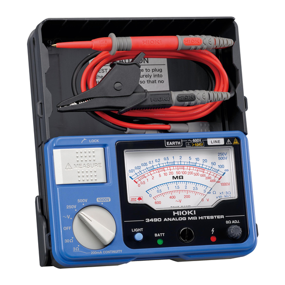
3490
ANALOG M
HiTESTER
(Insulation and Continuity Tester)
Instruction Manual
February 2015 Revised edition 10
Printed in Japan
3490A981-10 15-02H
Warranty
Warranty malfunctions occurring under conditions of normal use in con-
formity with the Instruction Manual and Product Precautionary Mark-
ings will be repaired free of charge. This warranty is valid for a period
of three (3) years from the date of purchase. Please contact the dis-
tributor from which you purchased the product for further information on
warranty provisions.
Introduction
Thank you for purchasing the HIOKI Model 3490 ANALOG M
HiTESTER. To obtain maximum performance from the instrument,
please read this manual first, and keep it handy for future refer-
ence.
Overview
The 3 range of this instrument can be used for both the Continuity
Test on protective conductors used in electrical installations of build-
ings, and the protective conductor resistance measurement test ap-
proved by IEC60364.
The 30 range is also optimal for the Polarity and Circuit Connection
Testing for Indoor Wiring approved by AS/NZS3017, guidelines for
tests and inspections on electrical installations in the Oceania region.
This instrument is not designed for the production line and is not suit-
able for that purpose. Please use the 3154 Digital M HiTester for the
production line.
Inspection and Maintenance
Initial Inspection
When you receive the instrument, inspect it carefully to ensure that no
damage occurred during shipping. If damage is evident, or if it fails to
operate according to the specifications, contact your dealer or Hioki
representative.
Maintenance and Service
• To clean the instrument, wipe it gently with a soft cloth moistened
with water or mild detergent. Never use solvents such as benzene,
alcohol, acetone, ether, ketones, thinners or gasoline, as they can
deform and discolor the case.
• If the instrument seems to be malfunctioning, contact your dealer or
Hioki representative.
• Pack the instrument so that it will not sustain damage during
shipping, and include a description of existing damage. We cannot
accept responsibility for damage incurred during shipping.
Safety
This manual contains information and warnings essential for safe oper-
ation of the instrument and for maintaining it in safe operating condition.
Before using it, be sure to carefully read the following safety precautions.
This instrument is designed to comply with IEC 61010
Safety Standards, and has been thoroughly tested for
safety prior to shipment. However, mishandling during
use could result in injury or death, as well as damage to
the instrument. Be certain that you understand the
instructions and precautions in the manual before use.
We disclaim any responsibility for accidents or injuries
not resulting directly from instrument defects.
Safety Symbol
In the manual, the
symbol indicates particularly impor-
tant information that the user should read before using the
instrument. The
symbol printed on the instrument indi-
cates that the user should refer to a corresponding topic in
the manual (marked with the
symbol) before using the
relevant function.
Indicates that dangerous voltage may be present at this
terminal.
Indicates a double-insulated device.
Indicates AC (Alternating Current).
Indicates DC (Direct Current).
The following symbols in this manual indicate the relative
importance of cautions and warnings.
Indicates that incorrect operation presents an extreme haz-
ard that could result in serious injury or death to the user.
Indicates that incorrect operation presents a significant haz-
ard that could result in serious injury or death to the user.
Indicates that incorrect operation presents a possibility of
injury to the user or damage to the instrument.
Indicates advisory items related to performance or cor-
rect operation of the instrument.
Other Symbol
Indicates a prohibited action.
This symbol indicates that the product conforms to regula-
tions set out by the EC Directive.
Measurement categories
This instrument complies with CAT III safety requirements.
To ensure safe operation of measurement instruments, IEC 60664
establishes safety standards for various electrical environments, cate-
gorized as CAT II to CAT IV, and called overvoltage categories. These
are defined as follows.
CAT II :Primary electrical circuits in equipment connected to an AC
electrical outlet by a power cord (portable tools, household
appliances, etc.). CAT II covers directly measuring electrical
outlet receptacles.
CAT III:Primary electrical circuits of heavy equipment (fixed installa-
tions) connected directly to the distribution panel, and feeders
from the distribution panel to outlets.
CAT IV:The circuit from the service drop to the service entrance, and
to the power meter and primary overcurrent protection device
(distribution panel).
Using a measurement instru-
ment in an environment desig-
nated with a higher-numbered
category than that for which the
instrument is rated could result in
a severe accident, and must be
carefully avoided.Use of a mea-
surement instrument that is not
CAT-rated in CAT II to CAT IV
measurement applications could result in a severe accident, and must
be carefully avoided.
Usage Notes
Follow these precautions to ensure safe operation and to obtain the full
benefits of the various functions.
Preliminary Checks
Before using the instrument the first time, verify that it operates normal-
ly to ensure that no damage occurred during storage or shipping. If you
find any damage, contact your dealer or Hioki representative.
• 1000 V or 600 V may be labeled depending on the supplied
test leads, but this is the rating of the test lead and not the
rating performance of the 3490. Please refer to the Specifi-
cations for the rating performance of this instrument.
• Before attaching to or removing the test lead from the
instrument, please remove the Test Lead from the tested
objected and turn the function switch to OFF.
• Do not use the instrument where it may be exposed to corro-
sive or combustible gases. The instrument may be damaged or
cause an explosion.
• Do not use the instrument where it may be exposed to oil,
chemicals, or solvents. Contact with these substances may
cause cracking in the instrument, resulting in damage or elec-
tric shock.
• Do not allow the instrument to get wet, and do not take mea-
surements with wet hands. This may cause an electric shock.
• Please only use batteries for electrical supply. Any other elec-
trical supply may damage the instrument and tested object
and cause electric shock.
• Before using the instrument, make sure that the insulation on
the test leads is undamaged and that no bare conductors are
improperly exposed. Using the instrument in such conditions
could cause an electric shock, so contact your dealer or Hioki
representative for replacements.
• This instrument is designed for use indoors. It can be operated at
temperatures between 0 and 50°C without degrading safety.
• Do not store or use the instrument where it could be exposed to di-
rect sunlight, high temperature or humidity, or condensation. Under
such conditions, the instrument may be damaged and insulation
may deteriorate so that it no longer meets specifications.
• To prevent accidents, please use the supplied L9787 Test Leads (or
the optional L9788-10).
• To avoid damage to the instrument, protect it from physical shock
when transporting and handling. Be especially careful to avoid phys-
ical shock from dropping.
• If the protective functions of the instrument are damaged, either re-
move it from service or mark it clearly so that others do not use it in-
advertently.
• Although this instrument is dust resistant, it is not completely dust-
or waterproof. To prevent possible damage, avoid using in dusty or
wet environments.
• The protection rating for the enclosure of this device (based on
EN60529) is *IP40.
• Removable sleeves are attached to the metal pins at the ends of the
test leads. To prevent a short circuit accident, be sure to use the test
leads with the sleeves attached when performing measurements in
the CAT III measurement category. Remove the sleeves from the
test leads when performing measurements in the CAT II measure-
ment category. For details on measurement categories, see "Mea-
surement categories" in the instruction manual.
• When performing measurements with the sleeves attached, be care-
ful to avoid damaging the sleeves. If the sleeves are inadvertently
removed during measurement, be especially careful in handling the
test leads to avoid electric shock.
• To prevent an electric shock accident, confirm that the white or red
portion (insulation layer) inside the cable is not exposed. If a color
inside the cable is exposed, do not use the cable.
*IP40
4: Protected against access to hazardous parts with wire measuring 1.0 mm in diameter.
The equipment inside the enclosure is protected against entry by solid foreign objects
larger than 1.0 mm in diameter.
0: The equipment inside the enclosure is not protected against the harmful effects of water.
• To avoid battery depletion, turn the function selector OFF after use. Battery
may drain if the switch is not turned to OFF.
• The test lead plug comes with a protective cap. Please remove this cap
before attaching it to the instrument.
• After measurement, please turn the function switch to OFF. The cover will not
close if the switch is not at OFF.
Specifications
Standard Specifications
• Insulation Resistance measurement:
DC voltage supply, current detection
• Low resistance measurement:
DC current supply, voltage detection
Functions
• AC Voltage measurement: Average responding type
• Effective battery range indicator: Built-in battery power indicator
• Live circuit indicator: lights up when voltage is detected
between LINE terminal and EARTH terminal
Automatically discharges the electric charge still present in
Automatic electric discharge
the capacitance of the test object after the Insulation resis-
tance measurement test.
When the function switch is not at OFF, the power will only
Auto Power Save
go off automatically 15 minutes after the last live circuit
alert has been displayed.
Indicator: Meter (Internal magnet type taut band method)
Indicator light
• Light device: LED
Indicator
• Light automatic OFF function: Light goes off about 3 min-
utes after MEASURE key is switched to OFF or when
LIGHT key is pressed.
General Specifications
Guaranteed accuracy period
1 year
0 to 40C (32 - 104F), 90%RH or lower (non-condensating)
Operating Temperature &
40 to 50C (104 - 122F), at 50C and below relative with
Humidity
linear decrease up to 50%RH
Operating Environment
Indoors, Pollution Degree 2, Altitude up to 2000 m (6562-ft.)
Storage Temperature &Humidity 0 to 50C (32 - 122F), 90%RH or lower (non-condensating)
Degree of protection
IP40
Maximum rated voltage to
600 V AC (AC voltage function)
terminal
Maximum rated voltage to
600 V AC, Measurement Category III,
earth
Anticipated Transient Overvoltage: 6000 V
7060 V AC, 50 Hz/60 Hz, Measurement terminals - electri-
Dielectric strength
cal enclosure, during 1 minute, current sensitivity 1 mA
Power source
Rated power voltage: 1.5 V DC × 4, LR6 alkaline battery × 4
Maximum rated power
3 VA
Continuous operating time
Approx. 20 hours (at 500 V range, no load)
Drop Proof
On concrete: 1 m/1 time
Dimensions
Approx. 159W×177H×53D mm (6.26"W×6.97"D×2.09"D)
(excluding protrusions)
Approx. 610g (21.5oz)
Mass
(including battery, not including test lead)
L9787 Test Lead, Instruction manual, Shoulder strap,
Accessories
LR6 alkaline battery × 4
FF0.5AH/ 1000 V (70 172 40.0.500: SIBA) (Very fast act-
Replacements
ing, arc extinction type, high rupturing capacity type)
L9788-10 Test Lead with Remote Switch (Red)
Options
L9787-91 Breaker Pin, L9788-92 Breaker Pin,
9804-02 Magnetic Adapter
Safety EN61010
EMC
EN61326
Measuring equipment for Low voltage distribution system
Standards
EN61557-1/-2/-4* (the 3
is applicable to part 4)
*Subclause 4.3 of Part 4 (Interchanging of test leads) is not
applicable when the L9788-10 is used.
Measurement functions
Guaranteed for one year at 23C±5C (73F ±9F) and 90% RH.
Insulation Resistance Measurement
Rated output voltage
250 VDC
500 VDC
Effective maximum
100 M
indicated value
Center scale value
1 M
Response time
Within 3 sec. (
center value,
1000 times
1000 times
Possible number of
measurements
(at 0.25 M
(at 0.5 M
Effect of position
±2% of scale length
(Horizontal ±90)
Overload protection
660 VAC (10 sec.)
Accuracy
0.05 to 50 M
2 to 1000 M
1st effective
measuring range
±2% of scale length
0.01 to 0.05 M
2nd effective
50 to 100 M
1000 to 4000 M
measuring range
±2% of scale length
0 M,
scale
±2% of scale length
Measurement terminal voltage characteristic
Open circuit voltage
1 to 1.2 times of rated output voltage
(when no load is applied)
Lower limit measurement
resistance value to be
0.25 M
0.5 M
maintained rated
output voltage
1 mA (Tolerance: 1 to 1.2 times of the rating value)
Rated current
(The current flow when rated output voltage is maintained)
Short circuit current
1.2 mA max.
Effect of temperature
1000 VDC
4000 M
50 M
0 M)
1000 times
(at 1 M
0.5 to 2 M
1 M
Advertisement

Related Manuals for Hioki 3490


Summary of Contents for Hioki 3490
- Page 1 • Effective battery range indicator: Built-in battery power indicator (Insulation and Continuity Tester) rating performance of the 3490. Please refer to the Specifi- • Live circuit indicator: lights up when voltage is detected Safety Standards, and has been thoroughly tested for between LINE terminal and EARTH terminal cations for the rating performance of this instrument.
- Page 2 There is a light at the tip which can be switched on measured. measuring range Please replace the batteries then. by pressing the LIGHT key on the 3490. Earth side lead is 3. Connect the red test lead to the line to be measured. • Auto power save (power-saving function) ...
Need help?
Do you have a question about the 3490 and is the answer not in the manual?
Questions and answers