Table of Contents
Advertisement
Quick Links
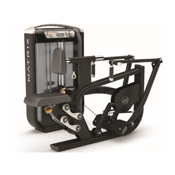
G7-S34 Seated Row
2.1 Important Safety Information .................................................................................................... 3
2.2 Check for Damaged Parts......................................................................................................... 3
3.1 Preventative Maintenance Checklist.......................................................................................... 4
3.2 Repetition Counter Info.............................................................................................................. 4
4.1 G7-S34 Seated Row.................................................................................................................. 6
5.1 G7-S34 Seated Row Assembly Instructions.............................................................................. 7
6.1 Troubleshooting - Repetition Counter Issues............................................................................ 12
6.2 Troubleshooting - Incremental Weight Pin Issues..................................................................... 14
6.3 Troubleshooting - Arms are uneven......................................................................................... 15
6.4 Troubleshooting - Weight Stack Pin Issues............................................................................... 16
6.5 Troubleshooting - Cable is Failing off a Pulley or CAM ...................................................17
6.6 Troubleshooting - Cable Jacket is Failing......................................................................18
6.7 Troubleshooting - Repetition Counter Magnet Missing or Failing off....................................19
6.8 Troubleshooting - ROM Plunger or Pull Pins Do Not Move Easily.......................................19
6.9 Troubleshooting - Seat Loose or Will Not Spring Up.........................................................20
6.10 Troubleshooting - Seat Failing....................................................................................21
7.1 Testing the Unit ........................................................................................................................... 22
7.2 Aluminum Wing Replacement...................................................................................................... 22
7.3 Top Cover Replacement.............................................................................................................. 23
7.4 Repetition Counter Replacement................................................................................................. 24
Service manual
Table of Contents
....................................................................................
2
1
Advertisement
Table of Contents
Troubleshooting

Related Manuals for Matrix G7-S34


Summary of Contents for Matrix G7-S34
-
Page 1: Table Of Contents
3.2 Repetition Counter Info......................4 CHAPTER4: Product specification& warranty information 4.1 G7-S34 Seated Row........................6 CHAPTER5: Assembly instructions 5.1 G7-S34 Seated Row Assembly Instructions................7 CHAPTER6: Troubleshooting 6.1 Troubleshooting - Repetition Counter Issues................12 6.2 Troubleshooting - Incremental Weight Pin Issues..............14 6.3 Troubleshooting –... -
Page 2: Chapter1: Serial Number Location
7.5 Weight Stack Shroud Replacement..................... 25 7.6 Repetition Sensor Replacement....................26 7.7 Incremental Weight Pin Replacement..................27 7.8 Weight Plate Replacement......................29 7.9 Weight Stack Pulley Assembly Replacement................31 7.10 Hand Grip Replacement......................32 7.11 Seat Pad Adjustment Handle Replacement……………............32 7.12 Head Pad Replacement...................... -
Page 3: Chapter2: Important Safety Instructions
CHAPTER2: Important Safety instructions 2.1 Important Safety Information It is the sole responsibility of the purchaser of Matrix Fitness Systems products to instruct all individuals, whether they are the end user or supervising personnel on proper usage of the equipment. -
Page 4: Chapter3: Preventative Maintenance
CHAPTER3: Preventative Maintenance 3.1 Preventative Maintenance Checklist Preventative maintenance and daily cleaning will prolong the life and look of your Matrix Fitness Systems equipment. ACTION FREQUENCY Clean Upholstery Daily Inspect Cables Daily Clean Guide Rods Monthly Inspect Hardware Monthly Inspect Frame... - Page 5 digits of the accrued hours of use are shown (Figure C). 7) After 3 seconds, if there are more digits in the accrued hours, the rep counter will switch to c1 (Figure D). 8) Combine the c values to determine the accrued hours. Using Figures C & D below, the unit would have 1,209 accrued hours.
-
Page 6: Chapter4: Product Specification& Warranty Information
CHAPTER4: PRODUCT SPECIFICATION & WARRANTY INFORMATION G7-S34 Seated Row TECHNICAL SPECIFICATIONS Overall Dimensions (L x W x H) 64"L x 48"W x 52H" Weight 646 lbs. Shipping Weight 693 lbs. WARRANTY Frame (not coatings) 10 years Weight Stacks 5 years... -
Page 7: Chapter5: Assemblyinstructions
CAUTION The weight of the Matrix Fitness Systems Seated Row is 350 lbs (159 kg) not including the weight stack. The weight stack tower is packaged completely assembled for ease of installation; use extra caution when removing the unit from its pallet during assembly. - Page 8 G7-S34 Seated Row Assembly instructions- Continued Step1 Step2...
- Page 9 Step3 Step4...
- Page 10 Step5 Step6...
- Page 11 Step7...
-
Page 12: Chapter6: Troubleshooting
CHAPTER6: Troubleshooting 6.1 Troubleshooting – repetition counter issues THE REPETITION IS BLANK OR IS NOT COUNTING MOVEMENTS. Possible Causes 1) The rep counter battery is dead or disconnected. 2) The rep counter is unplugged from the repetition sensors. 3) The magnet is missing or miss-positioned. 4) The repetition sensors are faulty or miss-positioned. - Page 13 6.1 Troubleshooting – repetition counter issues - CONTINUED...
-
Page 14: Troubleshooting - Incremental Weight Pin Issues
6.2 Troubleshooting - incremental weight pin issues INCREMENTAL WEIGHT PIN IS LOOSE OR FEELS SLOPPY Possible causes 1) The snap ring holding the incremental weight pin in position is damaged or missing. 2) The incremental weight pin is damaged. Solution 1) Remove the weight stack covers. -
Page 15: Troubleshooting - Arms Are Uneven
6.3 Troubleshooting - arms ARMS ARE NOT EVEN AT THE STARTING POSITION Possible Causes 1) The arm tie rods are uneven. 2) The arms are bent or uneven. 3) The frame is bent or uneven. Solution 1) The tie rods on the Shoulder Press, Chest Press, Lat Pull Down and Seated Row are adjustable. a. -
Page 16: Troubleshooting - Weight Stack Pin Issues
6.4 Troubleshooting - weight stack pin issues WEIGHT STACK PIN WILL NOT GO INTO SOME OR ALL WEIGHT PLATES Possible Causes 1) The weight stack pin is bent. 2) The cable is attached too loosely or too tightly. 3) The weight plates are not seated correctly at the bottom of the guide rods. 4) The top weight plate bushings are damaged. -
Page 17: Troubleshooting - Cable Is Failing Off A Pulley Or Cam
6.5 Troubleshooting - cable is failing off a pulley or cam THE WEIGHT STACK CABLE IS FALLING OFF A PULLEY OR CAM Possible Causes 1) The cable is too loose or too tight. 2) The cable is routed incorrectly. 3) A cable retainer needs to be added to the Hip Abductor, Hip Adductor and Leg Press (See Sections 6.6 and 6.7). -
Page 18: Troubleshooting - Cable Jacket Is Failing
6.6 Troubleshooting - cable jacket is failing... -
Page 19: Troubleshooting - Repetition Counter Magnet Missing Or Failing Off
ROM PLUNGER OR PULL PINS DO NOT MOVE EASILY Possible Causes 1) The pins are rubbing on the frame creating friction. Solution 1) Remove the affected pin, add grease (Matrix recommends SuperLube brand grease with PTFE) and then re-install the pin. -
Page 20: Troubleshooting - Seat Loose Or Will Not Spring Up
6.9 Troubleshooting - seat loose or will not spring up SEAT IS TOO LOOSE OR NOT SPRINGING UP Possible Causes 1) The swirl springs are miss- positioned or missing from the connecting rods. 2) The swirl springs are broken in the connecting rods. Solution 1) Remove the bottom seat connecting bars (Figures A &... -
Page 21: Troubleshooting - Seat Failing
6.10 Troubleshooting - seat failing SEAT IS FALLING WHEN A USER SITS ON IT Possible Causes 1) The seat pin is oriented in the wrong direction. Solution 1) Remove the plastic portion of the seat front (4 screws). 2) Remove the cotter pin holding the seat pin assembly to the seat frame. 3) Flip the seat pin and re-assemble the seat. -
Page 22: Chapter7: Part Replacement Instructions
CHAPTER7: Part Replacement Instructions 7.1 Testing the unit Once the unit or replacement part*** is fully installed and assembled and properly placed on the floor, use the following instructions to test the machine: ***NOTE- Not all of the replacement instructions will apply to every model. 1) Check that the weight stack pin will slide freely into the weight stack at all positions. -
Page 23: Top Cover Replacement
7.3 Top cover replacement 1) Remove the 4 screws going through the aluminum wing into the top cover of the weight stack (Fig A). 2) Disconnect the repetition counter wire and remove the aluminum wing and top cover from the weight stack (Figure B). -
Page 24: Repetition Counter Replacement
7.4 Repetition counter replacement 1) Remove the 4 screws going through the aluminum wing into the top cover of the weight stack (Figure A). 2) Disconnect the repetition counter wire and remove the aluminum wing and top cover from the weight stack (Figure B). -
Page 25: Weight Stack Shroud Replacement
7.5 Weight stack shroud replacement 1) Remove the 4 screws going through the aluminum wing into the top cover of the weight stack (Fig A). 2) Disconnect the repetition counter wire and remove the aluminum wing and top cover from the weight stack (Figure B). -
Page 26: Repetition Sensor Replacement
7.6 Repetition sensor replacement 1) Remove the 4 screws going through the aluminum wing into the top cover of the weight stack (Figure A). 2) Disconnect the repetition counter wire and remove the aluminum wing and top cover from the weight stack (Figure B). -
Page 27: Incremental Weight Pin Replacement
7.7 Incremental weight pin replacement 1) Remove the weight stack shrouds as outlined in Section 7.5. 2) Remove the 4 screws holding on the clear plastic cover over the incremental weight pin and remove it (Figures A & B). 3) Remove the 2 screws holding on the reaction block and remove it (Figures C & D). 4) Remove the snap ring holding the incremental weight pin to the top weight plate and remove the incremental weight pin (Figures E, F, &... - Page 28 7.7 Incremental weight pin replacement- CONTINUED...
-
Page 29: Weight Plate Replacement
7.8 Weight plate replacement 1) Remove the weight stack shrouds as outlined in Section 7.5. 2) Remove the 4 screws holding on the clear plastic cover over the incremental weight pin and remove it (Figures A & B). 3) Remove the 2 screws holding on the reaction block and remove it (Figures C & D). 4) Move the rubber cover on the cable by pulling up on it (Figure E). - Page 30 7.8 Weight plate replacement- Continued...
-
Page 31: Weight Stack Pulley Assembly Replacement
7.9 Weight stack pulley assembly replacement 1) Remove the weight stack shrouds as outlined in Section 7.5. 2) Remove the 4 screws holding on the clear plastic cover over the incremental weight pin and remove it (see Section 7.8 for pictures). 3) Move the rubber cover on the cable by pulling up on it (Figure A). -
Page 32: Hand Grip Replacement
7.10 Hand grip replacement 1) Remove the 2 set screws holding the hand grip end cap to the frame (Figure A). 2) Remove the hand grip end cap (Figure B). 3) Loosen the screw holding together the hand grip bottom end cap (Figure C). 4) Pull and remove the rubber hand grip and bottom end cap (Figure D). -
Page 33: Head Pad Replacement
7.12 Head pad replacement 1) Remove the 2 screws holding the head pad / back cover to the frame (Figure A). NOTE: One of the screws may be covered by the U frame (Figure B). 2) Remove the head pad / back cover (Figure C). 3) Reverse Steps 1-2 to install a new head pad. -
Page 34: Seat Pad Replacement
7.14 Seat pad replacement 1) Remove the 4 screws holding the seat pad to the frame (Figure A). NOTE: You may need a short Allen wrench for some models (Figure B). 2) Remove the seat pad (Figure C). 3) Reverse Steps 1-2 to install a new seat pad. -
Page 35: Adjustable Tie Rod Replacement
7.15 Adjustable tie rod replacement 1) Remove the screw holding the adjustable tie rod to the arm (Figure A). 2) Pull the adjustable tie rod off of the arm (Figure B). NOTE: Be sure to support the arm so that it does not swing away and cause damage or injury. -
Page 36: Small Connecting Rod Replacement
7.16 Small Connecting Rod Replacement 1) Remove the 2 screws going into the connecting rod (Figure A). 2) Remove the connecting rod (Figure B). 3) When installing a new connecting rod, make sure that the swirl spring is present and properly installed (there should be at least 2 swirl springs for each set of 4 connecting rods) (Figures C &...
Need help?
Do you have a question about the G7-S34 and is the answer not in the manual?
Questions and answers