Vertiv Liebert ITA2 Installer/User Manual
8-kva to 10-kva, 60-hz, 208/220-v, three-phase ups
Hide thumbs
Also See for Liebert ITA2:
- User manual (140 pages) ,
- Installer/user manual (82 pages) ,
- Quick start manual (25 pages)

Subscribe to Our Youtube Channel
Related Manuals for Vertiv Liebert ITA2


Summary of Contents for Vertiv Liebert ITA2
- Page 1 Liebert® ITA2™ UPS Installer/User Guide 8-kVA to 10-kVA, 60-Hz, 208/220-V, Three-phase UPS...
- Page 2 The products covered by this instruction manual are manufactured and/or sold by Vertiv. This document is the property of Vertiv and contains confidential and proprietary information owned by Vertiv. Any copying, use or disclosure of it without the written permission of Vertiv is strictly prohibited.
-
Page 3: Table Of Contents
TABLE OF CONTENTS Important Safety Information 1 Product Description 1.1 Front-panel Components 1.2 Rear-panel Components 1.3 UPS States and Operating Modes 1.3.1 Normal Mode 1.3.2 Battery Mode 1.3.3 Bypass Mode 1.3.4 Auto Restart Mode 1.3.5 Fault State 1.3.6 Maintenance Bypass Mode 2 Installation 2.1 Pre-installation Preparation 2.1.1 Environment of Installation Area... - Page 4 4.6 Transferring from Maintenance-bypass to Normal Mode 4.7 Remote Emergency Power-off (REPO) 5 Maintenance 5.1 Cleaning the UPS 5.2 Routine Maintenance 6 Specifications 6.1 Standard Battery Back-up Time with a Single UPS Appendices Appendix A: UPS Prompts and Alarms Vertiv | Liebert® ITA2™ Installer/User Guide...
-
Page 5: Important Safety Information
IMPORTANT! This manual contains important safety instructions that must be followed during the installation and maintenance of the UPS and batteries. Read this manual thoroughly and the safety and regulatory information, available at https://www.vertiv.com/ComplianceRegulatoryInfo, before attempting to install, connect to supply, or operate this UPS. - Page 6 This page intentionally left blank Vertiv | Liebert® ITA2™ Installer/User Guide...
-
Page 7: Product Description
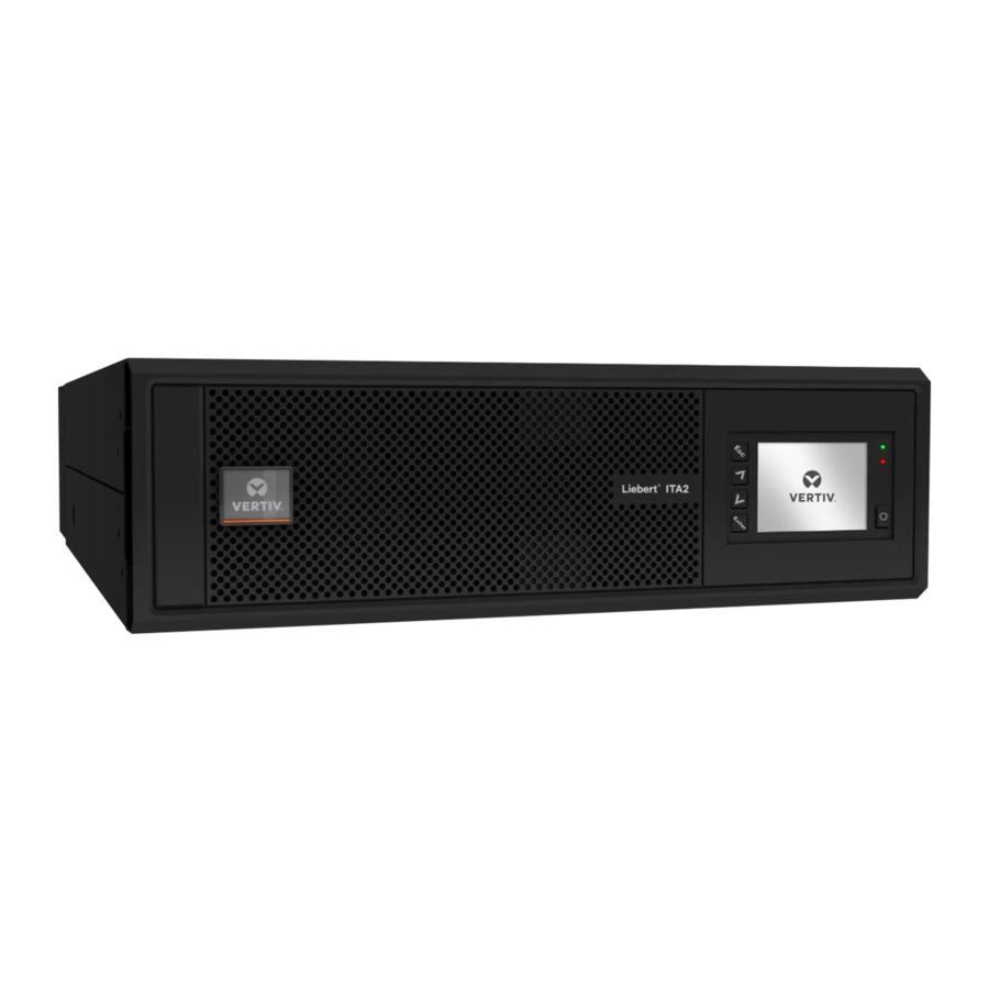
1 PRODUCT DESCRIPTION The Liebert® ITA2™ uninterruptible power system (UPS) is an intelligent, online UPS with sine wave output. The UPS offers reliable, high-quality AC power to small-scale computer centers, networks, communication systems, automatic control systems, and similar sensitive electronic equipment. 1.1 Front-panel Components The front panel of the UPS provides ventilation holes and an operation/display panel with LED indicators and function keys. -
Page 8: Rear-Panel Components
Figure 1.2 UPS Rear Panel with Terminal-block Battery Connectors Item Description Liebert® IntelliSlot™ port Dry-contact port REPO port RS-232 port Multi-function port Parallel/LBS ports Ventilation holes AC-output terminals AC-input terminals Ventilation holes Battery-input terminals USB port Vertiv | Liebert® ITA2™ Installer/User Guide... -
Page 9: Ups States And Operating Modes
Figure 1.3 UPS Rear Panel with Plug-n-Play Battery Connectors Item Description Liebert® IntelliSlot™ port Dry-contact port REPO port RS-232 port Multi-function port Parallel/LBS ports Ventilation holes AC-output terminals AC-input terminals Ventilation holes Battery-connector ports USB port 1.3 UPS States and Operating Modes NOTE: See Table 3.2 on page 42, for description of the run-indicator and alarm-indicator LEDs mentioned in this section. -
Page 10: Normal Mode
Normal operation supplies clean, conditioned, sine-wave power to connected equipment from normal utility input. The battery charger charges the batteries. On the front-panel display, the run-indicator (green) is On, the alarm indicator is OFF, and the buzzer is silent. Figure 1.4 Normal-mode Operation Vertiv | Liebert® ITA2™ Installer/User Guide... -
Page 11: Battery Mode
1.3.2 Battery Mode Battery mode supplies battery power to the load if utility power fails or if the utility voltage goes outside of the permissible range. On the front-panel display, the run indicator (green) is On, the alarm indicator (yellow) is On, and the buzzer beeps once each second. The LCD "Current" screen displays "On Battery." Figure 1.5 Battery-mode Operation Item Description... -
Page 12: Bypass Mode
(yellow) is On, and the buzzer beeps once each second. The LCD "Current" screen displays "On Bypass." Figure 1.6 Bypass-mode Operation Item Description Bypass input Maintenance-byass breaker (MBB) Bypass-input breaker (BIB) Static switch Rectifier input Rectifier-input breaker (RIB) Rectifier Battery charger Battery Inverter Automatic inverter switch Maintenance-isolation breaker (MIB) UPS output Vertiv | Liebert® ITA2™ Installer/User Guide... -
Page 13: Auto Restart Mode
If utility power fails or if its quality is out of range while the UPS is in Maintenance Bypass Mode, the UPS may shut down without notice and shut-off output power to the load. NOTE: The UPS has no user-serviceable parts. If the UPS malfunctions and requires service, visit http://www.Vertiv.com/en-us/support/ or contact your local Vertiv representative. 1 Product Description... - Page 14 This page intentionally left blank Vertiv | Liebert® ITA2™ Installer/User Guide...
-
Page 15: Installation
2 INSTALLATION Installation must be performed by properly-trained and qualified personnel. Do not start the UPS until after the installation is finished, and the system is commissioned by an authorized engineer. WARNING! Risk of electrical shock. Can cause property damage, injury, and death. The unit has several circuits that are energized with high DC and AC voltages. -
Page 16: Environment Of Installation Area
Maintain at least 8 in. (200 mm) in the front and rear of the UPS, see Figure 2.1 below. Figure 2.1 Required Clearances Item Description UPS (top view). Wall or other solid surface. Vertiv | Liebert® ITA2™ Installer/User Guide... -
Page 17: Installation Tools
2.1.3 Installation Tools IMPORTANT! All tools used to install and maintain the ITA2 UPS and equipment must be insulated. The following tools are required to properly install your UPS: • Torque wrench • Slotted screwdriver • Multimeter • #3 Phillips-head screwdriver •... - Page 18 The UPS includes an overcurrent-protection device for the battery. UPS Output The UPS includes output overcurrent protection in all modes of operation. If the customer-provided output-distribution panel is not within sight of the UPS, the distribution panel must include a main breaker. Vertiv | Liebert® ITA2™ Installer/User Guide...
-
Page 19: Equipment Handling And Unpacking
The UPS weighs approximately 50.7 lb (23 kg). During unpacking: • Inspect the UPS for damage. If you find any problem, file a damage claim with the carrier immediately and send a copy to Vertiv at: Attn: Traffic Department Vertiv Corporation 1050 Dearborn Drive P.O. - Page 20 5. Place the UPS, battery cabinets, and the MBC on the 2 support-base assemblies. Figure 2.3 Support bases Description Support bases Spacers with connectors Figure 2.4 Tower-mounted ITA2 UPS System with Battery Cabinets and MBC Vertiv | Liebert® ITA2™ Installer/User Guide...
-
Page 21: Rack Installation
2.4 Rack Installation NOTICE Risk of improper transport. Can cause damage to the UPS, MBC, or battery cabinets. Never attempt to lift or move the UPS, MBC, or battery cabinets with the rack brackets. The brackets and screws are not meant to lift the units. NOTICE Risk of improper installation. - Page 22 Figure 2.5 Guide-rail and Rack-bracket Installation Item Description Bracket screw, 4 per bracket Bracket (x2) Rail screw, 4 per rail Guide rail, 1 per side Rack-mount screw, 4 per bracket Vertiv | Liebert® ITA2™ Installer/User Guide...
-
Page 23: Connecting Power Cables
Figure 2.6 Rack-mounted ITA2 UPS System with Battery Cabinets and MBC 2.5 Connecting Power Cables WARNING! Risk of electrical shock. Can cause property damage, injury, and death. The unit has several circuits that are energized with high DC and AC voltages. Check for voltage with both AC and DC voltmeters before making contact and before working within the UPS. -
Page 24: Connecting A Single-Input Configuration
Prepare for connection by removing the conduit box cover, opening knockout holes, and routing cables through the conduit. 2. Leave the shorting busbars in place on the UPS input terminal block. Vertiv | Liebert® ITA2™ Installer/User Guide... - Page 25 3. Refer to the single-input terminal block illustrated in Figure 2.7 on the next page, and connect the cables from the upstream feeder panel: • Phase A to L1 • Phase B to L2 • Phase C to L3 • Neutral to N •...
- Page 26 A, output phase A N, output neutral pC, output phase C pB, output phase B pA, output phase A L1, input phase A L2, input phase B L3, input phase C rA, rectifier input A Vertiv | Liebert® ITA2™ Installer/User Guide...
-
Page 27: Connecting A Dual-Input Configuration
Item Description ba, bypass input A rB, rectifier input B bB, bypass input B rC, rectifier input C bC, bypass input C Battery-cable connector 2.5.2 Connecting a Dual-input Configuration WARNING! Risk of electrical shock. Can cause equipment damage, injury and death. Before beginning installation, verify that all external overcurrent protection devices are open (Off), and that they are locked-out and tagged appropriately to prevent activation during the installation. -
Page 28: Connecting A Single Battery-Cabinet System
The factory-provided, UPS-to-battery power cable, see Figure 2.8 on the facing page, connects to connector A on both battery cabinets in a single/first battery string. The battery-to-battery power cable connects additional battery strings/cabinets, see Connecting Additional Battery-cabinet systems page 32. Vertiv | Liebert® ITA2™ Installer/User Guide... - Page 29 Figure 2.8 Power Cables Item Description UPS-to-battery cable (for hard-wired configurations) Battery-to-battery cable (also UPS-to-battery for plug-and-play configurations) To connect the UPS with terminal-block connections to the battery-cabinet system: Make sure the battery breaker on the rear of the cabinet is open (Off). 2.
- Page 30 Connect the end labeled "Port B" to one of the connectors on the rear of the UPS and tighten the securing screws. • Connect the end labeled "Port A" to Connector A on the battery cabinet. 3. Repeat step 2, for the second battery cabinet. Vertiv | Liebert® ITA2™ Installer/User Guide...
- Page 31 4. Using a communication cable with RJ-45 connectors, refer to Figure 2.11 on page 30, and: • Connect one end to the multi-function port on the rear of the UPS. • Connect the other end to one of the RJ-45 communication ports on the first battery cabinet.
- Page 32 Figure 2.10 Cabling the UPS and two 3U battery strings in parallel Item Description Ground screw (PE) BAT – (negative) connector BAT N (neutral) connector BAT + (positive) connector Communication-port connector (RJ-45) Connector A Communication-port connector 1 Communication-port connector 2 Vertiv | Liebert® ITA2™ Installer/User Guide...
- Page 33 Item Description Connector B Battery cabinet 4 Battery cabinet 3 Battery string 2 Battery cabinet 2 Battery cabinet 1 Battery string 1 Communication cable, UPS to Comm Port 1 on Battery-cabinet 1 UPS-to-battery power cable, to Connector A on Battery-cabinets 1 and 2 Communication cable, Comm Port 2 to Comm Port 1 on Battery-cabinet 3 Battery-to-battery power cable, Battery-cabinet 1 Connector B to Connector A on Battery-cabinet 3 Battery-to-battery power cable, Battery-cabinet 2 Connector B to Connector A on Battery-cabinet 4...
- Page 34 Figure 2.11 Cabling the UPS and two 2U battery strings in parallel Item Description Battery-cable connectors Multi-function connector (RJ-45) Communication-port connector (RJ-45) Communication-port connector (RJ-45) Connector B Connector A DIP switch Battery cabinet 4 Battery cabinet 3 Battery string 2 Vertiv | Liebert® ITA2™ Installer/User Guide...
- Page 35 Item Description Battery cabinet 2 Battery cabinet 1 Battery string 1 Communication cable, UPS to communication port on Battery-cabinet 1 Battery cable to Connector A on battery-cabinets 1 and 2 Communication cable between communication ports on each battery cabinet. Battery cable from Connector B on battery-cabinet 1 to Connector A on battery-cabinet 3 Battery cable from Connector B on battery-cabinet 2 to Connector A on Battery-cabinet 4 2 Installation...
-
Page 36: Connecting Additional Battery-Cabinet Systems
(battery-cabinet 4). 3. Verify that the connector colors align and press the cable in firmly to fully-seat the connectors. 4. Tighten the captive screws on the extension cable to prevent the extension cable from loosening. Vertiv | Liebert® ITA2™ Installer/User Guide... - Page 37 5. Connect an RJ-45 communication cable: • On 3U strings, to Communication-port 2 on the first cabinet in the first string (battery- cabinet 1), and the other end to Communication-port 1 on the first cabinet in the additional string (battery-cabinet 3). •...
- Page 38 Figure 2.12 DIP Switch on Rear Panel of 2U Battery Cabinet Item Description Group Number Vertiv | Liebert® ITA2™ Installer/User Guide...
-
Page 39: Communication Connections
Provides dry-contact alarm information, including signals for: On Battery, On Bypass, Low Battery, Summary Alarm, Liebert® UPS Fault and On UPS for communication to a remote-monitoring system or network-connected Vertiv or third- IS-Relay Card party shut-down software. The card also accepts input signals to shut-down the UPS during any operating mode. -
Page 40: Repo Connection
If a REPO connection is not required for the UPS, the factory-installed jumper between Pin 9 and Pin 10 must remain installed for the UPS to operate. NOTE: The terminal-block wire range is 18 AWG ~ 22 AWG (0.82 mm ~ 0.33 mm ), and we recommend using 18-AWG copper, shielded, signal cable. Vertiv | Liebert® ITA2™ Installer/User Guide... -
Page 41: Dry-Contact Connections
Figure 2.13 REPO-connections Detail Item Description No REPO connection—factory-supplied jumper must remain installed. Normally-closed (N.C.) connection—remove factory-supplied jumper and wire pins 2 and 4 to a remote switch. Normally-open (N.O.) connection—factory-supplied jumper must remain installed. Port 5/REPO input. See Table 2.6 on the previous page, for the pinout details. 2.8.3 Dry-contact Connections The UPS includes 5 dry-contact ports described in Table 2.7 on the next page. -
Page 42: Connecting Usb Communication Cables
To connect the serial port communication cable, connect one end of the DB-9 serial-port communication cable to the DB-9 serial port on the rear panel of the UPS. Connect the other end to the computer’s DB-9 port. The port uses the RS-232 protocol. Vertiv | Liebert® ITA2™ Installer/User Guide... -
Page 43: Connecting Multi-Function Port (Rj-45)
The multi-function port is a standard RJ-45 connection that supports Modbus/Jbus protocol, and on units with terminal-block battery connector, it connects Vertiv temperature and temperature/humidity sensors. In addition, when connecting 2U battery cabinets, you must use this port to automatically detect the number of battery strings and for temperature-compensated charging. - Page 44 This page intentionally left blank Vertiv | Liebert® ITA2™ Installer/User Guide...
-
Page 45: Operation And Display Panel
3 OPERATION AND DISPLAY PANEL The operation/display panel includes LED indicators, function keys, and an LCD interface to configure and control UPS operation. Figure 3.1 UPS Front-panel Display Table 3.1 Display-panel Button Functions and Descriptions Button Function Description Enter Confirm or enter selection. Move to previous page, increase value, move left. -
Page 46: Led Indicators
3.2 Audible Alarm (Buzzer) An audible alarm accompanies various events during UPS operations. Table 3.3 on the facing page, describes the sounds and their meaning. To silence an alarm, see Silencing the Audible Alarm on page 53. Vertiv | Liebert® ITA2™ Installer/User Guide... -
Page 47: Lcd Menu And Screens
Table 3.3 Audible-alarm Descriptions Sound Indicates: Continuous beep Generated when a UPS fault appears, such as a fuse or hardware failure. One beep every 0.5 seconds Generated when a UPS critical alarm appears, such as on inverter overload. One beep every 1 second Generated when a UPS critical alarm appears, such as on battery low voltage. -
Page 48: Start-Up And Ups Mimic Screens
3.3.1 Start-up and UPS Mimic Screens At start-up, the UPS executes a system test and displays the Vertiv logo screen for 10 to 15 seconds, shown in Figure 3.1 on page 41. After the test completes, an overview screen shows status information, the active (green) power path, and the non-working power path (gray). - Page 49 Status Screen The status screen displays voltages, currents, frequencies, and parameters on individual tabs for input, bypass, battery, output, and load status. To view the UPS status information: At the main menu, select the Status icon, and press Enter. 2. Use the arrow buttons to move the cursor left/right and select a tab, then press Enter to display the status information for the selected tab.
- Page 50 At the main menu, select the Log icon, and press Enter. 2. Use the arrow buttons to move the cursor left/right and select a tab, then press Enter to display the log for the selected tab. Figure 3.9 Current and History Log Tabs Vertiv | Liebert® ITA2™ Installer/User Guide...
- Page 51 About Page The About screen offers tabs that list information about the product and the network. To view the product and network information: At the main menu, select the Settings icon, and press Enter. 2. Use the arrow buttons to move the cursor left/right and select a tab, then press Enter to display the information for the selected tab.
-
Page 52: Editing Display And Operation Settings
Press the up-arrow button to change the digit, then press the down-arrow button to move to the next digit. 2. Repeat to select each digit, and press Enter to submit the password. Figure 3.11 Password Prompt Vertiv | Liebert® ITA2™ Installer/User Guide... - Page 53 Table 3.5 Settings Available at the Display Panel Settings Parameter range Default setting Auto restart Disable, Enable Enable Auto restart delay 0 - 999 seconds Guaranteed Shutdown Disable, Enable Disable Remote Control Disable, Enable Enable Remote Power ON delay 0 - 999 seconds Remote Shutdown delay 0 - 999 seconds LBS Select...
- Page 54 Auto Rotate Monitor Audible Alarm Disable, Enable Enable UPS Comm Address Control Port Protocol Modbus, Sensor Sensor Modbus Address 1 – 128 Change Settings Password 0 – 9, must be six digits in length 111111 Vertiv | Liebert® ITA2™ Installer/User Guide...
-
Page 55: Changing The Password
Table 3.5 Settings Available at the Display Panel (continued) Settings Parameter range Default setting Appears only when outlet Turn outlet ON is off Appears only when outlet Turn outlet OFF is on Appears only when outlet Reboot outlet is on Turn off when UPS overload on Yes, No Outlet... -
Page 56: Selecting The Display Language
3. Use the arrow buttons to select the Monitor tab, then press Enter. 4. Use the down arrow to highlight Date or Time, then press Enter. 5. Use the up/down arrows to select the date/time, then press Enter to confirm. Vertiv | Liebert® ITA2™ Installer/User Guide... -
Page 57: Operating The Ups
4 OPERATING THE UPS 4.1 Silencing the Audible Alarm If the audible alarm is enabled, it may sound during UPS operation. To silence the alarm, press and hold the ESC button for 3 seconds. The button is located on the front-panel display, see Operation and Display Panel on page 41. -
Page 58: Transferring From Normal (Inverter) To Bypass Mode
Figure 4.3 on the facing page. a. Use the up/down arrows to select no or yes, or press the ESC to cancel. b. Press Enter to confirm the action. Figure 4.2 Turn off inv—Bypass power in normal range Vertiv | Liebert® ITA2™ Installer/User Guide... -
Page 59: Transferring From Bypass To Normal (Inverter) Mode
Figure 4.3 Output shutdown—Bypass power outside normal range 4.4 Transferring from Bypass to Normal (Inverter) Mode To transfer to the inverter (normal operation) or turn on the UPS when the UPS is on internal bypass mode: Press and hold the power button for 2 seconds. •... -
Page 60: Transferring To Maintenance-Bypass Mode
Figure 4.5 Transfer with interrupt 4.5 Transferring to Maintenance-bypass Mode The transfer procedure puts the UPS in maintenance-bypass mode for safe servicing by a Vertiv service technician. To transfer from normal operation to maintenance-bypass mode: Press and hold the power button for 2 seconds. -
Page 61: Remote Emergency Power-Off (Repo)
4. Verify that the UPS is operating in internal bypass mode before proceeding. • If the unit is not in Bypass mode, see Transferring from Normal (Inverter) to Bypass Mode on page 54, for the steps. NOTICE Risk of improper operation. Failure to have the UPS operating on internal bypass and performing the next step will result in loss of all output power to the connected equipment. - Page 62 This page intentionally left blank Vertiv | Liebert® ITA2™ Installer/User Guide...
-
Page 63: Maintenance
There are no user serviceable parts in the UPS. Attempting to service the unit yourself can void the warranty. Any routine maintenance other than cleaning, must be performed by a Vertiv service technician. Visit http://www.Vertiv.com/en-us/support/, or contact your Vertiv representative. - Page 64 Battery Safety If the battery kit is damaged in any way or shows signs of leakage, contact Vertiv technical support immediately. Handle, transport, and recycle batteries in accordance with local regulations. WARNING! Risk of electrical shock. Can cause personal injury and death. When connected together, battery-terminal voltage is potentially lethal.
- Page 65 Disposing of the waste lead-acid battery in a landfill or other waste dump can result in serious environment pollution and violates national and local laws. Vertiv has a service network and recycle system to assist in complying with laws governing waste battery disposal. Visit http://www.Vertiv.com/en-us/support/ for information about recycling the waste battery.
- Page 66 This page intentionally left blank Vertiv | Liebert® ITA2™ Installer/User Guide...
-
Page 67: Specifications
6 SPECIFICATIONS Table 6.1 Specifications Item Description 8 kVA 10 kVA Rated Voltage 208/220VAC, 3 Phase, 4W+Gnd Voltage Range, VAC 96 ~ 144 Input Rated Frequency Hz 3 Phase 4W+Gnd Frequency Range, Hz 40 ~ 70 Power Factor ≥0.99, at full load; ≥0.98, at half load Rated Power 8 kVA/7.2kW 10kVA/10kW... - Page 68 Guide rail for rack installation; supplied with UPS; includes one left and one right Rack-Mounting Kit ITA2-RMKIT guide rail and mounting hardware. The rails will support 150 lb (68 kg). The kit is compatible with various server cabinets, UPS’s, battery cabinets and POD’s. Vertiv | Liebert® ITA2™ Installer/User Guide...
-
Page 69: Standard Battery Back-Up Time With A Single Ups
Table 6.2 Options (continued) Option Model Description Communication Options IS-RELAY Liebert IntelliSlot Relay Card IS-UNITY-DP Liebert IntelliSlot Unity card for network communication Ambient Temperature Sensor IRM-S01T Ambient Temperature Sensor ITA2- 3 ft. (1m) PARACBL1M ITA2- Parallel Communication Cable 9.8 ft. (3m) PARACBL3M (An N + 1 communication cable is required for each UPS... - Page 70 Table 6.4 Back-up Time for 10-kVA/10-kW Models in Minutes Load Level Number 100% Battery Strings 10 kW 9 kW 8 kW 7.5 kW 7 kW 6 kW 5 kW 4 kW 3 kW 2.5 kW 2k W 1 kW Vertiv | Liebert® ITA2™ Installer/User Guide...
-
Page 71: Appendices
APPENDICES Appendix A: UPS Prompts and Alarms A.1 Prompt Window A prompt window is displayed during the operation of the system to alert you to certain conditions and/or to require confirmation of a command or other operation. Table A.1 UPS Prompts Prompt Description System setting is different, please... - Page 72 The bypass input voltage or frequency exceeds normal Bypass abnormal Check the upstream bypass input breaker(s) to operating range; the UPS is operating in online or battery in ECO mode ensure they are closed mode Vertiv | Liebert® ITA2™ Installer/User Guide...
- Page 73 Auto, BypDisa or 50 Hz, None required or change setting to Auto, BypEna BypDisa or 60 Hz, BypDisa Check UPS display for other alarms or Contact Vertiv Bypass mode The UPS is operating on bypass power...
- Page 74 Remove all loads, restart the UPS, then turn loads on Output short An output short circuit has been detected one at a time to locate the failed equipment Rectifier fault A failure of the rectifier has been detected Contact VertivTechnical Support Vertiv | Liebert® ITA2™ Installer/User Guide...
- Page 75 Internal temperatures have exceeded threshold settings Verify the ventilation openings are not block or overtemp and the UPS has shutdown Contact Vertiv Technical Support The UPS model identification is not correct for the System fault Contact VertivTechnical Support firmware in the unit...
- Page 76 This page intentionally left blank Vertiv | Liebert® ITA2™ Installer/User Guide...
- Page 77 Vertiv | Liebert® ITA2™ Installer/User Guide...
- Page 78 Vertiv.com | Vertiv Headquarters, 1050 Dearborn Drive, Columbus, OH, 43085, USA © 2019 Vertiv Group Corp. All rights reserved. Vertiv and the Vertiv logo are trademarks or registered trademarks of Vertiv Group Corp. All other names and logos referred to are trade names, trademarks or registered trademarks of their respective owners. While every precaution has been taken to ensure accuracy and completeness herein, Vertiv Group Corp.
Need help?
Do you have a question about the Liebert ITA2 and is the answer not in the manual?
Questions and answers