Table of Contents
Advertisement
Advertisement
Table of Contents

Subscribe to Our Youtube Channel
Related Manuals for Vertiv Liebert ITA2 30kVA


Summary of Contents for Vertiv Liebert ITA2 30kVA
- Page 1 Liebert® ITA2 30kVA User Manual...
- Page 3 The purchased products, services, and features are stipulated by the contract made between Vertiv Co., and the customer. All or part of the products, services, and features described in this document may not be within the purchasing scope or the usage scope.
- Page 4 Purpose of the Document This document applies to the Liebert® ITA2 UPS which is the next generation series of UPS that provides continuous, high quality AC Power to business critical equipment. This document explains the product description, installation measures, operational workflow, and thorough aspects from the user perspective.
- Page 5 Version Information Date Revision Change 11.01.19 V1.0 Initial release. 09.08.19 V1.1 Update some contents in Chapters 2, 3 and 8. 24.05.19 V1.2 Update Sections 5.2.4 and 5.3.
- Page 6 Near heat sources or strong electromagnetic interferences Disclaimer Vertiv disclaims any and all responsibility or liability for the defects or malfunction caused by: Application range or operating environment outside the specifications Unauthorized modification, improper installation or operation ...
- Page 7 Therefore, the installation and operation personnel must receive strict training and master the correct operations and all the safety points before operation. When operating Vertiv products, the operation personnel must observe the safety rules in the industry, the general safety points and special safety instructions provided by Vertiv.
- Page 8 1. Before moving or rewiring the UPS, disconnect mains input power and the battery and make sure that the UPS is completely shut down. Otherwise, the output terminal may carry live voltage, presenting an electric shock hazard 2. Liquid or other irrelevant external objects are prohibited inside the UPS. 3.
- Page 9 Battery high voltage 1. All the physical service and maintenance of the battery are performed by the trained technicians. 2. Operation on the battery will result in electric shock and high short-circuit current, therefore, before operating the battery, the following should be observed: Remove the watches, rings and other metal objects.
- Page 10 The Manual Describes The Following Devices Product Model 30kVA ITA-30k00AL3302P00 (Long back-up model) VIII...
-
Page 11: Table Of Contents
Table of Contents 1 Product Introduction ..............................1 1.1 Features ....................................1 1.2 Model Configurations ................................. 2 1.3 Appearance And Components ............................2 1.3.1 Appearance ................................2 1.3.2 Components ................................3 1.4 Operating Principle ................................4 1.5 UPS State And Operation Mode ............................5 1.5.1 Normal Mode ................................ - Page 12 2.7.3 Normal Mode Start-Up ........................ 28 2.7.4 Battery Mode Start-Up ....................... 30 3 Parallel UPS Installation And Commissioning ....................31 3.1 Features ..............................31 3.2 Requirements ............................31 3.3 Mechanical Installation .......................... 32 3.4 Connecting Power Cables ........................32 3.4.1 Connecting I/O Cables ........................ 33 3.4.2 Connecting Parallel Cables ......................
- Page 13 5 UPS Operation Instructions ............................ 62 5.1 UPS Start-Up............................62 5.2 Transfer Procedures Between Operation Modes .................. 62 5.2.1 Transfer From Normal Mode To Battery Mode ................62 5.2.2 Transfer From Inverter Mode To Bypass Mode ................. 63 5.2.3 Transfer From Bypass Mode To Inverter Mode ................. 64 5.2.4 Transfer From Inverter Mode To Maintenance Bypass Mode ...........
- Page 14 8.6 Communication Options And Temperature/Humidity Sensor ............. 87 Appendix 1 LCD Parameters Setting ........................89 Appendix 2 Glossary ..............................91 Appendix 3 Hazardous Substances And Content ..................... 92...
-
Page 15: Product Introduction
Liebert® ITA2 30kVA UPS (UPS for short) is an intelligent online UPS system with sine wave output developed by Vertiv. The UPS offers reliable and high quality AC power to the precision instrument. The rack/tower installation can be used depending on your requirements. It is applicable to supplying AC power to small scale computer center, network, communication system, automatic control system and precision instrument. -
Page 16: Model Configurations
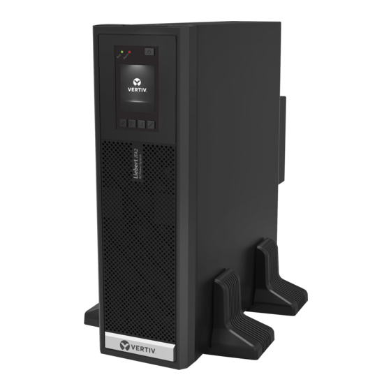
Output Remark Common input configuration (default), 30kVA Three phase Three phase split bypass configuration 1.3 Appearance And Components 1.3.1 Appearance The UPS appearance is shown in Figure 1-1. Figure 1-1 Appearance of UPS Vertiv I Liebert ITA2 30kVA I Manual... -
Page 17: Components
6. AC output port 7. REPO port 8. USB port 9. Multifunction port 10. Battery input port 11. AC input port Figure 1-3 UPS rear panel Non-authorized personnel are prohibited from opening the UPS chassis cover. Vertiv I Liebert ITA2 30kVA I Manual... -
Page 18: Operating Principle
4. After the input mains returns within tolerance levels, the UPS will automatically transfer from Battery mode to Normal mode, the mains supplies DC power to the inverter through the rectifier/PFC circuit, and then the electronic transfer switch supplies AC power to the load. Vertiv I Liebert ITA2 30kVA I Manual... -
Page 19: Ups State And Operation Mode
In Normal mode, the run indicator (green) is on, the alarm indicator is off, and the buzzer is silence. Static switch Bypass input Rectifier/PFC Inverter Mains input UPS output Charger Battery Figure 1-5 Normal mode Vertiv I Liebert ITA2 30kVA I Manual... -
Page 20: Bypass Mode
Mains input UPS output Charger Battery Figure 1-6 Bypass mode In case of mains failure or mains voltage out of range in Bypass mode, the UPS will shut down and stop the output Vertiv I Liebert ITA2 30kVA I Manual... -
Page 21: Battery Mode
UPS will not transfer to Normal mode, but shut down the bypass. 2. In ECO mode, the efficiency of the UPS is up to 99%. Vertiv I Liebert ITA2 30kVA I Manual... -
Page 22: Fault State
Battery Figure 1-8 Maintenance bypass mode In the event of UPS malfunctions or abnormal operation, contact your nearest Vertiv branch office or local service center. NEVER attempt to repair the UPS yourself, as this may result in injury to personnel and/or damage to equipment. -
Page 23: Specifications
Inverter ←→ Bypass Asynchronous transfer (default): ≤20ms Or 40ms, 60ms, 80ms, 100ms and 200ms are available Noise < 60dB Panel display mode Colorful LCD Safety IEC/EN62040-1 Conduction emission IEC/EN62040-2 Harmonic current IEC/EN61000-3-12 Vertiv I Liebert ITA2 30kVA I Manual... - Page 24 -40°C ~ +70°C (battery excluded); -25°C ~ +55°C (battery included) condition Relative humidity 5%RH ~ 95%RH, non-condensing Altitude ≤3000m; derating when higher than 3000m Size W*D*H (mm) 430*570*130 Net weight (kg) 23.5 Weight Gross weight (kg) Vertiv I Liebert ITA2 30kVA I Manual...
-
Page 25: Single Ups Installation And Commissioning
1. Remove the side panels and top cover. Use a hammer or straight screwdriver to straighten the connection hook that connects the side panels to the top cover, as shown in Figure 2-1. Figure 2-1 Straightening the hook Vertiv I Liebert ITA2 30kVA I Manual... -
Page 26: Ups Moving
The battery is very heavy. Please use proper method to move and lift the battery, so to prevent any damage to human being or the battery terminal. Severe damage to the battery may cause fire. Vertiv I Liebert ITA2 30kVA I Manual... -
Page 27: Installation Preparation
If necessary, an indoor exhaust fan should be installed to keep the indoor temperature from rising. An air filter should be used in a dusty environment where the UPS is to be operated. Vertiv I Liebert ITA2 30kVA I Manual... - Page 28 When the UPS uses an external battery, you must install a battery protective device (such as fuse or circuit breaker) close to the battery, and use the shortest wiring distance for the connection between the protective device and the battery. Vertiv I Liebert ITA2 30kVA I Manual...
-
Page 29: Installation Tools
Electric hand drill Adjustable wrench Slotted screwdriver Cross head screwdriver Stepladder Forklift Drill Wire cutting plier Claw hammer Diagonal cutting plier Insulating shoes Antistatic gloves Electrician knife Cable tie Insulating tape Insulating gloves Vertiv I Liebert ITA2 30kVA I Manual... -
Page 30: External Protective Devices
The earth leakage current fed by the RFI filter in the UPS, ranges from 3.5-100 mA. Since earth leakage current is high which can cause false tripping of the circuit breaker. Therefore, we do not recommend to use the MCB with leakage current protection at upstream. Vertiv I Liebert ITA2 30kVA I Manual... -
Page 31: Battery Input
(accessory) together through the fastenings, as shown in Figure 2-4, and place them onto the flat installation table. Fastening Support base Support base extension Support base Figure 2-4 Connecting the support base with support base extension Vertiv I Liebert ITA2 30kVA I Manual... -
Page 32: Rack Installation
1. Use eight M4 × 10 screws to fix two brackets (accessories) respectively on both sides of the UPS front panel, as shown in Figure 2-6. Screw (8pcs) Bracket (2pcs) Figure 2-6 Installing brackets It is prohibited to move the UPS through the brackets. Vertiv I Liebert ITA2 30kVA I Manual... - Page 33 Align the installation holes of the guide rail with the square holes of the rack, fix the guide rail onto the rack through the guide rail screws (totally eight), each left guide rail and right guide rail need four guide rail screws, as shown in Figure 2-9. Vertiv I Liebert ITA2 30kVA I Manual...
- Page 34 3. Place the UPS on the guide rails in the rack, and push it completely into the rack. Use four M6 × 16 screws to fix the UPS in the rack through the brackets, as shown in Figure 2-11. Guide rail Rack Bracket Screw (4pcs) Figure 2-11 Installing the UPS Vertiv I Liebert ITA2 30kVA I Manual...
-
Page 35: Connecting Power Cables
UPS. The specified upstream breakers below are required to obtain the conditional short-circuit current rating, Icc at 10kA symmetrical rms. The specified upstream breakers should comply with an IEC 60947 series standard. Vertiv I Liebert ITA2 30kVA I Manual... -
Page 36: Connecting I/O Cables
Figure 2-12 Terminals layout of the I/O terminal block After the power cables connection, the protective cover board of the I/O terminal block must be reinstalled so as to avoid electric shock. Vertiv I Liebert ITA2 30kVA I Manual... - Page 37 BAT+, BAT N, BAT- and PE, then fasten the fixing screws. Figure 2-13 Wiring diagram (3-in 3-out, common input configuration) Vertiv I Liebert ITA2 30kVA I Manual...
-
Page 38: Connecting Battery Cables
2. When multiple batteries are used, they shall be connected in series and then in parallel. Before loading and power-up, it must be detected that the total voltage of the batteries is as Vertiv I Liebert ITA2 30kVA I Manual... - Page 39 Installation steps are as follows: Batter insulationg plate Figure 2-15 Installing battery insulating plates 1. First crimp the user external cable on the battery terminals, Figure 2-15 shows the OT terminals. Vertiv I Liebert ITA2 30kVA I Manual...
- Page 40 5. Batteries of different types, names or newness shall not be used together. Otherwise, the battery inconsistency will cause frequent over-discharge or under-charge of certain battery. At last, the battery will have premature failure, and the entire string of battery will have insufficient backup time Vertiv I Liebert ITA2 30kVA I Manual...
-
Page 41: Single Ups Commissioning
4. The output terminals of the UPS and the POD (if configured) are energized upon the startup. If the load is connected with the output terminals, make sure that the power to the load is safe. Vertiv I Liebert ITA2 30kVA I Manual... -
Page 42: Start-Up Interface
3. Finish and check the parameter settings of the single UPS. a) At main menu screen, press the key to select 'Settings', and press the to enter the interface shown in Figure 2-18. Settings Control Status About Maintain Figure 2-18 Main menu screen Vertiv I Liebert ITA2 30kVA I Manual... - Page 43 5. Measure whether the inverter output voltage is normal. 6. If the battery is not connected, the alarm indicator is yellow. If the battery is connected, the alarm indicator turns off. Vertiv I Liebert ITA2 30kVA I Manual...
-
Page 44: Battery Mode Start-Up
2. Press the power button for two seconds, the LCD prompts a dialogue box shown in Figure 2-21. Confirm Settings Control Status Turn on UPS? About Maintain Figure 2-21 Turning on UPS After selecting 'YES', the inverter starts, and the run indicator (green) is on. Vertiv I Liebert ITA2 30kVA I Manual... -
Page 45: Parallel Ups Installation And Commissioning
Refer to 'Warning: high leakage current' of Safety Precautions before Contents. 4. The outputs of all single UPSs must be connected to the same output bus. Vertiv I Liebert ITA2 30kVA I Manual... -
Page 46: Mechanical Installation
Parallel 3-in 3-out Single input cable for Single output cable Total neutral line for Grounding cable for number parallel system for parallel system parallel system parallel system 2 units 3 units 4 units Vertiv I Liebert ITA2 30kVA I Manual... -
Page 47: Connecting I/O Cables
Configure each UPS with extenal input MCB and extenal output MCB when carring out the power distribution for the parallel system, as shown in Figure 3-2. After connecting power cables, the protective cover of the I/O terminal block must be reinstalled to avoid electric shock. Vertiv I Liebert ITA2 30kVA I Manual... -
Page 48: Connecting Parallel Cables
UPS4 Figure 3-3 Cable connection schematic diagram of 3 + 1 parallel system 1. The Vertiv parallel cables must be used for the parallel system. 2. If the parallel communication fault occurs during the parallel commissioning or operation, just shut off the system and check whether the connection of the parallel cables are correct. -
Page 49: Connecting Battery Cables
Refer to 2.6 Connecting Power Cables to configure an MCB. Ensure that the LCD settings are correct when using the battery strings independently for the parallel system, refer to 3.5.2 Parallel System Parameters Settings for details. Vertiv I Liebert ITA2 30kVA I Manual... - Page 50 1. To ensure the abundant backup time of the battery, it is recommended to use the external battery cabinet with larger capacity. 2. The UPS shares the battery system, make sure that in each of the UPS enable common battery function. Refer to 3.6.5 Settings Parameter of LBS. Vertiv I Liebert ITA2 30kVA I Manual...
- Page 51 MCB, as shown in Figure 3-5. UPS 2 UPS 1 UPS1 MCB UPS2 MCB - PE - PE Negative battery strings Positive battery strings Figure 3-5 Connection diagram of shared battery string in 1 + 1 parallel system Vertiv I Liebert ITA2 30kVA I Manual...
-
Page 52: Commissioning Parallel System
The output terminals of the UPS and the POD (if configured) will be live upon start-up. When bypass of the single UPS in the parallel system is not consistent, the system fault may occur, check and confirm the bypass before power-on. Vertiv I Liebert ITA2 30kVA I Manual... -
Page 53: Parallel System Parameters Setting
Refer to 3.5.2 Parallel System Parameters Setting for the parallel parameters setting for each UPS. Note whether there is an alarm of 'Parallel comm. Fail', if yes, clear the fault according to Table 4-5. Carry out the following procedures if the UPS is running normally. Vertiv I Liebert ITA2 30kVA I Manual... - Page 54 Check and confirm that the power distribution mode, each power cable and signal cable of the added UPS are well connected without short circuit. Check that the battery installation and cables connection are correct without short circuit, and that the positive and negative are correct. Vertiv I Liebert ITA2 30kVA I Manual...
-
Page 55: Installation And Commissioning For Dual Bus System
The operation mode of the dual bus system contains master system and/or slave system running in Normal mode or Bypass mode. The schematic diagram of the LBS system built by two UPSs is shown in Figure 3-8. Vertiv I Liebert ITA2 30kVA I Manual... -
Page 56: Installing External Protective Device
If the input terminal has leakage current, the leakage current protective device should be installed before the input terminal. Vertiv I Liebert ITA2 30kVA I Manual... -
Page 57: Connecting Lbs Cables
There are three items of LBS for selection: Disable, Slave, Master. Monitor System LBS select Disable IT system compatibility Disable Dry connect 1 (Input) Maintain... Dry connect 2 (Output) Low battery Figure 3-10 LBS parameters setting interface Vertiv I Liebert ITA2 30kVA I Manual... - Page 58 Through the above to realize the inverter voltage phase synchronization of two sets of UPS system, and realize the reliable transfer between the two sets of UPS output voltage and STS, then provide the reliable uninterrupted power supply to the load. Vertiv I Liebert ITA2 30kVA I Manual...
-
Page 59: Operation And Display Panel
4. Alarm indicator 5. Power button Figure 4-1 Operation and display panel The device has a gravity sensor function, thus the LCD display direction will be changed according to the device layout mode. Vertiv I Liebert ITA2 30kVA I Manual... -
Page 60: Led Indicators
Used to page up, turn left or add value, etc. Down Used to page down, turn right or reduce value, etc. Escape Used to back, escape, cancel or forbid operation Power Used to power on, power off or transfer to Byapss mode Vertiv I Liebert ITA2 30kVA I Manual... -
Page 61: Initial Start-Up Guidance
UPS. Start Up Guidance(1/5) Thanks for using Vertiv UPS! Press Enter to start Next Figure 4-3 Initial start-up guidance (1) Welcome page Click Next to start the guidance. Vertiv I Liebert ITA2 30kVA I Manual... - Page 62 Figure 4-5 Initial start-up guidance (3) Output page As shown in Figure 4-6, you can set output voltage, output frequency. Start UP Guidance(4/5) Output voltage 230V Output frequen... Auto,Bupass e... Prev Next Figure 4-6 Initial start-up guidance (4) Vertiv I Liebert ITA2 30kVA I Manual...
-
Page 63: Lcd Menu Structure
After the start-up, the user can operate the UPS normally, Start UP Guidance(5/5) Configuration finished Please ENTER to start Figure 4-7 Initial start-up guidance (5) 4.2 LCD Menu Structure Figure 4-8 LCD menu structure Vertiv I Liebert ITA2 30kVA I Manual... -
Page 64: Lcd Screen Types
The working modes with color display while the invalid modes with gray display. Figure 4-10 Flow screen At the flow page, press the key to enter the primary screen. Vertiv I Liebert ITA2 30kVA I Manual... -
Page 65: Main Menu Screen
After entering the submenu screen, if there is no tab control, then the cursor will stop at a certain Item. Press the key to back to the previous screen. For details about the submenu screen, see following pages. Vertiv I Liebert ITA2 30kVA I Manual... - Page 66 See below: Input Bypass Battery Output L-N voltage(V) 242.8 244.1 243.2 L-N current(A) Settings Control Status Frequency(Hz) 59.98 59.98 59.98 L-L voltage(V) 420.4 422.7 421.5 0.60 0.60 0.60 Power factor Energy(kWh) About Maintain Vertiv I Liebert ITA2 30kVA I Manual...
- Page 67 Battery Parallel Battery series Voltage selection 220V Dischg protrct time Frequency selection Auto,Bypa... 4320 min Run mode Normal Equal charge enable Redundant Temp compensation Disable System parallel num Replace battery Sync parallel parameters Vertiv I Liebert ITA2 30kVA I Manual...
- Page 68 The Control page contains the Turn ON/OFF/to BYPASS, and Manual battery test, etc.. See below: Turn on/off/to bypass Mute/Unmute audible alarm Start/Stop battery manual test Settings Control Status Clear faults Power on time 2000-01-01 00:00:00 power off time 2000-01-01 00:00:00 About Maintain Vertiv I Liebert ITA2 30kVA I Manual...
- Page 69 NA03 2016-10-01 00:00:00 02 No battery ND03 2016-10-01 00:00:00 03 Bypass abnormal NC00 2016-10-01 00:00:00 About page The About page contains the Product, Network, and Efficiency. See below: Status Settings Control About Maintain Vertiv I Liebert ITA2 30kVA I Manual...
-
Page 70: Default Screen
Maintain page The Maintain page needs correct password and for Vertiv service engineer operation only. Input Password for maintain Settings Control Status Settings Control Status **** About Maintain About Maintain 4.3.5 Default Screen During the UPS operation, if there is no alarm within two minutes, the default screen shown in Figure 4-12 will appear. -
Page 71: Prompt Window
Bypass backfeed Battery mode. The bypass relay is shorted or the SCR is damaged Output off, voltage When there is no output, the system detects that the output has a voltage is not zero Vertiv I Liebert ITA2 30kVA I Manual... - Page 72 The system can automatically start after overtemperature fault is solved. System overtemp If overtemperature, please check: 1. Ambient temperature too high or not 2. Dust is blocked or not 3. Fan fault or not Vertiv I Liebert ITA2 30kVA I Manual...
- Page 73 REPO Shutdown caused by the REPO terminal Normally Closed contact open Bypass phase During parallel connection, the bypass phase sequence is not the same. Check the reversed parallel bypass cables connection Vertiv I Liebert ITA2 30kVA I Manual...
- Page 74 Setting page is the same as the actual online number, and that abnormal the parallel cables are normal In Settings->Output->Frequency selection, 'Auto, BypDisa; 50Hz, BypDisa; 60Hz, BypDisa' Bypass disabled is set, the LCD will generate BypDisa alarm Vertiv I Liebert ITA2 30kVA I Manual...
- Page 75 The alarm occurs when model identification is incorrect. Solution: Contact service System fault manager If the alarm is caused through setting the software value by Vertiv authorized engineer, and when you wish to change the setting values, please get in touch with the Vertiv local customer service center.
-
Page 76: Ups Operation Instructions
In case of mains failure, the UPS will transfer to Battery mode. If you wish to transfer the UPS from Battery mode to Normal mode, wait few seconds for mains input recovery. After about Ten seconds, the rectifier will automatically restarts and the inverter restores the power. Vertiv I Liebert ITA2 30kVA I Manual... -
Page 77: Transfer From Inverter Mode To Bypass Mode
Status Settings Control Settings Control Status To the Bypass To the Bypass? Turn off UPS About Maintain About Maintain Confirm Settings Control Status Turn off UPS? About Maintain Figure 5-2 Bypass normal interface Vertiv I Liebert ITA2 30kVA I Manual... -
Page 78: Transfer From Bypass Mode To Inverter Mode
Settings Control Status Status Turn on UPS? To the Bypass Turn off UPS About Maintain About Maintain Confirm Settings Control Status Turn off UPS? About Maintain Figure 5-4 ECO mode not turned on Vertiv I Liebert ITA2 30kVA I Manual... -
Page 79: Transfer From Inverter Mode To Maintenance Bypass Mode
Otherwise, it may result in the load power interruption for a while. 2. To perform this function, user should select either a single POD or configure the MCB in maintenance bypass. Vertiv I Liebert ITA2 30kVA I Manual... - Page 80 5. Open the input MCB, maintenance bypass MCB and output MCB on the front panel of the POD. Perform the maintenance operation after the UPS complete shutdown. Dry contact port 4 can achieve the same function as dry contact port 3 via the above steps. Vertiv I Liebert ITA2 30kVA I Manual...
-
Page 81: Transfer From Maintenance Bypass Mode To Inverter Mode
MCB, maintenance bypass MCB and output MCB to shut down the UPS completely. For the system has been transferred to maintenance bypass system, just open the maintenance bypass MCB directly, as shown in Figure 5-9. Vertiv I Liebert ITA2 30kVA I Manual... -
Page 82: Repo
After the Auto Restart is delayed (default: 0s). During the Auto Restart delay, the UPS will charge the battery to provide a safety margin for equipment shutdown if input power fails again. Vertiv I Liebert ITA2 30kVA I Manual... -
Page 83: Language Selection
'Monitor', see Figure 5-11. System Output Battery Monitor Language English Date 2000-01-01 Time 03:52:41 Audible alarm Enable Card slot protocol YDN23 UPS Comm Address Control port protocol Sensor Figure 5-11 Monitor interface Vertiv I Liebert ITA2 30kVA I Manual... - Page 84 At this time, the LCD contents will be the language selected by you. See Figure 5-13. Figure 5-13 Changing Language 5. Press the key for several times to back to the main menu screen. Vertiv I Liebert ITA2 30kVA I Manual...
-
Page 85: Changing Current Date And Time
Enable Audible alarm Enable YDN23 Card slot protocol YDN23 Card slot protocol UPS Comm. Address UPS Comm. Address Control port protocol Sensor Control port protocol Sensor Figure 5-16 Selection of date and time Vertiv I Liebert ITA2 30kVA I Manual... -
Page 86: Setting Password
Status About Maintain Figure 5-18 Main menu 2. Press the key, the interface shown in Figure 5-19 will appear. Input Password for maintain Settings Control Status **** About Maintain Figure 5-19 Inputting password Vertiv I Liebert ITA2 30kVA I Manual... - Page 87 Figure 5-22 will appear. Monitor System Input IPv4 address 192.168.1.10 Subnet mask 255.255.255.0 Password for settings Gateway address 192.168.1.1 **** Change settings password Figure 5-22 Password for settings Vertiv I Liebert ITA2 30kVA I Manual...
- Page 88 Figure 5-25 Password changed OK 7. Press the key for several times to back to the main menu screen. Only through the correct password (default: 111111) verification can you conduct the parameters of the UPS. Vertiv I Liebert ITA2 30kVA I Manual...
-
Page 89: Communication
(STS), sever power management system (SPM), and so on) produced by Vertiv have network communication capability. The SIC card can also be used with the Network Shutdown designed by Vertiv to provide safe automatic shutdown function for the computer, in which the Network Shutdown has been installed, to protect data and reduce loss. - Page 90 The RDU-SIC card is a network management card. It can make the intelligent equipment (such as UPS, PDU and so on) developed by Vertiv have the capacity of network communication. The SIC card can also connect to the environment monitoring equipment, including IRM series or 1-Wire series temperature sensor, temperature &...
-
Page 91: Connection Cables For Dry Contact Port
Default: Maintain mode, can be set via mode shutdown (Remote the LCD settings page. When Pin 5 and Input port 1 Comms Shutdown)/ Maintain Pin 6 are shorted, the function is valid mode Vertiv I Liebert ITA2 30kVA I Manual... - Page 92 '12' connection terminals of the REPO port, and press down the terminals. The REPO cable is complete. Ensure that the REPO cable is firmly connected to avoid no action or wrong action of the REPO caused by accidental dropping or infirm contact. Vertiv I Liebert ITA2 30kVA I Manual...
-
Page 93: Connecting Usb Communication Cables
The control port adopts the standard RJ45 port, which supports the Modbus/Jbus port and connects the Vertiv temperature/temperature & humidity sensor. The user can select Modbus/Jbus protocol function or sensor function via the 'Settings' on the LCD. Vertiv I Liebert ITA2 30kVA I Manual... -
Page 94: Connecting Built-In Ethernet Port
To obtain the best user experience, it is recommended to use the Internet Explorer (IE9 or above), or the Chrome, FireFox (latest version required) Screen resolution The display with resolution of 1024*768 or above is recommended. Vertiv I Liebert ITA2 30kVA I Manual... -
Page 95: Maintenance
Charge the battery for at least 12 hours, if the battery hasn't been charged for three months at specified ambient temperature, or two months at high ambient temperature Vertiv I Liebert ITA2 30kVA I Manual... -
Page 96: Cleaning Ups
Vertiv or the nearest service center for the detailed information of the recycle system about the waste battery. Vertiv is not liable for the environment results caused by failure to comply with the notices in this section or to use the waste battery recycle system provided by Vertiv. -
Page 97: Checking Ups Functions
1. Press the power button to check if the buzzer beeps, indicators are ON and the LCD display is normal. 2. Press the ESC key to check again if the indicators are ON, the LCD display is normal and the UPS has been transferred to the inverter mode. Vertiv I Liebert ITA2 30kVA I Manual... -
Page 98: Options
POD rear panel. The front panel and rear panel of the single POD are shown in Figure 8-1. The front panel and rear panel of the 1 + 1 parallel POD are shown in Figure 8-2. Vertiv I Liebert ITA2 30kVA I Manual... - Page 99 UPS2 输入 /UPS2 INPUT UPS2 output terminals UPS2 input terminals Rear panel of the 1 + 1 parallel POD Figure 8-2 Front panel and rear panel of the 1 + 1 parallel POD Vertiv I Liebert ITA2 30kVA I Manual...
-
Page 100: Communication Cables
50kg. Use the guide rail in the rack T1832 installation installation. It is applicable to the various server cabinet, UPS, and POD For the rack mode installation procedure, refer to 2.5.2 Rack Installation. Vertiv I Liebert ITA2 30kVA I Manual... -
Page 101: Dual Bus Parts
Unity card adopts Ethernet network to monitor and manage various operating parameters, alarms and notifications about power, UNITY card IS-UNTIY-DP distribution and cooling equipment. The card also communicates with the building management system and the network management system Vertiv I Liebert ITA2 30kVA I Manual... - Page 102 COM1 port of the SIC card, and set DIP switch of the temperature sensor to '1'. For the installation and setting of the SIC card, refer to RDU-SIC Card User Manual. Vertiv I Liebert ITA2 30kVA I Manual...
-
Page 103: Appendix 1 Lcd Parameters Setting
Shared battery Disable, Enable Disable Local/Parallel battery total 7~3000Ah 18Ah Battery Low battery time 2~30 (min) Disable, 8 weeks, 12 weeks, 16 Battery test interval Disable weeks , 20 weeks , 26 weeks Vertiv I Liebert ITA2 30kVA I Manual... - Page 104 ( 'd' is a decimal number) Gateway address 192.168.1.1 SNMP NMS address 192.168.1.100 The password is numeric only Change settings password and can be set from 0 to 9. The 111111 password length is 6 Vertiv I Liebert ITA2 30kVA I Manual...
-
Page 105: Appendix 2 Glossary
Network management system Protective earth RCCB Residual current circuit breaker Residual current detector REPO Remote emergency power off Radio frequency interference Silicon-controlled rectifier SNMP Simple network monitoring protocol Static transfer switch Uninterruptible power system Vertiv I Liebert ITA2 30kVA I Manual... -
Page 106: Appendix 3 Hazardous Substances And Content
×: Means the content of the hazardous sustances in at least one of the average quality materilals of the parts is outsides the limits specified in GB/T 26572 Applicable scope: Liebert ® ITA2 30kVA UPS Vertiv I Liebert ITA2 30kVA I Manual... - Page 108 Vertiv.com | Asia-Pacific © 2019 Vertiv Co. All rights reserved. Vertiv and the Vertiv logo are trademarks or registered trademarks of Vertiv Co. All other names and logos referred to are trade names, trademarks or registered trademarks of their respective owners. While every precaution has been taken to ensure accuracy and completeness herein, Vertiv Co.
Need help?
Do you have a question about the Liebert ITA2 30kVA and is the answer not in the manual?
Questions and answers