Vertiv Liebert ITA2 User Manual
Hide thumbs
Also See for Liebert ITA2:
- User manual (140 pages) ,
- Installer/user manual (82 pages) ,
- Quick start manual (25 pages)
Table of Contents
Advertisement
Advertisement
Table of Contents

Subscribe to Our Youtube Channel
Related Manuals for Vertiv Liebert ITA2


Summary of Contents for Vertiv Liebert ITA2
- Page 1 Vertiv™ Liebert® ITA2 1-3 kVA User Manual...
- Page 2 The information contained in this document is subject to change without notice and may not be suitable for all applications. While every precaution has been taken to ensure the accuracy and completeness of this document, Vertiv assumes no responsibility and disclaims all liability for damages resulting from use of this information or for any errors or omissions.
-
Page 3: Table Of Contents
Vertiv™ Liebert® ITA2 1-3 kVA User Manual TABLE OF CONTENTS 1 Important Safety Instructions 2 Special Declaration 3 Product Introduction 3.1 Product Features 3.2 Model Configurations 3.3 Product Appearance and Components 3.3.1 Product Appearance 3.3.2 Product Components 3.4 Operating Principal 3.5 UPS State and Operation Mode... - Page 4 Vertiv™ Liebert® ITA2 1-3 kVA User Manual 5.1 UPS Start-Up 5.2 Initial Start-up Guidance 5.3 Transfer Procedures Between Operation Modes 5.3.1 Transfer from Normal Mode to Battery Mode 5.3.2 Transfer from Inverter Mode to Bypass Mode 5.3.3 Transfer from Bypass Mode to Inverter Mode 5.4 UPS Complete Shutdown...
- Page 5 Vertiv™ Liebert® ITA2 1-3 kVA User Manual 8.5 Checking UPS State 8.6 Checking UPS Functions 9 Options 9.1 Option List 10 Technical Specifications 11 Appendices Appendix A: LCD Parameters Setting Appendix B: Glossary...
- Page 6 Vertiv™ Liebert® ITA2 1-3 kVA User Manual This page intentionally left blank...
-
Page 7: Important Safety Instructions
Info. Purpose of the Document This document applies to Vertiv™ Liebert® ITA2 1-3 kVA UPS and cooling solutions which maintain optimal environmental control of technological ecosystems at minimal operating costs. This document gives an overview of the specifications, installation, commissioning, and maintenance procedures with troubleshooting from the user's perspective. - Page 8 Vertiv™ Liebert® ITA2 1-3 kVA User Manual This page intentionally left blank 1 Important Safety Instructions...
-
Page 9: Special Declaration
2 Special Declaration Personnel Safety CAUTION: Only trained engineers by the Vertiv or the representative of the Vertiv must install and commission this unit. Failure to comply with these precautions might risk the personnel safety or put the product in danger. - Page 10 Vertiv™ Liebert® ITA2 1-3 kVA User Manual Product Safety 1. If this unit is required to be stored or remain de-energized for a long period, it must be placed in a dry and clean environment within a specified temperature range.
- Page 11 Therefore, installation and operation personnel must receive the required training and follow the correct operations and all the safety points before operation. When operating the Vertiv products, the operation personnel must observe the safety rules in the industry, the general safety points, and special safety instructions provided by the Vertiv.
- Page 12 Vertiv™ Liebert® ITA2 1-3 kVA User Manual Conformity and standards WARNING! The UPS complies with 2014/35/EU (LVD), 2014/30/EU (EMC), 2011/65/EU (RoHS) and the following product standards for UPS: IEC/EN 62040-1/AS 62040-1: General and safety requirements for UPS. IEC/EN 62040-2/AS 62040-2: Class C2 compliant.
- Page 13 Vertiv™ Liebert® ITA2 1-3 kVA User Manual High leakage current WARNING! Earth connection is essential before connecting the input power (AC mains and battery included). Earth leakage current not greater than 3.5 mA. Transient and steady-state earth leakage currents, which may occur when starting the unit, should be considered when selecting instantaneous residual current circuit breaker (RCCB) or residual current detector (RCD).
- Page 14 Vertiv™ Liebert® ITA2 1-3 kVA User Manual User serviceable components WARNING! There are no user-serviceable components in the UPS. Do not remove the cover. Removing the cover may result in electric shock and will invalidate any implied warranty. The UPS must fully comply with all safety regulations in the operator access area. Only trained technicians are permitted access to the dangerous voltage within the UPS.
-
Page 15: Product Introduction
Vertiv™ Liebert® ITA2 1-3 kVA User Manual 3 Product Introduction The Vertiv™ Liebert® ITA2 1-3 kVA is an intelligent online UPS system with sine wave output developed by Vertiv. The UPS offers reliable and high-quality AC power to the precision instrument. -
Page 16: Model Configurations
Vertiv™ Liebert® ITA2 1-3 kVA User Manual 3.2 Model Configurations The model configurations are shown in Table 3.1 below. Table 3.1 Model configurations Model Type Description Standard back-up model ITA-01k00AS1102C00 1 kVA Long back-up model ITA-01k00AS1102C00 Standard back-up model ITA-02k00AS1102C00... -
Page 17: Product Components
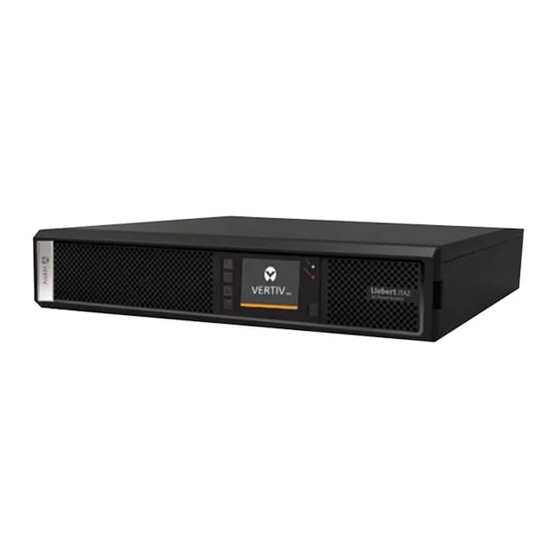
Vertiv™ Liebert® ITA2 1-3 kVA User Manual 3.3.2 Product Components Front panel As shown in Figure 3.2 below, the UPS front panel provides ventilation holes, operation and display panel, LED indicators, and functional keys. Figure 3.2 UPS front panel Parameter... - Page 18 As shown in Figure 3.3 below , the UPS rear panel provides dry contact port, I/O outlet, battery module port, Intellislot port, Ethernet port, USB port, and REPO port. Figure 3.3 Vertiv™ Liebert® ITA2 (1 kVA) UPS rear panel ...
- Page 19 Vertiv™ Liebert® ITA2 1-3 kVA User Manual Table 3.2 Vertiv™ Liebert® ITA2 1-3 kVA UPS rear panel details Parameter Description Input outlet Output outlet Battery module port Intellislot port (DB9) Ethernet port USB port Battery module number detection port REPO port...
-
Page 20: Operating Principal
Vertiv™ Liebert® ITA2 1-3 kVA User Manual 3.4 Operating Principal The operating principle of the Vertiv™ Liebert® ITA2 1-3 kVA UPS is shown in Figure 3.6 below. Figure 3.6 Vertiv™ Liebert® ITA2 (1-3 kVA) UPS operating principle Parameter Description... -
Page 21: Ups State And Operation Mode
LED Indicators on page 63 . The Vertiv™ Liebert® ITA2 1-3 kVA UPS state and operation mode include Normal mode, Bypass mode, Battery mode, ECO mode, Fault state and Maintenance Bypass mode. The operation schematic diagrams of Normal mode, Bypass mode, Battery mode, and Maintenance Bypass mode are shown in Figure 3.7 on the next page to Figure 3.9 on page 18. -
Page 22: Normal Mode
The operation mode is Normal mode. In Normal mode, the run indicator (green) is on, the alarm indicator is off, and the buzzer is silence. Figure 3.7 Vertiv™ Liebert® ITA2 1-3 kVA UPS operating principle (Normal mode) Parameter... -
Page 23: Bypass Mode
In Bypass mode, the run indicator (green) is on, alarm indicator (yellow) is on, and the buzzer beeps every second. The 'Current' page in LCD will display 'On Bypass'. Figure 3.8 Vertiv™ Liebert® ITA2 1-3 kVA UPS operating principle (Bypass mode) Parameter... -
Page 24: Battery Mode
In Battery mode, the run indicator (green) is on, alarm indicator (yellow) is on, and the buzzer beeps every second. The 'Current' page in LCD will display 'On Battery'. Figure 3.9 Vertiv™ Liebert® ITA2 1-3 kVA UPS operating principle (Battery mode) Parameter Description... -
Page 25: Eco Mode (For Ups Equipped With Battery Only)
UPS is first put into operation to ensure it can provide adequate backup time. NOTE: The Vertiv™ Liebert® ITA2 (1-3 kVA) UPS supports a cold start function, while this function is activated, UPS can be powered using battery mode without the availability of an input power supply. - Page 26 Vertiv™ Liebert® ITA2 1-3 kVA User Manual This page intentionally left blank 3 Product Introduction...
-
Page 27: Ups Installation
Vertiv™ Liebert® ITA2 1-3 kVA User Manual 4 UPS Installation This chapter introduces the installation, cable connection of the Vertiv™ Liebert® ITA2 1-3 kVA UPS. Each site has its own distinct feature, so this chapter provides general installation procedures and methods for the installation engineer who should conduct the installation according to the actual conditions. -
Page 28: Unpacking And Inspection
Place the cardboard box vertically, unpack the cardboard box, and remove the UPS. Refer to the Figure 4.1 below. Refer to Table 4.1 below for the UPS size and weight with package details. Table 4.1 Vertiv™ Liebert® ITA2 1-3 kVA UPS size and weight (with package) Specification Size (W×D×H) mm (Gross weight) ( KG) 18.8 (Standard back-up) -
Page 29: Installation Preparation
Vertiv™ Liebert® ITA2 1-3 kVA User Manual 4.3 Installation Preparation 4.3.1 Location To extend the UPS service-life, the selected location must comply with following: 1. Convenient wiring 2. Adequate operator access area 3. Good ventilation to meet the heat dissipation requirements 4. - Page 30 Vertiv™ Liebert® ITA2 1-3 kVA User Manual Space reserved Figure 4.2 Installation clearances (top view of rack installation) WARNING! The UPS should only be installed on the concrete surface or other non-flammable surfaces. NOTE: As shown in Figure 4.3 on page 28, the demonstration of the clearance between the rear panel...
- Page 31 Vertiv™ Liebert® ITA2 1-3 kVA User Manual Battery room A small amount of hydrogen and oxygen will be generated at the end of battery charging, therefore, you must ensure that the fresh air ventilation of the battery installation environment meets the EN50272-2001 requirements.
-
Page 32: Installation Tools
Vertiv™ Liebert® ITA2 1-3 kVA User Manual 4.3.3 Installation Tools WARNING! The installation tools utilized in live operation must be properly insulated for safety purpose. Tools in Table 4.2 below are for reference only; please follow the actual requirement for on- site installation and connection. - Page 33 Vertiv™ Liebert® ITA2 1-3 kVA User Manual Table 4.2 List of installation tools (continued) Name Drawing Name Drawing Insulating shoes Antistatic gloves Electrician knife Cable tie Insulating tape Insulating gloves Crimping plier Heat shrinkable tube Insulated torque Torque screwdriver wrench...
-
Page 34: External Protective Devices
Vertiv™ Liebert® ITA2 1-3 kVA User Manual 4.4 External Protective Devices The circuit breaker or other protective devices must be installed at the external AC input end of the UPS. This section provides the general guidance for qualified installation engineer. The qualified installation engineer should comply with the local wiring regulations and other related standards. -
Page 35: Battery Input
Vertiv™ Liebert® ITA2 1-3 kVA User Manual 4.4.3 Battery Input If the Vertiv battery module is selected, the battery module is equipped with an overcurrent protection device. Otherwise, the battery module shall provide DC compatible circuit breaker to provide over-current protection for UPS and its batteries. - Page 36 Vertiv™ Liebert® ITA2 1-3 kVA User Manual 2. If battery module installation is necessary, take out other support base extensions delivered with the battery module, and then assemble the support base extensions and the support bases through the fastenings, as shown in Figure 4.5 below.
- Page 37 Vertiv™ Liebert® ITA2 1-3 kVA User Manual 3. Place the UPS on the support bases and support base extensions, as shown in Figure 4.6 below. The two sets of support bases are placed as far apart as possible to prevent the UPS from toppling.
-
Page 38: Rack Installation
Vertiv™ Liebert® ITA2 1-3 kVA User Manual 4.5.2 Rack Installation Installation procedures for UPS 1. Use eight M4×8 screws to fix the two brackets (accessories) respectively on both sides of the UPS front panel, as shown in Figure 4.7 below. - Page 39 Vertiv™ Liebert® ITA2 1-3 kVA User Manual 2. Install the guide rails The UPS adopts 2U guide rails for installation, and the installation procedures are as follows: a. Take out the guide rails (one left guide rail and one right guide rail), guide rail screws from the package, distinguish the left guide rail and right guide rail according to Figure 4.8...
- Page 40 Vertiv™ Liebert® ITA2 1-3 kVA User Manual b. Adjust the length of the guide rail according to the dimensions of the rack. c. Align the installation holes of the guide rail with the square holes of the rack, fix the guide rail onto the rack through the guide rail screws (totally eight), each left guide rail and right guide rail need four guide rail screws, as shown in Figure 4.10 below.
- Page 41 Vertiv™ Liebert® ITA2 1-3 kVA User Manual The guide rail installation is finished, as shown in Figure 4.11 below. Figure 4.11 Guide rail installation completed 4 UPS Installation...
- Page 42 Vertiv™ Liebert® ITA2 1-3 kVA User Manual 3. Place the UPS on the guide rails in the rack and push it completely into the rack. Use four screws to fix the UPS in the rack through the brackets, as shown in Figure 4.12 below.
- Page 43 Vertiv™ Liebert® ITA2 1-3 kVA User Manual Installation procedures for UPS with battery modules 1. The battery module installation method is exactly the same as the UPS installation method. Repeat the above installation steps, install the battery modules and UPS to the rack one by one (4 battery modules are installed here).
-
Page 44: Connecting Power Cables
Vertiv™ Liebert® ITA2 1-3 kVA User Manual 4.6 Connecting Power Cables The rear panel of the UPS provides an input plug and an output socket, refer to the section 3.3.2 Product Components on page 11 for details. If the battery cabinet is configured, the battery cable is shipped with the battery cabinet. -
Page 45: Connecting Battery Cables
Vertiv™ Liebert® ITA2 1-3 kVA User Manual 4.6.2 Connecting Battery Cables NOTE: The batteries in the battery cabinet must be of the same manufacturer, the same model, the same capacity, and each battery rated voltage of 12 V. NOTE: The external battery capacity limit of 1 kVA (long back-up) is not less than 7 Ah, factory default 7 Ah;... - Page 46 Vertiv™ Liebert® ITA2 1-3 kVA User Manual Connecting long backup model and customer battery cabinet The recommended type of wire diameter and OT terminal for connecting the long backup model and user battery cabinet are shown in Table 4.4 below.
- Page 47 Vertiv™ Liebert® ITA2 1-3 kVA User Manual Figure 4.14 Battery string connection principal diagram Parameter Description Battery module First block Second block Third block Sixteenth block BAT+ BAT- 4 UPS Installation...
- Page 48 Vertiv™ Liebert® ITA2 1-3 kVA User Manual This page intentionally left blank 4 UPS Installation...
-
Page 49: Ups Operation Instructions
Vertiv™ Liebert® ITA2 1-3 kVA User Manual 5 UPS Operation Instructions This chapter gives a detailed description of the Vertiv™ Liebert® ITA2 1-3 kVA UPS operation procedures. During the operation, the buzzer alarm may appear, at this point, you can press the key for three seconds to silence. -
Page 50: Ups Start-Up
Vertiv™ Liebert® ITA2 1-3 kVA User Manual 5.1 UPS Start-Up The start-up procedures must be performed only after the installation is completed, the system has been commissioned by an authorized engineer, and the external input MCBs are closed. WARNING! This procedure results in the application of the mains voltage to the UPS output terminals. -
Page 51: Initial Start-Up Guidance
Vertiv™ Liebert® ITA2 1-3 kVA User Manual 5.2 Initial Start-up Guidance When the Vertiv™ Liebert® ITA2 1-3 kVA UPS is in the initial start-up state, the interface shown in Figure 5.1 below is displayed to guide the user to set basic parameters of the UPS. - Page 52 Vertiv™ Liebert® ITA2 1-3 kVA User Manual Output and battery parameters page The parameters such as the output voltage, output frequency, and total Ah are displayed on the 'initial start-up guidance' page (These settings can be changed according to the number of batteries connected).
- Page 53 Vertiv™ Liebert® ITA2 1-3 kVA User Manual Finish page The interface shown in Figure 5.4 below will appear. Click Finish to enter the Flow page, then the user can operate the UPS normally. Figure 5.4 Initial start-up guidance (Finish page)
-
Page 54: Transfer Procedures Between Operation Modes
5.3.1 Transfer from Normal Mode to Battery Mode The Vertiv™ Liebert® ITA2 1-3 kVA UPS will usually run in Normal mode unless the mains are disconnected; After the mains supply is disconnected, the UPS will automatically enter the battery mode. If it is necessary to switch the UPS to normal mode and restore the power supply, UPS will transfer to normal mode again. - Page 55 Vertiv™ Liebert® ITA2 1-3 kVA User Manual Figure 5.6 Bypass normal interface (Turning on UPS/Turning off UPS) Figure 5.7 Bypass normal interface (To the Bypass) Figure 5.8 Bypass normal interface (Turn off UPS) 5 UPS Operation Instructions...
-
Page 56: Transfer From Bypass Mode To Inverter Mode
Vertiv™ Liebert® ITA2 1-3 kVA User Manual In Inverter mode, press and hold the power button. If the bypass is abnormal, then the interface shown in Figure 5.9 below is displayed, select 'YES' to shut down the UPS output. ... - Page 57 Vertiv™ Liebert® ITA2 1-3 kVA User Manual Figure 5.11 ECO mode not turned on (Turn on UPS) Figure 5.12 ECO mode not turned on (Turn off UPS) IIf the ECO is turned on (activated), the interface shown in Figure 5.13 below will appear. Select 'YES' to shut down the UPS output.
-
Page 58: Ups Complete Shutdown
MCB must be unplugged in order to remove all mains power from the UPS. 5.6 Auto Restart The Vertiv™ Liebert® ITA2 1-3 kVA UPS deploy the auto restart function in two conditions: with battery, and without battery. -
Page 59: Language Selection
Vertiv™ Liebert® ITA2 1-3 kVA User Manual 5.7 Language Selection The LCD menus are available in two languages: Chinese and English. The procedures for selecting the preferred language are as follows: 1. On the main menu screen, press the key to switch the cursor to select 'Settings', then press key to confirm it. - Page 60 Vertiv™ Liebert® ITA2 1-3 kVA User Manual 3. Press the key to highlight the language, refer to Figure 5.16 below. Figure 5.16 (Monitor) Language selection 4. Press the key to select the preferred language, then press key to confirm it. The LCD contents will be the language selected.
-
Page 61: Changing Current Date And Time
Vertiv™ Liebert® ITA2 1-3 kVA User Manual 5.8 Changing Current Date and Time The following procedures are required to change the system date and time: 1. On the main menu screen, press the key to switch the cursor to select 'Settings', then press key to confirm it. - Page 62 Vertiv™ Liebert® ITA2 1-3 kVA User Manual 3. Press the key and then press the key to highlight the date and time, refer to Figure 5.19 below and Figure 5.20 below. Figure 5.19 Selection of date and time (Changing Current Date).
-
Page 63: Setting Password
Vertiv™ Liebert® ITA2 1-3 kVA User Manual 5.9 Setting Password The default password for the Settings page is 111111. It is a must to enter the current password first, and then change it to the preferred password. However, it is recommended to set the password to the default value to protect your system and devices. - Page 64 Vertiv™ Liebert® ITA2 1-3 kVA User Manual The user can observe the following procedures to change password: 1. Press the key to move the cursor to the 'Monitor', refer to the Figure 5.23 below. Figure 5.23 Monitor interface (Setting password) ...
- Page 65 Vertiv™ Liebert® ITA2 1-3 kVA User Manual 3. Press the key, then the interface shown in Figure 5.25 below is displayed. Figure 5.25 Password for settings 4. Input the existing password, then press key to confirm it, and then it is required to input a new password into the system.
- Page 66 Vertiv™ Liebert® ITA2 1-3 kVA User Manual 5. After inputting the new password, press key to confirm it, then the interface shown in the Figure 5.27 below is displayed. It is required to confirm the new password in the system.
-
Page 67: Operation And Display Panel
Vertiv™ Liebert® ITA2 1-3 kVA User Manual 6 Operation and Display Panel This chapter describes the functions and use of the components on the UPS operation and display panel and provides LCD display information, including the LCD screen types, detailed menu messages, prompt windows messages and UPS alarm list. - Page 68 Vertiv™ Liebert® ITA2 1-3 kVA User Manual Figure 6.2 Operation and display panel (2) Parameter Description Menu keys Run indicator Alarm indicator Power button NOTE: The device has a gravity sensor function; thus the LCD display direction will be changed according to the device layout mode.
-
Page 69: Led Indicators
Vertiv™ Liebert® ITA2 1-3 kVA User Manual 6.1.1 LED Indicators The LED indicators consist of the run indicator and alarm indicator. Table 6.1 belowdescribes these indicators. Table 6.1 Description of LED indicators Indicator Color State Meaning UPS has output Run indicator... -
Page 70: Lcd And Functional Keys
Vertiv™ Liebert® ITA2 1-3 kVA User Manual 6.1.3 LCD and Functional Keys The operation and display panel includes five functional keys, the respective functions are described in Table 6.3 below. Table 6.3 Description of control buttons Functional key Silk print... - Page 71 Vertiv™ Liebert® ITA2 1-3 kVA User Manual Figure 6.3 LCD screen Parameter Description ECO mode Ambient temperature and Ambient humidity (Displayed only when the sensors are connected) Date and time The LCD screen provides a user-friendly interface. The user-friendly and menu-driven LCD allows you to...
-
Page 72: Lcd Menu Structure
Vertiv™ Liebert® ITA2 1-3 kVA User Manual 6.2 LCD Menu Structure Figure 6.4 LCD menu structure 6.3 LCD Screen Types 6.3.1 Start Screen Upon UPS start-up, the UPS executes the system self-test, and the start screen is displayedand remains for approximately 10 seconds, as shown in Figure 6.5 below. -
Page 73: Flow Screen
Vertiv™ Liebert® ITA2 1-3 kVA User Manual 6.3.2 Flow Screen After the completion of the self-test of the UPS, the flow screen is displayed as shown in Figure 6.6 below. The flow screen displays the total status view of the UPS. The parameters displayed on the flow screen include input, bypass, rectifier, battery, inverter, and output. -
Page 74: Submenu Screen
Vertiv™ Liebert® ITA2 1-3 kVA User Manual 6.3.4 Submenu Screen The submenu screen contains the UPS parameters and item settings. After entering the submenu screen, if there is a tab control, just move the cursor to the tab. At this time, press the key to switch the tab. - Page 75 Vertiv™ Liebert® ITA2 1-3 kVA User Manual Figure 6.10 Status page (Bypass) Figure 6.11 Status page (Battery) 6 Operation and Display Panel...
- Page 76 Vertiv™ Liebert® ITA2 1-3 kVA User Manual Figure 6.12 Status page (Output) Figure 6.13 Status page (Load) 6 Operation and Display Panel...
- Page 77 Vertiv™ Liebert® ITA2 1-3 kVA User Manual Settings page The Settings page contains the Output, Battery, Parallel, Monitor, System, and Outlet. For details about the parameters setting, refer to the section Appendix A LCD Parameters Setting on page i . Refer to the images from Figure 6.14 below to Figure 6.22 on page 73.
- Page 78 Vertiv™ Liebert® ITA2 1-3 kVA User Manual Figure 6.17 Settings page (Battery) Figure 6.18 Settings page (Battery) (Scrolled) Figure 6.19 Monitor (Settings page) 6 Operation and Display Panel...
- Page 79 Vertiv™ Liebert® ITA2 1-3 kVA User Manual Figure 6.20 Monitor (Settings page) (Scrolled) Figure 6.21 Settings page (System) Figure 6.22 Settings page (System) (Scrolled) 6 Operation and Display Panel...
- Page 80 Vertiv™ Liebert® ITA2 1-3 kVA User Manual Control page Figure 6.23 Control page (Monitor) Figure 6.24 Control page (Turn ON/OFF/to BYPASS) The Control page contains the Turn ON/OFF/to BYPASS, and Manual battery test. Refer to the in Figure 6.24 above.
- Page 81 Vertiv™ Liebert® ITA2 1-3 kVA User Manual Log page The Log page contains the Current and History. Refer to the image Figure 6.25 below to Figure 6.26 below. Figure 6.25 Log page (Monitor) Figure 6.26 Log page (History) ...
- Page 82 Vertiv™ Liebert® ITA2 1-3 kVA User Manual About page The About page contains the Product and Network. Refer to the images from Figure 6.27 below to Figure 6.30 on the facing page. Figure 6.27 About page (Monitor menu screen) ...
- Page 83 Figure 6.30 About page (Network) Maintain page NOTE: The Maintain page is only accessible to Vertiv service engineers and it is required to enter the correct password to proceed with th maintenance operation. 6 Operation and Display Panel...
-
Page 84: Default Screen
Vertiv™ Liebert® ITA2 1-3 kVA User Manual 6.3.5 Default Screen During the UPS operation, if there is no alarm within two minutes, the default screen shown in Figure 6.31 below will appear. On the default screen, if there is an alarm or a fault, or the user press any key, the Flow screen will appear again. -
Page 85: Prompt Window
Vertiv™ Liebert® ITA2 1-3 kVA User Manual 6.4 Prompt Window A prompt window is displayed during the operation of the system to alert the user to certain conditions and/or to request the user's confirmation of a command or other operation. The prompts and their meanings are listed in Table 6.4 below. -
Page 86: List Of Ups Alarm And Fault Message
Vertiv™ Liebert® ITA2 1-3 kVA User Manual 6.5 List of UPS Alarm and Fault Message Table 6.5 below gives all UPS alarm and fault messages based on the 'Current' and 'History' menus. Table 6.5 UPS alarm message list Alarm message Description Test result The rectifier and charger are off due to the mains voltage and frequency exceeding normal renege. - Page 87 Check the communication cables are normal fails NOTE: If the alarm is caused by the setting value through the software by the Vertiv authorized engineer, and if there is any requirement to change the setting values, please contact the Vertiv representative.
- Page 88 Vertiv™ Liebert® ITA2 1-3 kVA User Manual This page intentionally left blank 6 Operation and Display Panel...
-
Page 89: Communication
Vertiv™ Liebert® ITA2 1-3 kVA User Manual 7 Communication This chapter mainly describes the Vertiv™ Liebert® ITA2 1-3 kVA UPS communication. The communication ports include intelligent card port, dry contact port, built-in port, DB9 port, and USB port. NOTE: It is recommended to use a signal cable length of less than 3 m and maintain distance from the power cable. - Page 90 Vertiv™ Liebert® ITA2 1-3 kVA User Manual Webpage monitoring function Open the browser (such as Microsoft Edge), and input the IPv4 address at the address bar to the login interface. After inputting the correct username and password (default name: user, password: 111111), you can monitor the UPS working status.
-
Page 91: Connecting Serial Port Communication Cables
SIC card is a network management card, which makes the intelligent devices (such as UPS, air conditioner, static transfer system (STS), sever power management system (SPM), and so on) produced by Vertiv have network communication capability. The SIC card can also be used with the Network Shutdown designed by Vertiv to provide safe automatic shutdown function for the computer, in which the Network Shutdown has been installed, to protect data and reduce loss. - Page 92 The RDU-SIC card is a network management card. It can build intelligent equipment (such as UPS and PDU) developed by Vertiv to have the capacity for network communication. The SIC card can also connect to the environmental monitoring equipment, including IRM series or 1-Wire series temperature sensor, temperature, and humidity sensor or dry contact signal input and detecting sensors.
-
Page 93: Maintenance
• Disconnect input power prior to connecting or disconnecting battery terminals. • If the battery kit is damaged in any way or shows signs of leakage, contact your Vertiv representative immediately. • Handle, transport, and recycle batteries in accordance with local regulations. -
Page 94: Fan Maintenance
Vertiv™ Liebert® ITA2 1-3 kVA User Manual This chapter describes UPS maintenance, including fan maintenance, battery maintenance, UPS cleaning, UPS state check, and UPS function check. NOTE: Never attempt to carry out maintenance on the UPS while it is online. Ensure that the UPS has been switched off completely when performing any internal maintenance operations. - Page 95 As the provider of the lead-acid battery, Vertiv has built a perfect service network and recycling system for the waste battery to assist users to deal with the waste battery by law. Contact the Vertiv representative for detailed information about the recycling system for the waste battery.
-
Page 96: Cleaning Ups
Vertiv™ Liebert® ITA2 1-3 kVA User Manual 8.4 Cleaning UPS It is recommended to follow the below steps in order to ensure free airflow inside the UPS: Clean the UPS periodically, especially the ventilation holes. If necessary, clean the UPS with a vacuum cleaner. -
Page 97: Options
Table 9.1 Option list Model or Option name Remark description Remark It can increase the backup time of the Vertiv™ ITA2 1-3 kVA UPS, one for each model, 3 in Battery module total Battery Connection cables Used for connection between battery module and UPS or both battery modules. The... - Page 98 Vertiv™ Liebert® ITA2 1-3 kVA User Manual This page intentionally left blank 9 Options...
-
Page 99: Technical Specifications
Vertiv™ Liebert® ITA2 1-3 kVA User Manual 10 Technical Specifications The technical specifications are listed in Table 10.1 below. Table 10.1 Technical specifications Specifications (both standard and long backup model) Item 1 kVA 2 kVA 3 kVA Rated voltage 220 Vac... - Page 100 Vertiv™ Liebert® ITA2 1-3 kVA User Manual Table 10.1 Technical specifications (continued) Specifications (both standard and long backup model) Item 1 kVA 2 kVA 3 kVA Noise Front panel less than 50 dB, the rear panel and side panel less than 48 dB...
-
Page 101: Appendices I
Vertiv™ Liebert® ITA2 1-3 kVA User Manual 11 Appendices Appendix A: LCD Parameters Setting Table i.1 LCD Parameters Setting Menu Item Setting range Default setting Auto restart Disable, Enable Enable Auto restart delay 0 to 999 seconds Guaranteed shutdown Disable, Enable Disable Remote control... - Page 102 Vertiv™ Liebert® ITA2 1-3 kVA User Manual Table i.1 LCD Parameters Setting (continued) Menu Item Setting range Default setting Voltage selection 220 V, 230 V, 240 V 220 V Startup on bypass Disable, Enable Disable Auto, By Pena; Auto, BypDisa;...
- Page 103 Vertiv™ Liebert® ITA2 1-3 kVA User Manual Table i.1 LCD Parameters Setting (continued) Menu Item Setting range Default setting Language English, Chinese English Date YYYY-MM-DD 2000-01-01 Time HH:MM:SS 00:00:00 Display orientation Auto-rotate, Horizontal, Vertical Auto-rotate Audible alarm Enable, Disable Enable...
- Page 104 Vertiv™ Liebert® ITA2 1-3 kVA User Manual This page intentionally left blank 11 Appendices...
-
Page 105: Appendix B: Glossary
Vertiv™ Liebert® ITA2 1-3 kVA User Manual Appendix B: Glossary Alternating Current Circuit Breaker Cross Sectional Area Direct Current Dual In-line Package Digital Signal Processor Battery Module Electromagnetic Compatibility Electromagnetic /interference End-Of-Discharge Emergency Power Off Input/Output Load Bus Synchronization Liquid Crystal Display... - Page 106 Vertiv™ Liebert® ITA2 1-3 kVA User Manual This page intentionally left blank...
- Page 107 Vertiv™ Liebert® ITA2 1-3 kVA User Manual...
- Page 108 Vertiv.com © 2023 Vertiv Group Corp. All rights reserved. Vertiv™ and the Vertiv logo are trademarks or registered trademarks of Vertiv Group Corp. All other names and logos referred to are trade names, trademarks or registered trademarks of their respective owners.
Need help?
Do you have a question about the Liebert ITA2 and is the answer not in the manual?
Questions and answers