Table of Contents
Advertisement
Advertisement
Table of Contents

Subscribe to Our Youtube Channel
Related Manuals for Vertiv Liebert ITA2-08KRT208


Summary of Contents for Vertiv Liebert ITA2-08KRT208
- Page 1 Liebert® ITA2™ 8-10kVA, 60Hz, 208/220V Three-Phase UPS User Manual...
- Page 2 The products covered by this instruction manual are manufactured and/or sold by Vertiv This document is the property of Vertiv and contains confidential and proprietary information owned by Vertiv. Any copying, use or disclosure of it without the written permission of Vertiv is strictly prohibited.
-
Page 3: Table Of Contents
TABLE OF CONTENTS CONTACTING VERTIV FOR SUPPORT ..... . INSIDE FRONT COVER ™ IMPORTANT SAFETY INSTRUCTIONS ........1 SAVE THESE INSTRUCTIONS . - Page 4 UPS Alarm Message List..............54 Vertiv | Liebert ®...
- Page 5 Figure 44 Confirm new password ............. . 37 Vertiv | Liebert ®...
- Page 6 Table 17 UPS alarm messages ..............54 Vertiv | Liebert ®...
-
Page 7: Important Safety Instructions
Risk of exposure to hazardous chemical. Can cause illness or death. This product can expose you to chemicals including nickel, (metallic), which known to the State of California to cause cancer. For further information, go to www.P65Warnings.ca.gov Vertiv | Liebert ITA2 User Manual | ®... - Page 8 Materials sold hereunder cannot be used in the patient vicinity (e.g., use where UL, cUL or IEC 60601-1 is required). Medical applications such as invasive procedures and electrical life support equipment are subject to additional terms and conditions. Vertiv | Liebert ITA2 User Manual | ®...
- Page 9 The “crossed-out wheelie bin symbol” is placed on this product to encourage you to recycle whenever possible. NOTE The Liebert ITA2 has no user-serviceable parts. If the UPS malfunctions and requires service, contact Vertiv Support at 800-543-2378 or your local Vertiv representative. Vertiv | Liebert ITA2 User Manual | ®...
-
Page 10: Introduction
INTRODUCTION The Liebert ITA2 uninterruptible power system (UPS) is an intelligent, on-line UPS with sine wave output developed by Vertiv. The UPS offers reliable, high quality AC power to small-scale computer centers, networks, communication systems, automatic control systems and similar sensitive electronic equipment. -
Page 11: Appearance And Components
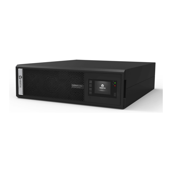
Components—Front Panel As shown in Figure 1, the UPS front panel provides ventilation holes, operation and display panel, LED indicators and function keys. Figure 1 UPS front panel VERTIV 1. Ventilation Holes 2. LED Indicators Operation and display 4 Function 1.3.2 Components—Rear Panel... -
Page 12: Major Components
Risk of unauthorized changes and improper service. Can cause property damage, injury or death. The Liebert ITA2 has no user-serviceable parts. Contact Vertiv Support at 800-548-2378 in the event of any malfunction that requires service. Unauthorized personnel must not open the UPS chassis cover. -
Page 13: Transient Voltage Surge Suppression (Tvss) And Emi/Rfi Filters
Mode, Bypass Mode, Battery Mode and Maintenance Bypass Mode are shown in Figures 4 through 7. NOTE Maintenance Bypass Mode is available only when the UPS system includes the optional MBC cabinet. Vertiv | Liebert ITA2 User Manual | ®... -
Page 14: Normal Mode
The run indicator (green) will be On, the alarm indicator will be Off and the buzzer will be silent. Figure 4 Normal Mode Bypass Static Input Switch Mains Rectifier/PFC Inverter Output Input Charger Battery Vertiv | Liebert ITA2 User Manual | ® ™... -
Page 15: Bypass Mode
Upon utility failure or voltage out of range, the battery will supply power to the load through the inverter. In Battery Mode, the run indicator will be green, the alarm indicator will be yellow and the buzzer will beep once every second. The Current Screen in the LCD will display On Battery. Vertiv | Liebert ITA2 User Manual | ®... -
Page 16: Auto Restart Mode
UPS overtemperature occurs. In UPS Fault state, the alarm indicator (red) will be On, the buzzer will beep continuously and the fault information will be displayed on the LCD. Vertiv | Liebert ITA2 User Manual | ®... -
Page 17: Maintenance Bypass Mode
The Maintenance Bypass Breaker is on the front panel of the Maintenance Bypass Cabinet (MBC). For details, refer to the Liebert ITA2 MBC user manual, SL-26252. The manual is available at Vertiv’s Web site: www.vertivco.com... -
Page 18: Single Ups Installation And Commissioning
Risk of improper installation. Can cause property damage, injury or death. The UPS must be installed according to the information contained in this chapter by properly trained and qualified personnel. If any problem is found, contact Vertiv Support immediately at 800-543-2378. -
Page 19: Moving The Ups
1050 Dearborn Drive P.O. Box 29186 Columbus, Ohio 43085 USA 2. Check the accessories and models against the delivery list. If any problem is found, notify your local Vertiv representative immediately. Moving the UPS The UPS cabinet can be moved manually by an adequate number of personnel or with mechanical lifting equipment. -
Page 20: Installation Preparation
Maintain at least 8" (200mm) clearance in the front and rear of the UPS (see Figure 9), to avoid obstructing the UPS ventilation and heat dissipation. Figure 9 Installation clearances 8" Wall (200mm) Top view of rack Vertiv | Liebert ITA2 User Manual | ® ™... -
Page 21: Installation Tools
In a dual-input system, separate protective devices should be installed for the rectifier and bypass inputs at the utility input power distribution panel. Main/Bypass Back-Feed Protection The UPS has main/bypass back-feed protection function in the event of a fault. Vertiv | Liebert ITA2 User Manual | ®... -
Page 22: Battery Input
The earth leakage current fed by the RFI filter in the UPS ranges from 3.5mA to 100mA. Vertiv recommends verifying the sensitivity of each differential device of the upstream input power distribution and downstream power distribution (to load). -
Page 23: Figure 11 Connecting The Support Base With Support Base Extension
4. Place the UPS on the support bases and support base extensions, as shown in Figure 13. Figure 13 UPS and battery cabinet installation complete 1. Support Base 2. UPS 3. Battery Cabinet, 4 Vertiv | Liebert ITA2 User Manual | ®... -
Page 24: Rack Installation
Align the installation holes of the guide rail with the square holes of the rack, fix the guide rail onto the rack through the guide rail screws (total of eight), each left guide rail and right guide rail requires four guide rail screws, as shown in Figure 16. Vertiv | Liebert ITA2 User Manual | ®... -
Page 25: Figure 16 Installing The Guide Rail
The guide rail holder must be nearer the front of the rack. Each end of a guide rail has four installation holes (see Figure 15). Do not use the two installation holes in the middle when attaching the guide rail. Vertiv recommends using the top and bottom installation holes. -
Page 26: Connecting Power Cables
Risk of improper installation. Can make rack top-heavy and cause a tipping hazard. The battery cabinets are heavier than the Liebert ITA2 UPS. Vertiv recommends installing the battery cabinets as near the bottom of the rack as possible to maintain a low center of gravity. Install the UPS above the battery cabinets. -
Page 27: Connecting I/O Cables
After the power cables are connected, the protective cover board of the I/O terminal block must be reinstalled to remove the electric shock hazard. Power Distribution Mode There are two modes for UPS power distribution: • optional Maintenance Bypass Cabinet, and • self-distribution. Vertiv | Liebert ITA2 User Manual | ® ™... -
Page 28: Single-Input Configuration
• Phase C from the upstream feeder panel to UPS Terminal 13 • Neutral from the upstream feeder panel to UPS Terminal 14 or 15 • The safety equipment ground cable from upstream feeder panel to UPS ground stud 10 Vertiv | Liebert ITA2 User Manual | ®... -
Page 29: Dual-Input Configuration
Risk of electrical shock. Can cause equipment damage, injury and death. Before beginning installation, verify that all external overcurrent protection devices are open (Off), and that they are locked out and tagged appropriately to prevent activation during the installation. Vertiv | Liebert ITA2 User Manual | ®... - Page 30 • Neutral cable from UPS Terminal 5 (6) to the downstream distribution panel neutral bus • The safety equipment ground cable from UPS Ground Stud 1 to the downstream distribution panel ground bus Replace the conduit box cover and secure it. Vertiv | Liebert ITA2 User Manual | ®...
-
Page 31: Connecting Battery Cables
To install the insulating plates, connect the external cable to the battery terminals as shown in Figure 22 Vertiv | Liebert ITA2 User Manual | ®... -
Page 32: Figure 22 Battery Insulating Plate
Before installation, inspect the appearance and accessories of the battery, and cabinet and if there are any signs of damage, contact Vertiv Services at 800-543-2378. 2. Maintain at least 10mm clearances between the front, rear, side panels of the battery and the wall or adjacent equipment to keep well-ventilated. -
Page 33: Figure 23 Cables Between Liebert Ita2 And Battery Cabinets
5. Terminal A of Battery Cabinet 1; Cabinet 2; Cabinet 1 Battery String 2 Battery String 2 The cable connections between the battery cabinet and the UPS are shown in Figure 24. Vertiv | Liebert ITA2 User Manual | ® ™... -
Page 34: Figure 24 Cable The Ups To Two Battery Strings In Parallel
12. Communication Port 1 Cabinet 2 Cabinet 3 Cabinet 4 of Battery Cabinet 3 13. RJ-45 Communication 14. Communication Port 2 15. Communication Port 1 Cables of Battery Cabinet 1 of Battery Cabinet 1 Vertiv | Liebert ITA2 User Manual | ® ™... -
Page 35: Operation And Display Panel
1. LCD 2. Run 3. Alarm Indicator Indicator 4. Power 5. Menu Keys Button NOTE The LCD automatically changes orientation depending on how the UPS is installed, either rack or tower. Vertiv | Liebert ITA2 User Manual | ® ™... -
Page 36: Led Indicators
Move to Next Page, reduce value, move right in Down tower configuration. Escape Go Back or Escape Used to Power On, Power Off or transfer to Power Bypass mode Vertiv | Liebert ITA2 User Manual | ® ™... -
Page 37: Lcd Menu Structure
LCD Menu Structure Figure 27 LCD menu structure Startup Mimic Main Menu Status Control Maintain Settings About Input Battery Load Current Bypass Output Parallel History Input Parallel System Product Network Battery Monitor Output Vertiv | Liebert ITA2 User Manual | ® ™... -
Page 38: Lcd Screen Types
The working modes are shown in color and the invalid modes in gray. Figure 29 UPS Mimic At the UPS Mimic page, press the Enter button to enter the main menu screen. Vertiv | Liebert ITA2 User Manual | ®... -
Page 39: Main Menu Screen
For details about the submenu screen, see following pages. Status Screen The Status screen contains five tabs for the Input, Bypass, Battery, Output and Load to display the voltages, currents, frequencies and other UPS parameters. Vertiv | Liebert ITA2 User Manual | ®... -
Page 40: Figure 31 Status Page Menus
Figure 31 Status page menus Vertiv | Liebert ITA2 User Manual | ® ™... -
Page 41: Figure 32 Settings Page Password
NOTE The default password (111111) must be entered before the UPS’s configuration or parameters can be changed. Vertiv recommends recording the password and storing it in an accessible location for later retrieval. For details about the parameters setting, refer to 3.6.1 - LCD Parameter Settings. -
Page 42: Figure 34 Settings Page Menus-Continued
Figure 34 Settings Page menus—continued Monitor Pg. 2 System Pg. 2 Vertiv | Liebert ITA2 User Manual | ® ™... -
Page 43: Figure 35 Control Page Menus
The Control page shows Turn ON/OFF/to BYPASS and Manual battery test, etc. See below: Figure 35 Control page menus Log Screen The Log Screen contains the Current and History. See below: Figure 36 Log Screen menus Vertiv | Liebert ITA2 User Manual | ®... -
Page 44: Figure 37 About Screen Menus
The About Screen shows information about Product and Network. See below: Figure 37 About Screen menus Maintain Screen NOTE The Maintain Screen is protected with a password. It is available only to Vertiv service engineers. Figure 38 Maintain Screen—Password required Vertiv | Liebert... -
Page 45: Language Selection
Figure 40. 4. Press the Enter key , move the cursor and press the key to change the date or time; see Figure 40. Vertiv | Liebert ITA2 User Manual | ®... -
Page 46: Setting The Password
4. Press the key to move the cursor to Monitor; see Figure 42. Press the Enter key , then press the key to select the Change settings password, see Figure 42. Vertiv | Liebert ITA2 User Manual | ® ™... -
Page 47: Figure 42 Monitor Interface-Change Settings Password
10. After re-entering the new password, press the Enter key ; the system will displays a notification that the password change succeeded. If the confirmation is incorrect, the display will prompt re-entry of the password and seek confirmation. See Figure 45. Vertiv | Liebert ITA2 User Manual | ®... -
Page 48: Lcd Parameter Settings
NOTE The correct password (default: 111111) must be entered before the UPS’s configuration or parameters can be changed. Vertiv recommends recording the password and storing it in an accessible location for later retrieval. 3.6.1 LCD Parameter Settings... - Page 49 Thursday, Friday, Saturday Battery test time HH:MM:SS 0:00:00 Discharge protect time 1~4320 (min) 4320 Equal charge enable NO, YES Temperature compensation Disable, Enable Disable Replace battery By HMI Interface Button Button Vertiv | Liebert ITA2 User Manual | ® ™...
- Page 50 IPv4 address — Subnet mask ddd.ddd.ddd.ddd ( 'd' is a decimal number) — Gateway address — The six-digit numeric password can be any Change settings password 111111 numeral 0 to 9. Vertiv | Liebert ITA2 User Manual | ® ™...
-
Page 51: Default Screen
Figure 46, will appear. At the default screen, if there is an alarm or a fault or if the user presses any key, the UPS Mimic Screen will reappear. Figure 46 Default screen Vertiv | Liebert ITA2 User Manual | ®... -
Page 52: Operating Instructions
Figure 47 Initial startup guidance, Pg. 1 Welcome Screen Press the Enter button to start the guide. Language, Date and Time This screen permits setting the language, date and time. Vertiv | Liebert ITA2 User Manual | ® ™... -
Page 53: Figure 48 Initial Startup Guidance
Figure 50 Initial startup guidance, Pg. 4 Finish Screen The interface shown in Figure 51 will appear. Click Finish to enter the UPS Mimic Screen. The the UPS will begin normal operation. Vertiv | Liebert ITA2 User Manual | ®... -
Page 54: Transfer Between Operation Modes
If the bypass power is outside normal operating range, the screen shown in will appear Figure 53 where the only selection is to Turn Off UPS and confirm the action and press the Enter key. Figure 52 Bypass normal interface Vertiv | Liebert ITA2 User Manual | ®... -
Page 55: Transfer From Bypass Mode To Inverter Mode
If the UPS is operating in Eco Mode, the screen shown in ll appear with the only choice is Turn Off UPS. To do so, confirm the action and press the Enter key. Figure 54 Transfer to Inverter Mode from Bypass Mode Vertiv | Liebert ITA2 User Manual | ®... -
Page 56: Repo
An interface with the REPO circuit must be field-supplied to allow disconnecting the UPS input feeder breaker to remove all sources of power to the UPS and connected equipment to comply with national and local wiring codes and regulations. Vertiv | Liebert ITA2 User Manual | ®... -
Page 57: Communication
RS- 232 port, control port and USB port. NOTE Vertiv recommends using a signal cable less than 9 ft. (3m). Do not route the communication cable near power cables or batteries to prevent interference. Liebert IntelliSlot Port 5.1.1... -
Page 58: Connection Cables For Dry Contact Port
The EPO action of the UPS will shut down the rectifier, inverter and static bypass, but it does not disconnect input power from the UPS. To electrically isolate the UPS, disconnect the upstream input MBC when generating the EPO. Vertiv | Liebert ITA2 User Manual | ®... -
Page 59: Connecting Usb Communication Cables
Normally Open (N.O.) REPO connection. The factory-installed jumper must remain installed. NOTE Vertiv recommends using 0.82mm ~ 0.33mm (signal cable of 18AWG ~ 33AWG) copper core cable. Connecting USB Communication Cables A standard USB Type B port is provided to allow connection to a computer or network server (see Figure 2 for the location). -
Page 60: Connecting Multifunction Port
Connecting MultiFunction Port The control port adopts the standard RJ-45 port, which supports the Modbus/Jbus port and connects the Vertiv temperature/temperature and humidity sensor. The user can select Modbus/Jbus protocol function or sensor function via the Settings Screen of the control on the LCD. -
Page 61: Maintenance
Vertiv has a service network and recycle system to assist users to deal with the waste battery by law. Contact Vertiv Services at 800-543-2378 for information about recycling the waste battery. -
Page 62: Options
There is no operation or display panel on the front panel of the battery cabinet. The plastic panel can be removed; refer to the battery manual, SL-26250, which ships with the battery and is available at Vertiv’s Web site, www.vertivco.com The battery cabinet provides ventilation holes, battery ports and battery output switch on the rear panel. -
Page 63: Standard Battery Cabinet Backup Time With A Single Ups
Battery 7.2k 6.48k 5.76k 5.4k 5.04k 4.32k 3.6k 2.88k 2.16k 1.8k 1.44k 0.72k Strings 1020 Table 14 Backup time in minutes—10kVA/10kW Load Level Number 100% Of Battery Strings 10kW 7.5kW 2.5kW Vertiv | Liebert ITA2 User Manual | ® ™... -
Page 64: Specifications
Sea Level to 10,000 (3000) without derating Dimensions, 16.9 x 19.7 x 5.1 (430 x 500 x 130) W x D x H, in. Shipping 33.1 x 13.8 x 25.3 (842 x 350 x 642) (mm) Vertiv | Liebert ITA2 User Manual | ® ™... - Page 65 Table 15 Specifications Item Description 8kVA 10kVA 50.7 (23) Weight, lb. (kg) Shipping 70.5 (32) Vertiv | Liebert ITA2 User Manual | ® ™...
-
Page 66: Appendix A - Ups Prompts And Alarms
Bypass backfeed A bypass short circuit is detected while in Battery mode. Output off, voltage is not zero When there is no output, the system detects that the output has a voltage. Vertiv | Liebert ITA2 User Manual | ®... - Page 67 Check that the actual inverter load capacity, if overloaded, just reduce the load capacity, and the system will transfer to the inverter mode after five minutes with alarm cleared. Vertiv | Liebert ITA2 User Manual | ®...
- Page 68 The battery self-test or manual self-test finished. EOD turn off The inverter is Off due to EOD. Shut down the connected load. Guaranteed shutdown Under forced EOD mode, the battery discharging finished, then system shuts down. Vertiv | Liebert ITA2 User Manual | ®...
- Page 69 In parallel system, the alarm occurs when the UPS's self-adapting output frequency is System warning inconsistent. Solution: Power On again System fault The alarm occurs when model identification is incorrect. Contact service. Vertiv | Liebert ITA2 User Manual | ®...
- Page 70 NOTES Vertiv | Liebert ITA2 User Manual | ® ™...
- Page 71 Vertiv | Liebert ITA2 User Manual | ® ™...
- Page 72 Vertiv | Liebert ITA2 User Manual | ® ™...
- Page 74 © 2018 Vertiv Co. All rights reserved. Vertiv and the Vertiv logo are trademarks or registered trademarks of Vertiv Co. All other names and logos referred to are trade names, trademarks or registered trademarks of their respective owners. While every precaution has been taken to ensure accuracy and completeness herein, Vertiv Co.
Need help?
Do you have a question about the Liebert ITA2-08KRT208 and is the answer not in the manual?
Questions and answers