Table of Contents
Advertisement
Quick Links
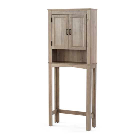
Model
9223GYWM (Rustic Gray
Date:
Lot number:
Product Inquiries - Installation Help
Just call (800) 892-3986 for parts and service. For faster service, have the model number
ready when calling.
THIS INSTRUCTION BOOKLET CONTAINS IMPORTANT SAFETY INFORMATION. PLEASE READ AND
Para instrucciones en español y francés, comience en la página 23.
Pour les instructions espagnoles et françaises, commencez à la page 23.
Pg 1 of 44
KEEP FOR FUTURE REFERENCE.
For Spanish and French instructions, start on page 23.
)
MCS 11/21/2019
(800) 892-3986
IS92230-I3
Advertisement
Table of Contents

Related Manuals for Better Homes and Gardens 9223GYWM


Summary of Contents for Better Homes and Gardens 9223GYWM
- Page 1 Model 9223GYWM (Rustic Gray Date: Lot number: Product Inquiries - Installation Help Just call (800) 892-3986 for parts and service. For faster service, have the model number ready when calling. THIS INSTRUCTION BOOKLET CONTAINS IMPORTANT SAFETY INFORMATION. PLEASE READ AND KEEP FOR FUTURE REFERENCE.
- Page 2 Before You Begin: Thank you for purchasing this product. Please identify all parts and hardware pieces before you begin. When laying out parts, place them on a soft surface to prevent scratching. If any pieces are missing, call our Toll Free Number 1-800-892-3986 between 8:00AM-5:00PM EST Monday through Friday.
- Page 3 List of Parts Top Panel Adjustable Shelf Fixed Shelf Middle Shelf Top Left Side Panel Top Right Side Panel Top Trim Magnet Block Hanging Rail Top Left Trim Top Right Trim Bottom Trim Top Support Rail Bottom Support Rail Right Leg Assembly Left Leg Assembly Door Back Panel...
- Page 4 List of Hardware Large Screw x 12 Nail x 22 x 14 Screw Cover Sticker x 20 Cambolt x 20 Cam Sticker x 16 Dowel x 30 Magnet Screw x 32 (used on pasrt 6, 7, & 8) Magnet Screw Hinge Magnet Strike Magnet Strike Screw...
- Page 5 Step 1 - Attaching the Magnet. • Insert cams (3) into the top trim (G), as shown. NOTE the direction of the cams (3). • With the magnet (15) facing down, attach it to the magnet block (H), as shown. •...
- Page 6 Step 3 - Installing Angle Blocks to the Top Side Panels. • Insert cams (3) into the top side panels (E and F), as shown. NOTE the direction of the cams (3). • Attach cambolts (2) to the top side panels (E and F) and angle blocks (8) to top side panels (E and F), as shown.
- Page 7 Step 4 - Installing Hinges. • Attach two hinges (6) to top right trim (K), as shown. DO NOT OVERTIGHTEN HINGE SCREWS (5)! • Repeat for the top left trim (J). unfinished edge Repeat for the top left trim (J). (800) 892-3986 IS92230-I3 Pg 7 of 44...
- Page 8 Step 5 - Attaching the Top Trim to the Top Side Panel. • Insert dowels (4) into the top right trim (K), as shown. • Attach the top right side panel (F) to the top right trim (K), as shown. DO NOT OVERTIGHTEN SCREWS (5)! •...
- Page 9 Step 6 - Attaching the Top Side Panels to the Fixed Shelf. • Insert dowels (4) into the top right and left side panels (E and F)and top trim (G). • Attach the fixed shelf (C) and the top trim (G) to the top side panels (E and F). •...
- Page 10 Step 7 - Installing Cambolts to the Top Panel. • Attach cambolts (2) to the top panel (A), as shown. unfinished edge Step 8 - Installing Cambolts to the Middle Shelf. • Attach cambolts (2) to the middle shelf (D), as shown. unfinished edge (800) 892-3986 IS92230-I3...
- Page 11 Step 9 - Attaching the Middle shelf. • Insert dowels (4) into the top side panels (E and F), as shown. • Attach the middle shelf (D) to the top side panels (E and F), as shown. (800) 892-3986 IS92230-I3 Pg 11 of 44...
- Page 12 Step 10 - Attaching the Top Panel. • Insert dowels (4) into the top side panels (E and F), as shown. • Attach the top panel (A) to the top side panels (E and F), as shown. • Tighten cams (3) by turning them clockwise approximately a half turn or until snug. DO NOT OVERTIGHTEN! (800) 892-3986 IS92230-I3 Pg 12 of 44...
- Page 13 Step 11 - Installing Cams to the Bottom Trim and Top Support Rail. • Insert cams (3) into the bottom trim (L) and the top support rail (M). NOTE the direction of the cams (3). NOTE the direction of the cams (3). Step 12 - Attaching Cambolts to the Leg Assemblies.
- Page 14 Step 13 - Attaching the Leg Assemblies to the Bottom Trim and Top Support Rail. • Attach the leg assemblies (O and P) to the bottom trim (L) and the top support rail (M), as shown. • Tighten cams (3) by turning them clockwise approximately a half turn or until snug. DO NOT OVERTIGHTEN! Back unfinished edge (800) 892-3986...
- Page 15 Step 14 - Attaching the Top assembly to the Bottom assembly. • Attach feet (20) to the legs, as shown. NOTE: If necessary, lightly tap the foot (20) with a hammer. • Carefully lay the cabinet body over and lay face up on the floor. •...
- Page 16 Step 15 - Carefully stand the assembly upright. RECOMMEND • NOTE: Hold the top panel (A) and slowly stand the assembly upright, RECOMIENDA as shown. RECOMMANDÉ Correct!! Incorrect!! (800) 892-3986 IS92230-I3 Pg 16 of 44...
- Page 17 Step 16 - Attaching the Doors. RECOMMEND • Attach the magnet strike (17) to door (W), as shown. DO NOT OVERTIGHTEN MAGNET RECOMIENDA STRIKE SCREW (18)! RECOMMANDÉ • Attach door (W) to the hinges (6), as shown. NOTE: DO NOT OVERTIGHTEN HINGE SCREWS (5)! •...
- Page 18 Step 17 - Hinge Adjustments. • Horizontal Adjustment, (IN AND OUT). Hinge Door • Vertical Adjustment, (UP AND DOWN). Hinge Door (800) 892-3986 IS92230-I3 Pg 18 of 44...
- Page 19 Step 18 - Attaching the Back Panel. RECOMMEND • We recommend two people carefully stand the assembly up. RECOMIENDA • With the seam side of back panel (X) facing out, attach to the back of the unit. RECOMMANDÉ • NOTE: Make sure the mounting holes are at the top and lined up with holes in the hanging rail (I), as shown.
- Page 20 Step 19 - Mounting the unit to the wall. RECOMMEND WARNING: BEFORE CUTTING OR DRILLING INTO ANY WALL SURFACE, VERIFY THE LOCATION OF ELECTRICAL, PLUMBING AND GAS LINES. CUTTING ANY OF THESE MAY CAUSE SERIOUS INJURY. • It is imperative that the unit be fastened to the wall for safety and stability. •...
- Page 21 Step 20 - Attaching the Bottom Support Rail. RECOMMEND • We recommend two people carefully place the assembly in the desired location. RECOMIENDA • Attach the bottom support rail (N) with the unfinished edge facing down, as shown. RECOMMANDÉ (800) 892-3986 IS92230-I3 Pg 21 of 44...
- Page 22 Step 21 - Attaching the Cam Stickers and Screw Caps. •Apply screw cover stickers (13) to screws (1) and cam stickers (14) to cams (3), as shown. x 14 x 16 Screw Cover Sticker (13) Cam Sticker (14) (800) 892-3986 IS92230-I3 Pg 22 of 44...
- Page 23 Modelo / Modèle 9223GYWM (Gris rústico / Gris rustique) Fecha: Date : Número de lote: Numéro de lot : Consultas sobre productos - Instalación Ayuda Simplemente llame al (800) 892-3986 para piezas y servicio. Si desea una servicio más rápido, al llamar tenga a mano el número de modelo.
- Page 24 Antes de que empiece: Muchas gracias por comprar este producto. Identifique todas las piezas y las piezas de ferretería antes de comenzar. Al distribuir las piezas, colóquelas sobre una superficie suave para evitar que se rayen. Si faltaran piezas, llame a nuestro número gratuito 1-800-892-3986 entre las 8:00 a.m.- 5:00 p.m., hora del este, de lunes a viernes.
- Page 25 Lista de Partes / Liste des pièces Paneles superior e inferior Panneau supérieur Repisa regulable Tablette amovible Repisa fija Tablette fixe Repisa central Tablette du milieu Panel lateral superior izquierdo Panneau latéral supérieur gauche Panel lateral superior derecho Panneau latéral supérieur droit Terminación superior Traverse supérieure Bloque de imán...
- Page 26 Lista de piezas de tornillería / Liste des pièces de montage Tornillo grands Clavo x 12 x 22 Vis longue Clou Adhesivo para cubierta de tornillo x 14 Perno para levas x 20 Pastille autocollante Boulon à cames cache-vis Adhesivo para leva Leva x 20 Pastille autocollante...
- Page 27 Paso 1: sujetar el imán. Étape 1 -raccordement de l’aimant. • Inserte las levas (3) dentro de la terminación superior (G), • Insérez des cames (3) dans la traverse supérieure (G), como se ilustra. TENGA EN CUENTA la orientación de las comme illustré.
- Page 28 Paso 3: instalar los bloques de ángulo en los paneles Étape 3 -installation les blocs en angles aux pan- laterales superiores. neaux latéraux supérieurs. • Inserte las levas (3) dentro de los paneles laterales • Insérez des cames (3) dans les panneaux latéraux superiores (E y F), como se ilustra.
- Page 29 Paso 4: instalar las bisagras. Étape 4 -installation des charnières. • Coloque dos bisagras (6) a la terminación superior • Montez deux charnières (6) à la traverse supérieure droite (K), izquierda (K), como se ilustra. ¡NO APRIETE LOS TORNILL0S DE comme illustré.
- Page 30 Paso 5: sujetar la moldura superior en el panel lateral Étape 5 -raccordement de la finition supérieure au superior. panneau latéral supérieur. • Inserte las clavijas (4) dentro de la terminación superior • Insérez des goujons (4) dans la traverse supérieure droite (K), derecha (K), como se ilustra.
- Page 31 Paso 6: sujetar los paneles laterales superiores a la Étape 6 -raccordement des panneaux supérieurs repisa fija. latéraux à la tablette fixe. • Inserte las clavijas (4) dentro de los paneles laterales • Insérez les goujons (4) dans les panneaux latéraux superiores derecho e izquierdo (E y F) y la terminación supérieurs droit et gauche (E et F) et dans la traverse superior (G).
- Page 32 Paso 7: instalar los pernos de leva en el panel superior. Étape 7 -installation des boulons à cames au panneau supérieur. • Fije los pernos de levas (2) al panel superior (A), como • Fixez des boulons à came (2) au panneau supérieur (A), se ilustra.
- Page 33 Paso 9: sujetar la repisa intermedia. Étape 9 -raccordement de la tablette médiane. • Inserte las clavijas (4) dentro de los paneles laterales • Insérez des goujons (4) dans les panneaux latéraux superiores (E y F), como se ilustra. supérieurs (E et F), comme illustré. •...
- Page 34 Paso 10: sujetar el panel superior. Étape 10 -raccordement du panneau supérieur. • Inserte las clavijas (4) dentro de los paneles laterales • Insérez des goujons (4) dans les panneaux latéraux superiores (E y F), como se ilustra. supérieurs (E et F), comme illustré. •...
- Page 35 Paso 11 - Instalación de levas en la moldura inferior Étape 11 - Installation des cames sur la garniture y el riel de soporte superior. inférieure et le rail de support supérieur. • Inserte las levas (3) en la moldura inferior (L) y el riel de •...
- Page 36 Paso 13 - Montaje de los ensambles de las patas a Étape 13 - Fixation des ensembles de pieds à la la moldura inferior y al riel de soporte superior. garniture inférieure et au rail de support supérieur. • Adjunte los ensambles de las patas (O y P) a la moldura •...
- Page 37 Paso 14 sujetar el montaje superior al montaje Étape 14 - raccordement de l’assemblage supérieur inferior. à l’assemblage du bas. • Fije pies (20) a las patas, como se ilustra. NOTA: Si fuese • Fixez les pieds (20) aux montants, comme illustré. necesario, golpee el pie (20) ligeramente con un martillo.
- Page 38 Paso 15: con cuidado, colocar el montaje en Étape 15 -placez minutieusement l’assemblage posición vertical. debout. RECOMIENDA • NOTA: Sostenga el panel superior (A) y lentamente • REMARQUE : redressez lentement le meuble en coloque el ensamble en posición vertical. le maintenant par le panneau supérieur (A).
- Page 39 Paso 16: sujetar las puertas. Étape 16 -raccordement des portes. • Fije la contrachapa de imán (17) a la puerta (W), • Fixez la gâche de l'aimant (17) à la porte (W), RECOMIENDA como se ilustra. ¡NO APRIETE EL TORNILLO PARA comme illustré.
- Page 40 Paso 17: ajustes de las bisagras. Étape 17 -ajustement des charnières. • Ajuste horizontal, (dentro y fuera). • Réglage horizontal, (dans et hors). Bisagra Charnière Puerta Porte • El ajuste vertical, (arriba y abajo). • Réglage vertical, (haut et bas). Bisagra Puerta Charnière...
- Page 41 Paso 18: sujetar panel posterior. Étape 18 -raccordement du panneau arrière. RECOMIENDA • Recomendamos poner el ensamble de pie con • l est recommandé de redresser le meuble cuidado entre dos personas. délicatement à deux. RECOMMANDÉ • Con el lado de la unión del panel posterior (X) •...
- Page 42 Paso 19: montaje de la unidad en la pared. Étape 19 -montage de l’unité au mur. RECOMIENDA ADVERTENCIA: AVERTISSEMENT : ANTES DE CORTAR O TALADRAR EN AVANT DE COUPER OU PERCER TOUTE SURFACE RECOMMANDÉ CUALQUIER SUPERFICIE DE PARED, VERIFIQUE MURALE, VÉRIFIEZ L’EMPLACEMENT DES LA UBICACIÓN DE LOS CONDUCTOS CANALISATIONS ÉLECTRIQUES, SANITAIRES ET ELÉCTRICOS Y LAS TUBERÍAS DE AGUA Y GAS.
- Page 43 Paso 20: sujetar el riel de soporte inferior. Étape 20 -raccordement des rails inférieurs de soutien. RECOMIENDA • Recomendamos poner el ensamble en el lugar • Il est recommandé que deux personnes mettent deseado con cuidado entre dos personas. le placard en place délicatement à l’endroit RECOMMANDÉ...
- Page 44 Paso 21: colocar las calcomanías de las levas y las Étape 21 -raccordement des étampes de la came tapas de rosca. et des bouchons des vis. • Aplique adhesivos para cubrir tornillos (13) en los tornillos (1) • Appliquez des pastilles autocollantes cache-vis (13) sur y adhesivos para cubrir levas (14) a las levas (3), como se les vis (1) et des pastilles autocollantes cache-came (14) ilustra.
Need help?
Do you have a question about the 9223GYWM and is the answer not in the manual?
Questions and answers