Advertisement
Table of Contents
- 1 Maximum Recommended Weight Loads
- 2 How to Adjust the European Adjustable Hinges on Doors
- 3 Cam Lock System Operation
- 4 Before You Begin
- 5 How the Knock down (Kd) Assembly System Works
- 6 Parts and Hardware List
- 7 Drawer Assembling
- 8 Assembly Instructions
- 9 Care and Maintenance
- 10 Quality Guarantee
- Download this manual
If you have any questions regarding assembly or if parts are missing, DO NOT return this item to the
store where it was purchased. Please call our customer service number and have your instructions
and parts list ready to provide the model name, part name or factory number:
Pacific Standard Time: 8:30 a.m. - 4:30 p.m., Monday - Friday
Or visit our web site 24 hours a day, 7 days a week for product assistance at
THIS INSTRUCTION BOOKLET CONTAINS IMPORTANT SAFETY INFORMATION.
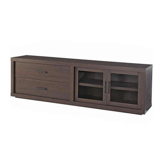
Steele TV Stand
Stock # BH46-084-899-02
ADULT ASSEMBLY REQUIRED
www.whalenstyle.com
Or e-mail your request to parts@whalenfurniture.com
PLEASE READ AND KEEP FOR FUTURE REFERENCE.
Date 2016-05-05 Rev. 0001-A Factory: KONRIC
866-942-5362
LOT NUMBER:
DATE PURCHASED: /
/
Advertisement
Table of Contents

Related Manuals for Better Homes and Gardens BH46-084-899-02


Summary of Contents for Better Homes and Gardens BH46-084-899-02
- Page 1 LOT NUMBER: DATE PURCHASED: / Steele TV Stand Stock # BH46-084-899-02 ADULT ASSEMBLY REQUIRED If you have any questions regarding assembly or if parts are missing, DO NOT return this item to the store where it was purchased. Please call our customer service number and have your instructions...
- Page 2 M A X I M U M R E C O M M E N D E D W E I G H T L O A D S MANUFACTURER: Whalen Furniture Manufacturing CATALOG: Steele TV Stand (BH46-084-899-02) MADE IN CHINA FITS UP TO MOST 80”...
- Page 3 Important Before you begin: Open, identify and count all parts prior to assembly. Lay out parts on a flat and non- abrasive surface. You will need the parts identified on page 4 and 5 of this instruction manual. NOTE: IT IS VERY IMPORTANT TO USE GLUE WITH DOWELS. EXCESS GLUE CAN BE WIPED OFF WITH DAMP CLOTH.
- Page 4 Parts and Hardware List Please read completely through the instructions and verify that all listed parts and hardware are present before beginning assembly. A- Top Panel (Qty. 1) B- Bottom Panel (Qty. 1) C- Base Front Stretcher (Qty. 1) D- Base Back Stretcher (Qty. 1) E- Base Side Stretcher (Qty.
- Page 5 Parts and Hardware List Please read completely through the instructions and verify that all listed parts and hardware are present before beginning assembly. (1) Small Cam Lock (2) Large Cam Lock (3) Cam Bolt (Qty. 10+1 extra) (Qty. 12+1 extra) (Qty.
- Page 6 Drawer Assembling M6 x 30 mm Wood Dowel M4 x 38 mm Screw (4 used in this step) (4 used in this step) ④ ⑦ 1. Unpack the unit and confirm that you have all the hardware and required parts. Assemble the unit on a carpeted floor or the empty carton to avoid any scratch.
- Page 7 Drawer Assembling 4. Slide the Drawer Bottom Panel (R) into the grooves between the Drawer Side Panels (O and P) until fully inserted into the Drawer Front (N).
- Page 8 Drawer Assembling M6 x 30 mm Wood Dowel (1 used in this step) ④ 5. Glue one M6 x 30 mm Wood Dowel (4) into the back center hole of the Drawer Bottom Support (Q) and attach it to the Drawer Back Panel (N).
- Page 9 Drawer Assembling Cam Bolt Small Cam Lock M6 x 30 mm Wood Dowel (5 used in this step) (5 used in this step) (6 used in this step) ③ ① ④ 6. Securely screw five Cam Bolts (3) into the designated small holes on the Drawer Front Panel (M) as shown.
- Page 10 Drawer Assembling M4 x 38 mm Screw (2 used in this step) ⑦ 8. Fasten the Drawer Back Panel (N) to the Drawer Bottom Support (Q) with two 38 mm Screws (7) using a Phillips screwdriver.
- Page 11 Drawer Assembling Handle Handle Bolt (1 used in this step) (2 used in this step) ⑮ ⑭ 9. Attach one Drawer Handle (14) to the outside of Drawer Front (M) using two provided Handle Bolts (15). 10. Repeat the same procedure to assemble the other drawer.
- Page 12 Assembly Instructions Corner Connector (4 used in this step) ⑪ M8 x 30 mm Wood Dowel (8 used in this step) ⑤ 15 mm Washer Head Screw (8 used in this step) ⑥ 11. Attach two Base Side Stretchers (E) between the Front and Back Stretchers (C and D) with eight Wood Dowels (5).
- Page 13 Assembly Instructions M3.5 x 12 mm Screw Triangle Metal Plate (8 used in this step) (2 used in this step) ⑯ ⑰ 13. Using the pilot holes as a guide, fasten two Triangle Metal Plates (17) at the bottom joints between Front Bottom Stretcher (C) and Side Stretchers (E) using four 12 mm Screws (16) per plate.
- Page 14 Assembly Instructions Floor Leveler (2 used in this step) ⑱ 14. Tightly screw two Floor Levelers (18) into the Triangle Metal Plates (17) and set to the correct height.
- Page 15 Assembly Instructions C/D/E M8 x 30 mm Wood Dowel M4 x 50 mm Screw (10 used in this step) (12 used in this step) ⑤ ⑧ 15. Glue ten M8 x 30 mm Wood Dowel (5) into the inner holes of the Bottom Panel (B). 16.
- Page 16 Assembly Instructions Cam Bolt (6 used in this step) ③ 17. Securely screw the Cam Bolts (3) into the designated small holes on the Bottom Panel (B) using a Phillips screwdriver.
- Page 17 Assembly Instructions Cam Bolt M3 x 15 mm Pan Head Screw Magnetic Catch (6 used in this step) (4 used in this step) (2 used in this step) ③ ⑨ ⑩ 18. Securely screw six Cam Bolts (3) into the designated small holes on the Top Panel (A) using a Phillips screwdriver.
- Page 18 Assembly Instructions Large Cam Lock M10 x 40 mm Wood Dowel (12 used in this step) (12 used in this step) ⑲ ② 20. Glue twelve Wood Dowels (19) into the inner end holes of vertical panels (F, G and H) at both ends. 21.
- Page 19 Assembly Instructions 15 mm Washer Head Screw (40 used in this step) ⑥ 22. Now, go back and tighten all Cam Locks and Screws. Make sure that all the parts are tight and there are no gaps between the pieces. This will help keep the unit square. 23.
- Page 20 Assembly Instructions Shelf Pin Cam Lock Cover (4 used in this step) (4 used in this step) ⑫ ⑬ 24. Stand the unit upright. 25. Insert four Shelf Pins (12) into the holes at your desired height inside right compartment. Tilt and rest the Adjustable Shelf (K) onto the Shelf Pins (12).
- Page 21 Assembly Instructions Handle Handle Bolt (2 used in this step) (4 used in this step) ⑮ ⑭ 27. Attach one Handle (14) to the front side of each Door (I and J) with the provided Handle Bolts (15). 28. Pick up Left Door (I) and attach the extended Hinge Arms to the Hinge Bases installed on the Partition Panel (G).
- Page 22 Assembly Instructions 31. Extend the Sliding Tracks on the Panels (F and G) all the way forward (including ball bearing cart). Then align the Slide Runners on the assembled drawers with the Slide Tracks and push the drawers carefully inside until it stops. NOTE: If the drawer does not go in smoothly, please take it out and repeat the step.
- Page 23 Assembly Instructions Tools required: Phillips screwdriver, Power Drill, 3/8” Drill Bit and Rubber Mallet. 32. Ask for assistance to position the assemble TV stand at the desired location against a wall. If necessary, adjust the installed Floor Levelers (18) at the bottom of the Base to level the unit. Now, follow the instructions printed on the plastic bag containing the Tipping Restraint Hardware to attach the tip-over restraints to the unit and the wall.
-
Page 24: Care And Maintenance
Care and Maintenance Use a soft, clean cloth that will not scratch the surface when dusting. Use of furniture polish is not necessary. Should you choose to use polish, test first in an inconspicuous area. Using solvents of any kind on your furniture may damage your furniture’s finish. Never use water to clean your furniture as it may cause damage to the finish.
Need help?
Do you have a question about the BH46-084-899-02 and is the answer not in the manual?
Questions and answers