Table of Contents
Advertisement
Available languages
Available languages
Quick Links
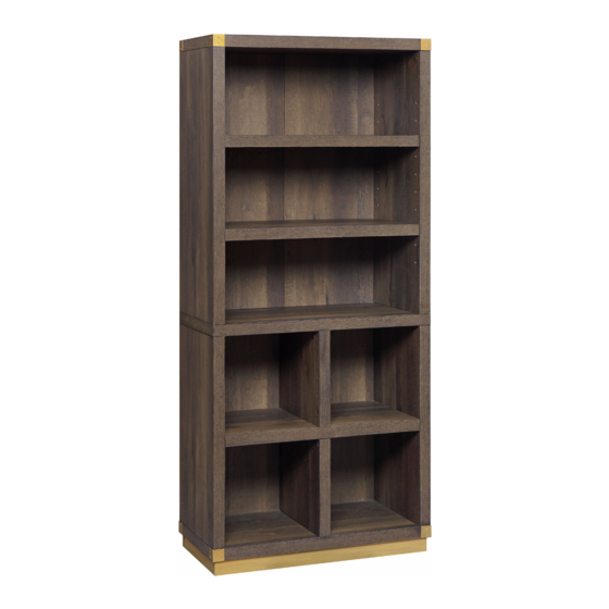
Lana Modern Cube Bookcase
If you have any questions regarding assembly or if parts are missing, DO NOT return this item to
the store where it was purchased. Please call our customer service number and have your
instructions and parts list ready to provide the model name, part name or factory number:
Pacific Standard Time: 8:30 a.m. - 4:30 p.m., Monday - Friday
Or visit our web site 24 hours a day, 7 days a week for product assistance at
THIS INSTRUCTION BOOKLET CONTAINS IMPORTANT SAFETY INFORMATION.
Stock # BH48-084-099-05
ADULT ASSEMBLY REQUIRED
www.whalenstyle.com
Or e-mail your request to parts@whalenfurniture.com
PLEASE READ AND KEEP FOR FUTURE REFERENCE.
Date 2018-06-30 Rev. 0001-A Factory: HESLTD
866-942-5362
LOT NUMBER:
DATE PURCHASED:
/
/
Advertisement
Table of Contents

Related Manuals for Better Homes and Gardens Lana Modern Cube Bookcase


Summary of Contents for Better Homes and Gardens Lana Modern Cube Bookcase
- Page 1 LOT NUMBER: DATE PURCHASED: Lana Modern Cube Bookcase Stock # BH48-084-099-05 ADULT ASSEMBLY REQUIRED If you have any questions regarding assembly or if parts are missing, DO NOT return this item to the store where it was purchased. Please call our customer service number and have your...
- Page 2 M A X I M U M R E C O M M E N D E D W E I G H T L O A D S MANUFACTURER: Whalen Furniture Manufacturing CATALOG: Lana Modern Cube Bookcase MODEL # BH48-084-099-05 MADE IN CHINA MAXIMUM LOAD 50 lb.
- Page 3 IMPORTANT Before you begin: Open, identify and count all parts prior to assembly. Lay out parts on a flat and non- abrasive surface. You will need the parts identified on page 4 and 5 of this instruction manual. NOTE: IT IS VERY IMPORTANT TO USE GLUE WITH DOWELS. EXCESS GLUE CAN BE WIPED OFF WITH DAMP CLOTH.
- Page 4 Parts and Hardware List Please read completely through the instructions and verify that all listed parts and hardware are present before beginning assembly. A- Left Upper Side Panel B- Right Upper Side Panel C- Left Lower Side Panel (Qty. 1) (Qty.
- Page 5 Parts and Hardware List Please read completely through the instructions and verify that all listed parts and hardware are present before beginning assembly. (1) Cam Lock (2) Cam Bolt (3) M15 x 60 mm Wood Dowel (Qty. 30+1 extra) (Qty. 30+1 extra) (Qty.
- Page 6 Assembly Instructions Cam Bolt (16 used in this step) ② 1. Unpack the unit and confirm that you have all the hardware and required parts. Assemble the unit on a carpeted floor or the empty carton to avoid any scratch. 2.
- Page 7 Assembly Instructions Cam Lock M15 x 60 mm Wood Dowel (4 used in this step) (4 used in this step) ③ ① 3. Insert four 60 mm Wood Dowels (3) into the inner holes on the Top Panel (E) as a guide. Tap it in with a rubber mallet, if necessary.
- Page 8 Assembly Instructions M4 x 50 mm Screw M15 x 60 mm Wood Dowel (4 used in this step) (4 used in this step) ③ ⑥ 5. Attach the Upper Fixed Shelf (F) to the bottom of Upper Side Panels (A and B) with four 60 mm Wood Dowels (3) and four 50 mm Screws (6).
- Page 9 Assembly Instructions M4 x 50 mm Screw M15 x 60 mm Wood Dowel (2 used in this step) (2 used in this step) ③ ⑥ 6. Attach one Partition Panel (G) to the Lower Fixed Shelf (H) with two 60 mm Wood Dowels (3) and two 50 mm Screws (6).
- Page 10 Assembly Instructions Cam Lock M15 x 60 mm Wood Dowel (6 used in this step) (6 used in this step) ③ ① 7. Attach the other Partition Panel (G) to the Lower Fixed Shelf (H) at the opposite side with two 60 mm Wood Dowels (3) and two Cam Locks (1).
- Page 11 Assembly Instructions Cam Bolt (14 used in this step) ② 9. Securely screw the Cam Bolts (2) into the designated small holes on the Bottom Panel (I) and the Base Long Stretchers (K) with a Phillips screwdriver.
- Page 12 Assembly Instructions M4 x 50 mm Screw M15 x 60 mm Wood Dowel (6 used in this step) (6 used in this step) ③ ⑥ 10. Attach the Bottom Panel (I) to the bottom of both Lower Side Panels (C and D) and the Partition Panel (G) with six 60 mm Wood Dowels (3) and six 50 mm Screws (6).
- Page 13 Assembly Instructions Cam Lock M15 x 60 mm Wood Dowel (6 used in this step) (6 used in this step) ③ ① 11. Attach the assembled upper fixed shelf (F) to the top of the vertical panels (C, D and G) with six 60 mm Wood Dowels (3) and six Cam Locks (1).
- Page 14 Assembly Instructions Cam Lock (4 used in this step) ① 12. Attach the Base Short Stretchers (L) between the Base Long Stretchers (K) with four Cam Locks (1).
- Page 15 Assembly Instructions M8 x 30 mm Wood Dowel Cam Lock (8 used in this step) (10 used in this step) ④ ① 13. Attach the assembled base to the Bottom Panel (I) with eight 30 mm Wood Dowels (4) and ten Cam Locks (1).
- Page 16 Assembly Instructions M3.5 x 15 mm Washer Head Screw (44 used in this step) ⑦ 14. Now, go back and securely tighten all the cam locks and the screws. Make sure that all the parts are tight and there are no gaps between the parts. This will help keep the unit square. 15.
- Page 17 Assembly Instructions Cam Lock Cap (16 used in this step) ⑧ 16. Ask for assistance to stand the unit upright and position at the desired location. 17. Put the Cam Lock Caps (8) onto the visible Cams Locks to conceal the cams.
- Page 18 Assembly Instructions Shelf Pin (8 used in this step) ⑤ 18. Insert the Shelf Pins (5) into the desired holes on the Upper Side Panels (A and B). Make sure that you place the four Shelf Pins (5) at the same level so the shelf is not tilted. 19.
- Page 19 Assembly Instructions Tools required (not provided): Phillips screwdriver, stud finder, power drill and 3 mm/0.1 in drill bit. 20. Ask for assistance to position the unit at the desired location against a wall. 21. Follow the instructions printed on the plastic bag containing the Tipping Restraint Hardware to attach the tip-over restraints to the unit and the wall.
-
Page 20: Care And Maintenance
Care and Maintenance Use a soft, clean cloth that will not scratch the surface when dusting. Use of furniture polish is not necessary. Should you choose to use polish, test first in an inconspicuous area. Using solvents of any kind on your furniture may damage the finish. ... - Page 21 NÚMERO DEL LOTE: FECHA DE COMPRA Moderna Estantería Cúbica Lana Serie # BH48-084-099-05 ENSAMBLE REQUERIDO POR ADULTO Si tienen alguna pregunta acerca del ensamble o si alguna parte está faltante, no retorne esté producto a la tienda donde lo compró. Por favor llame a nuestro departamento de ayuda al cliente teniendo su instructivo y lista de partes para proveer el modelo, nombre de parte o el número de fábrica : 866-942-5362...
- Page 22 M Á X I M O P E S O R E C O M E N D A D O FABRICANTE: Whalen Furniture Manufacturing CATALOGO: Moderna Estantería Cúbica Lana MODELO # BH48-084-099-05 HECHO EN CHINA CARGA MÁXIMA 50 lb. (22.7 kg) CARGA MÁXIMA 30 lb.
- Page 23 IMPORTANTE Antes de comenzar: Abra, identifique y cuente todas las partes antes del ensamble. Coloque las piezas sobre una superficie plana y no abrasiva. Tendrá que las partes identificadas en la página 4 y 5 de este manual de instrucciones. NOTA: ES MUY IMPORTANTE PARA EL USO DE GOMA CON LOS PERNSO DE MADERA.
- Page 24 Lista de partes y material de ferretería Le rogamos que lea completamente las instrucciones y verifique que todas las piezas y ferretería indicadas se encuentran presentes antes del comienzo del montaje. A- Módulo lateral B- Módulo lateral C- Módulo lateral superior izquierdo superior derecho inferior izquierdo...
- Page 25 Lista de partes y material de ferretería Le rogamos que lea completamente las instrucciones y verifique que todas las piezas y ferretería indicadas se encuentran presentes antes del comienzo del montaje. (1) Tuerca de fijación (2) Perno de fijación (3) M15 x 60 mm Espiga de madera (Cant.
- Page 26 Instrucciones de ensamble Perno de fijación (16 usados en este paso) ② 1. Desembale la unidad y confirme que cuenta con todo el equipo y partes necesarias. Monte la unidad sobre un suelo con alfombra o el cartón de embalaje vacío para evitar cualquier arañazo. 2.
- Page 27 Instrucciones de ensamble Tuerca de fijación M15 x 60 mm Espiga de madera (4 usados en este paso) (4 usados en este paso) ③ ① 3. Introduzca cuatro espigas de madera de 60 mm (3) en los agujeros interiores del módulo superior (E) como guía.
- Page 28 Instrucciones de ensamble M4 x 50 mm Tornillo M15 x 60 mm Espiga de madera (4 usados en este paso) (4 usados en este paso) ③ ⑥ 5. Fije la balda fija superior (F) a los módulos laterales superiores (A y B) con cuatro espigas de madera de 60 mm (3) y cuatro tornillos de 50 mm (6).
- Page 29 Instrucciones de ensamble M4 x 50 mm Tornillo M15 x 60 mm Espiga de madera (2 usados en este paso) (2 usados en este paso) ③ ⑥ 6. Fije el módulo divisor (G) a la balda fija inferior (H) con dos espigas de madera de 60 mm (3) y dos tornillos de 50 mm (6).
- Page 30 Instrucciones de ensamble Tuerca de fijación M15 x 60 mm Espiga de madera (6 usados en este paso) (6 usados en este paso) ① ③ 7. Fije el otro módulo divisor (G) a la balda fija inferior (H) en el lado opuesto con dos espigas de madera de 60 mm (3) y dos tuercas de fijación (1).
- Page 31 Instrucciones de ensamble Perno de fijación (14 usados en este paso) ② 9. Fije firmemente los pernos de fijación (2) en los pequeños agujeros designados en el módulo inferior (I) y a los bastidores largos de la base (K) con un desarmador estrella.
- Page 32 Instrucciones de ensamble M4 x 50 mm Tornillo M15 x 60 mm Espiga de madera (6 usados en este paso) (6 usados en este paso) ③ ⑥ 10. Fije el módulo inferior (I) a los módulos laterales inferiores (C y D) y el módulo divisor (G) con seis espigas de madera de 60 mm (3) y seis tornillos de 50 mm (6).
- Page 33 Instrucciones de ensamble Tuerca de fijación M15 x 60 mm Espiga de madera (6 usados en este paso) (6 usados en este paso) ③ ① 11. Fije la balda fija superior ya montada (F) a la parte superior de los módulos verticales (C, D y G) con seis espigas de madera de 60 mm (3) y seis tuercas de fijación (1).
- Page 34 Instrucciones de ensamble Tuerca de fijación (4 usados en este paso) ① 12. Una los bastidores cortos de la base (L) entre los bastidores largos de la base (K) con cuatro tuercas de fijación (1).
- Page 35 Instrucciones de ensamble M8 x 30 mm Espiga de madera Tuerca de fijación (8 usados en este paso) (10 usados en este paso) ④ ① 13. Una los bastidores de la base ya montados al módulo inferior (I) con ocho espigas de madera de 30 mm (4) y diez tuercas de fijación (1).
- Page 36 Instrucciones de ensamble M3.5 x 15 mm Tornillos con arandela (44 usados en este paso) ⑦ 14. Ahora volver y apretar todas las tuercas de fijación y tornillos, asegurar que todas las partes esten apretadas y de que no hay huecos entre las partes, esto ayudara a mantener la unidad cuadrada. 15.
- Page 37 Instrucciones de ensamble Tapa de la tuerca de fijación (16 usados en este paso) ⑧ 16. Pida ayuda para levantar la unidad y situarla en el lugar deseado. 17. Coloque las tapas de las tuercas de fijación (8) en las tuercas visibles para esconder.
- Page 38 Instrucciones de ensamble Clavija de la balda (8 usados en este paso) ⑤ 18. Inserte las clavijas de la balda (5) en los agujeros de los módulos laterales superiores (A y B). Asegurar de poner 4 clavijas de la balda en el mismo nivel para que la baldaa no se incline. 19.
- Page 39 Instrucciones de ensamble (no incluidas): Desarmador estrella, buscador de estudios, Herramientas adicionales requeridas taladro y broca de 3 mm/0.1 pulgada. 20. Pedir asistencia para posicionar la unidad ensamblada en posición vertical y en el lugar deseado contra la pared. 21. Seguir las instrucciones impresas en la bolsa de plástico que contiene el juego de restricción de movimiento para adjuntar los topes de movimiento a la unidad y pared.
- Page 40 Mantenimiento y Cuidados Use una toalla suave y limpia para evitar daños y rayones. Uso de cera para pulir muebles no es necesario. Si desea usar cera, pruébela en un área que no sea visible para revisar su funcionamiento. ...
Need help?
Do you have a question about the Lana Modern Cube Bookcase and is the answer not in the manual?
Questions and answers