Table of Contents
Advertisement
Quick Links
Advertisement
Table of Contents

Subscribe to Our Youtube Channel
Related Manuals for Dantherm 3500


Summary of Contents for Dantherm 3500
- Page 1 DC Split Air Conditioner 3500 Installation manual Rev. 1.0...
-
Page 2: Table Of Contents
Introduction Introduction! This is the Installation manual for the Dantherm DC Split Air Conditioner 3500. Please see the below table of content for further information about the sections. Target group The target group for this service manual are the technicians who install and maintain the DC Split Air conditioner 3500 unit, as well as the users of the unit. - Page 3 This section describes the overall product, and its functionality Usage of the DC Split The DC Split Air conditioner 3500 is designed to control the internal temperature of an Air conditioner 3500 outdoor enclosure. The DC Split Air conditioner 3500 removes dissipated heat from electronic equipment and it´s designed to maintain correct temperature for electronic equipment.
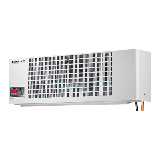
- Page 4 Product description, continued Indoor unit This illustrates visible parts of the indoor unit. Air inlet Controller • Adjust setting Louvers • SD card TTL link Change of air direction • RS 485 Modbus Air outlet • Alarm output • A/C connect •...
- Page 5 Product description, continued Outdoor unit This illustrates the visible parts of the outdoor units Top Service Cover Condenser Air Outlet Unit support Bracket Connection for Fan Air hose and power Inlet cable. Parts description The outdoor unit contains the condenser coil, condenser fan, compressor, compressor drive outdoor unit and 48VDC Power input for the entire unit.
-
Page 6: Accessories
Dantherm Air Handling A/S. DATE: 04-10-16 All designs originated by Dantherm Air Handling A/S are the property of said Company and will be protected by Patents. PART NO REV.: Boxed kit with fixings. -
Page 7: Installation
Clamp for drainage hose Manual Part number: 095106 Parts needed for installation There might be need for further installations parts whicha are not supplied with the Dantherm DC Split Air Condition 3500. • Any screws for mounting indoor and outdoor unit •... -
Page 8: Safety Precautions
To prevent the injury of user or other people and property damage, the following in-structions must be followed • Be sure to read before installing the DC Split Air Condition 3500 • Be sure to observe the cautions specified here as they include important safety related issues •... - Page 9 Installation of indoor, outdoor unit Select the best location To ensure maximum effieciency mount the indoor unit near but not too close to the ceiling. Secure the unit in a manner so there is ample room for maintenance and service after installation.
- Page 10 Installation of indoor, outdoor unit, continued The outdoor unit can´t be installed further from the indoor unit than the enclosed cables and copper tubes can be used without any extensions. The length is 3,5m. This is easily obtained by installing the indoor unit near the ceiling and the outdoor unit on the other side of the wall near the ground.
- Page 11 The piping between the indoor and the outdoor unit is not included in the DC Spilt Ari indoor and outdoor unit Conditioner 3500. It can be provided from Dantherm or it can be prepared by the installer. Dantherm can provide prepared piping sets at 3, 5 or 10 meters.
- Page 12 Installation of indoor, outdoor unit, continued Connecting the piping Find the two insulated rubber hoses and connect the flares to the indoor Unit. Align the Center of the pipe/hose and tighten the flare nut by hand And then tighten the flare nut with a wrench 9-pin connector 12-pin connector Liquid line 3/8"...
- Page 13 Installation of indoor, outdoor unit, continued Wall hole for piping and drain Drill a Ø85 hole through the wall for piping, cabling and drain hose, See sketch below Outside Inside Secure the hole with a plastic sleeve in order to avoid sharp edges, this can also be done with heavy duty tape Mount indoor unit Place the indoor unit on the hooks of the wall bracket, and secure the unit with two screws at...
- Page 14 Installation of indoor, outdoor unit, continued Cables and flares Put the the two cables through the hole in the wall. Next pull the cooling pipes and drainage from inside through the hole in the wall. Do not bend or block the drain hose. Be careful not to make a sharp bend at the refrigerant pipes.
- Page 15 Installation of indoor, outdoor unit, continued Electrical installation Plug the communication cable into the plug on the right side of the indoor unit 9-pin connector 12-pin connector Liquid line 3/8" Flare Screw this on shielded cable Grounding The communication cable is a shielded cable and needs a secure grounding at the indoor unit, use the metal cable tie at the indoor unit to make that grounding Connect the Power cable + and –...
- Page 16 Leakage test Leakage Test The Outdoor unit is filled with refrigerant R134a for the whole system. This unit is hermetically sealed. The only access is through the two service valves located on the side of the unit. The indoor unit and the piping is open and the connections need to be checked for leakage . Check that each tube-both liquid and gas side tubes have been properly connected.
- Page 17 Replace the valve caps at both gas and liquid side service port and fasten them tightly This completes air purging with the vacuum pump and fill the whole system with refrigerant. The DC split Air condition 3500 is now ready for its´ first test run.
-
Page 18: Operation
Operation The adaptive cooling strategy guarantees the lowest power consumption at all time during operation. Reduces wear and tear of cooling system, and lowers acoustical noise level. • SD card* socket for data logging and configuration. • RS 485 RTU ModBus*. (Monitoring and remote user panel) •... - Page 19 Operation, continued Menu structure and navigation. Step up Step down Enter Step up/down to jump through menues, end. Enter to select the parameter to read or change Step Action Display Hibernate mode shows the actual room tempereature. After 3 minutes without activity on the keys, the controller exits any menu and shows this.
-
Page 20: Error List
Error list If any failure happens at the cooling mode an error code will show in the display. The error - Exx and the corresponding corrective action can be found in the table below. Display error No. Error description What to do The supply voltage is higher than the pre-set Check the rectifier and adjust the supply 60VDC, and the Controller stop the unit. -
Page 21: Connections
Connections Front of CC0: Step up Enter Step down Name Description Dry contact NC, can be changed to NO in the Alarm 1 configuration file and uploaded to CC0 via SD card. Jumper on PCB for change of NO/NC relay contact. Alarm 1 Max voltage 60V DC/100mA. -
Page 22: Modifying The Configuration File
Modifying the Configuration file How to set up fire/ smoke Connect the smoke detector to the digital input 1. alarm: Ensure that the smoke detector has a dry contact. If there is voltage at the digital input, the CC0 controller will be damaged. When the smoke detector gives input the DC Air Conditioner will stop Digital 1 and 2 is pre-set to NO, but can be changed to NC. - Page 23 [0/1]: Change the marked value in line 1 and 2 to the values you want. There is a possibility to run lead lag with the DC Split Air Conditioner 3500 and an Extern A/C unit. Leadlag means that either the DC Split Air Conditioner 3500 or an external A/C starts everytime there is a cooling requirement.
- Page 24 DC Split Air Conditioner 3500 connected to a Free Cooling unit for example Dantherm Flexibox 900. See below: Two DC Split air Conditioner When two DC Split Air condition 3500 are connected one is master and the other one should be 3500 in same room set in cooling on demand (slave) connected Connect A/C output from DC Air Condition to digital 2 input at the other DC Split Air conditioner 3500 (slave).
- Page 25 Test Mode Via onboard navigation keys and display, test mode can be initiated. Can be used for service purpose, and fault finding. Press up/down key, until test is visible in display. Now press enter. Controller will now automatically go through pre-defined test steps, or up/down key can be used for manually selection of test step.
-
Page 26: Electrical Schematic
Electrical schematic - Outdoor unit Electrical schematic Outdoor Unit... - Page 27 Electrical schematic - Indoor unit Electrical schematic Indoor Unit...
- Page 28 Connections Outdoor side To indoor Pin No: Colour Pin No: Connector Connectors to In-rush filter Black 1 and Compressor Drive Black 2 Fan 1 Inrush filter Black 3 Black 4 9 Pins Black 5 Condenser sensor Black 6 Black 7 Black 8 Internal Fan Inrush filter...
- Page 29 Connections, continued Indoor side Connection from To indoor Pin No: Colour Pin No: Connector Description outdoor unit Yellow Internal fan White Blue Temp Black Return sensor sensor 9 Pins Black Black Condenser temp. Brown Orange Fan1 Yellow Green Blue Violet Fan 2 Gray White...
-
Page 30: Cooling Circuit
Cooling circuit Introduction This section describes the active cooling system WARNING Before any installation, maintenance or service, disconnect the DC power supply by disconnecting devices from external power supply. Service on any cooling circuit with cooling refrigerant is only to be carried out by a trained cooling technician. - Page 31 Technical data Product overview Category DC Air Conditioning DC Split Air Conditioner 3500 364000 Dantherm No. Capacity & Performance °C -15 to +55 Operating range - temperature 3624 Cooling capacity at 35°C internal and 35°C ambient 3822 Cooling capacity at 35°C internal and 25°C ambient Efficiency ratio at 35°C internal and 35°C ambient...
- Page 32 Technical data, continued Dimensions Outdoor Unit Indoor Unit...
-
Page 33: Spare Parts
Capacitor 2200μF / 100V 087956 Low pressure switch, DC Split Air Con 3500 096454 DC Inrush Filter , DC Split Air Conditioner 3500 096457 Condenser Fan DC Split Air Con 3500 094655 Dryfilter, DCL 053S, DC Split Air Con 3500... - Page 34 Internal Fan DC Split Air Con 3500 Declaration of Conformity Declaration of Conformity Dantherm Air Handling A/S, Marienlystvej 65, DK-7800 Skive hereby declare that the units DC Split Air Conditioner 3500 is in conformity with the following directives: 2006/42/EC Directive on the Safety of Machines...
- Page 36 Dantherm n’assume aucune responsabilité pour erreurs et modifications éventuelles. Dantherm se exime de cualquier responsabilidad por errores y cambios realizados. A Dantherm recusa qualquer responsabilidade relacionada com eventuais erros e alterações. Компания Dantherm не принимает на себя ответственность за возможные ошибки и изменения в настоящем документе.
Need help?
Do you have a question about the 3500 and is the answer not in the manual?
Questions and answers