Table of Contents
Advertisement
Quick Links
Advertisement
Table of Contents

Subscribe to Our Youtube Channel
Related Manuals for Dantherm AC-24


Summary of Contents for Dantherm AC-24
- Page 1 SERVICE MANUAL AC-24 en • Rev. 1.2.1 • 2020-W48-3...
- Page 3 Declaration of Conformity Dehumidification Dantherm S.p.A Marienlystvej 65 DK - 7800 Skive Tel.: +45 96 14 37 00 Fax: +45 96 14 38 00 Declaration of following product: Product name: AC 24 Product no.: 323043 The product is in conformity with the following directives:...
- Page 4 Overview Introduction This is the service manual for the Dantherm A/S AC-24 unit. The below table of contents gives an overview of the main sections. This manual is for the unit AC 24 Dantherm Number Code 323043 AC-24-B-305-R9010 * 4120-22-631-1514 *) The code is specified on the data plate, which is placed on the control panel.
- Page 5 Copying of this service manual, or part of it, is forbidden without prior written permission from Dantherm A/S. Reservations Dantherm A/S reserves the right to make changes and improvements to the product and the service manual at any time without prior notice or obligation. Recycling The unit is designed to last for many years.
-
Page 6: Table Of Contents
Table of contents Table of content Product description See page General description Transport of the unit Description of parts Syntax Description of the cooling system Description of the control board Description of room thermostat Description of the high and low pressure switch function Functional Description User´s guide Preparations... - Page 7 Product description Introduction This section will give you a description of the AC 24 and its functionality. Content The section covers the following topics: Topic See page General description Transport of the unit Description of parts Syntax Description of the cooling system Description of the control board Description of room thermostat Description of the high and low pressure switch function...
-
Page 8: General Description
General description Introduction This section describes the unit as a whole. The following sections describe the different parts of the unit.. General The AC 24 is a portable air conditioner that is made of high quality materials and the production process is subject to constant quality checking. The instructions in this service manual have been prepared to ensure that, when followed, this air condi-tioner will provide long and efficient service. -
Page 9: Transport Of The Unit
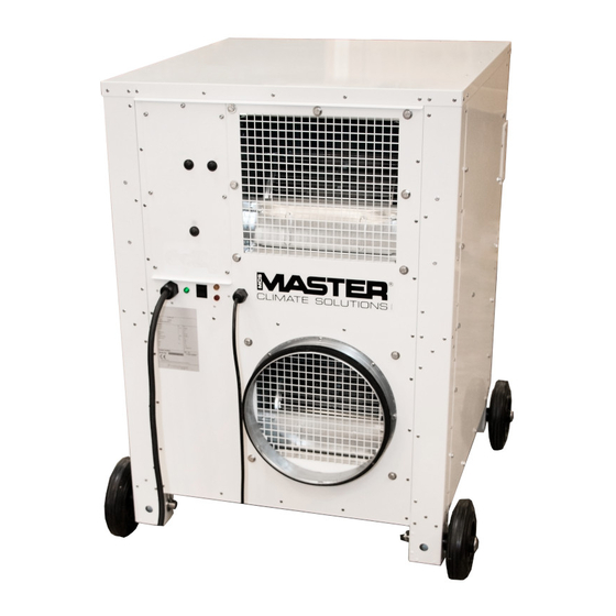
General description, continued Illustration This illustration gives an overview of the unit. Parts Item Description Handlebars for transport ( Accessories) Wheels for easy field mobility of the unit (Accessories) Control panel with function switch and lamps Mains cable Room thermostat Transport of the... - Page 10 Syntax Introduction All products are named according to a syntax giving information about the specific unit configuration. Example This example is not necessarily related to the specific unit this manual describes: AC _24_B _305_R9010 Air conditioner Nominal performance 24.000BTU/h 1ph; 230VAC; 50Hz 1ph;...
-
Page 11: Description Of Parts
Description of parts Introduction This section gives a description of the following parts of the AC 24: • Cabinet • Fans • Air filters • Mains cable • Heating coil • Air openings The following sections in this chapter give separate detailed descriptions of the cooling circuit, the control board and operation. - Page 12 Description of parts, continued Mains cable The unit requires an external electric power source. The mains cable is 10 m long and normally has a 16 A CEE connector at its end. Air openings Varm air outlet Cold air intake Cold air out Hot Air intake...
- Page 13 Description of parts, continued Air openings, continued inlets/outlets Purpose Supply air outlet, Air is supplied to the tent/shelter through these openings. 1 × 315 mm Flexible air hose(s) will be connected here Return air inlet, Air is drawn into the unit through this/these opening(s).
-
Page 14: Description Of The Cooling System
Description of the cooling system Illustration This drawing illustrates the different parts of the cooling circuit and where they are situated in the AC 24 unit: Parts and their function This table gives an overview and short description of each part shown above and on the next page: ... - Page 15 Description of the cooling system, continued Description Both evaporator and condenser are heat exchangers with copper tubes and aluminium coated fins. By the cooling of the evaporator air stream heat is adapted to the cooling circuit and released in the condenser together with the electric energy consumption of the compressor. At room temperatures below 20 °C, where cooling is not normally required, the humidity in the airflow will form ice on the evaporator.
-
Page 16: Description Of The Control Board
Description of the control board Introduction This section gives a description of the control board. A description of how to start up, for example, is found in the relevant sections. The control panel on the front contains the controls required for normal operation. Illustration This drawing illustrates the control board of the AC 24: See references on next page. - Page 17 Description of the control board, continued Part/function This table gives an overview of each part of the control panel in fig. 6: Part Function Electric Mains cable with a 16 A CEE connector at the end connection Function The function switch selects the operating mode and has three ...
-
Page 18: Description Of Room Thermostat
Description of room thermostat Introduction This section gives a description of the room thermostat. Illustration This drawing illustrates the different parts of the room thermostat: For instructions on how to operate the thermostat controller, see page 23 Parts and their function No Part Function... -
Page 19: Description Of The High And Low Pressure Switch Function
Description of the high and low pressure switch function Introduction This topic describes the HP/LP function. System protection The cooling system is protected by pressure switches. If the pressure falls outside of the normal operating range, the air conditioner compressor is automatically switched off. This is to prevent component damage. -
Page 20: Functional Description
Functional description VENT With the function switch in this position the evaporator fan will operate continuously and Ventilation-only the cooling unit, heating coil (if installed) and condenser fan will be turned off. operation This mode can be used to bring in fresh outdoor air or to recirculate the indoor air - even when cooling or heating (if installed) is not needed. -
Page 21: User's Guide
User’s guide Introduction This section describes how to utilise the different functions. WARNING Do not try to restart the compressor several times within a short period. This will make the compressor overheat and may damage it. The internal compressor thermostatic protection may also cut out. Operating the product outside the temperature range specified in the technical data will cause the cooling system to start frequently. - Page 22 Preparations Location Follow these conditions when siting the air conditioner: Conditions Place in the shade as close as possible to the tent/shelter that needs to be ventilated Place the air supply ducts in both ends of the tent/shelter Allow sufficient space around the air conditioner for operating and servicing access Avoid sharp bends or kinking when locating air supply ducts in order to avoid disrup-tion of the airflow (see “Recommended camp configuration”, page 24) Keep any source of engine exhaust fumes (vehicles/generators etc.) away from air in-takes...
-
Page 23: Setup
Setup Procedure Step Action Find a suitable location for the air conditioner as described on previous page. Supply ducts. Connect the flexible air hoses to the evaporator discharge openings ( Cold air out) and insert the opposite end of the hose to the tent. If there are any internal distribution hoses in the tent, these can also be connected. -
Page 24: Operating The Room Thermostat
Press and hold both buttons when powering up the unit. FACTORY RESET (FAC is displayed) Note: Above mentioned factory reset does only apply on units with serial numbers after 1810000000000. Contact Dantherm for thermostat controller factory settings for units with serial numbers below 1810000000000. -
Page 25: Recommended Camp Configuration
Recommended camp configuration Introduction The configuration is an important factor for gaining the highest performance and reliability from the air conditioner including lowest power consumption. A camp can be set up in various ways and still work, but a few important hints will be given in this section. This section describes the following: •... - Page 26 Recommended camp configuration, continued Air distribution In cases where air distribution plenums are used for distributing the internal cooled air, it can be an advantage if the plenum is located under the roof. The cold air will slowly fall to ground and be sucked back into the air conditioner. Without return air With return air Sand storm...
- Page 27 If possible raise the air conditioner above ground level by use of a pallet or other suitable means. WARNING Do not park vehicles where exhaust gases can be drawn into the air intake of the AC-24...
-
Page 28: Starting Up And Shutting Down The Air Conditioner
Starting up and shutting down the air conditioner Start up After preparation and set-up the air conditioner is ready for operation. Turn the function switch to the desired mode (see “Description of the control board”, page 15) and the unit will operate according to the “Functional description”, Fault If the unit does not operate it might have been switched off by a safety device: •... -
Page 29: Reset Of Thermo Relay And Control Circuit Fuse
Reset of thermo relay and control circuit fuse Introduction The procedures below describe how to reset the thermo and replace the control circuit fuse. Thermo relay If the running current for the compressor, condenser fan or evaporator fan exceeds the set value, the thermo relay will switch off the compressor or fan and will have to be reset. -
Page 30: Service Guide
Service guide Contents Topic See page Preventive maintenance Spare parts Fault finding guide Service agreement... - Page 31 Preventive maintenance Introduction In order to achieve the best possible operation and long lifetime of the air conditioner it has to be maintained properly within defined guide lines. This section contains the description of daily, monthly and annual maintenance. Tools For service and maintenance no special tools are required.
- Page 32 Preventive maintenance, continued Monthly preventive Step Action maintenance Perform daily maintenance as described on previous page. Remove the air filter which have to be vacuum cleaned or washed in lukewarm soapy water. The evaporator filter is easily removed. In order to remove the filter material, Remove the three flexible plastic rods holding the filter in place .
-
Page 33: Spare Parts
• Dantherm S.p.A. field unit type • Dantherm S.p.A. production and serial number from the data plate of the field unit (or approximate date of delivery). Information If it is part of a group naturally forming a whole or part of a purchased, complete component, ome items may not be available for individual delivery. - Page 34 Spare parts for cabinet Illustration Available spare parts...
- Page 35 Spare parts for cabinet Cabinet Cabinet Art.No. Name 098820 Sideplate right/left 4130-22-632-1603 098822 Rear plate with hose connection 4130-22-632-1606 098823 Hose connection 5999-22-632-1609 098824 Filter mounting 5340-22-632-1612 081579 Filter 4130-22-632-1614 093803 Roomthermostat complete. 5930-22-632-1619 081582 Condenser fan 4140-22-632-1622 075499 Evaporator fan 4130-22-632-1626 098830 Front for controller...
- Page 36 Spare parts for Cooling system Illustration Available spare parts for cooling system 2.10 2.11...
- Page 37 Spare parts for Cooling system Cabinet Cabinet Art.No. Name 081580 Condenser coil 4130-22-632-1665 063125 Service valve 4820-22-632-1667 298976 Low Pressure switch (LP) 5930-22-632-1668 098840 Compressor cpl. incl. electrical box 4130-22-632-1670 091283 Evaporator coil 4130-22-632-1672 081631 Thermostatic valve 4820-22-632-1677 063123 Sight glass 6680-22-632-1679 298974 Filter drier...
- Page 38 Spare parts for Controller Illustration Available spare parts for controller 3.10 3.12 3.11...
- Page 39 Spare parts for Controller Cabinet Cabinet Art.No. Name 081686 Transformer 6120-22-632-1689 098858 K1 - Contactor Cpl. 6110-22-632-1709 098859 K2 - Contactor Cpl. 6110-22-632-1710 098860 K3 - Contactor Cpl. 5945-22-632-1712 098861 Fuse Block 5920-22-632-1713 098862 Fuse 10 pcs. 5925-22-632-1714 098863 Terminal block cpl. 5940-22-632-1726 098864 Controller front...
- Page 41 Accessories Accessories Nato Stock Number Art. No. Description Illustration 096673 Wheel set and handles 4520-22-631-7709 097754 Hose Ø320mm L. 3000mm 4720-22-631-7710 097756 Air distribution hose 4720-22-631-7163 Ø320mm L. 5000mm 098108 Hose ties 5340-22-631-7711 093894 Handles 5340-22-631-7708...
-
Page 42: Fault Finding Guide
Fault finding guide Fault finding Malfunctions that might occur in the operation of the air conditioner are listed in the table below. Reference to actions required to restore the air conditioner to normal op-erating condition are also indicated. If the air conditioner should malfunction, find the problem in column 1. Columns 2 and 3 describe the possible causes and corrective actions. - Page 43 Fault finding guide, continued Fault finding, Problem Cause Action continued Condenser or evaporator fan Fan thermo relay has cut off Press the reset button for does not operate. the evaporator or condenser fan on the control panel (see section “Reset of thermo", Green and red thermo relay page 28)
-
Page 44: Service Agreement
Phone: +45 96 14 37 00 Fax: +45 96 14 38 00 Email: service@dantherm.com Preventive maintenance Dantherm S.p.A. offers to do the preventive maintenance on the units so that they at all times will operate according to factory standards. Corrective and In case of malfunctions of the product Dantherm S.p.A. -
Page 45: Technical Information
Technical information Overview This section provides technical information about the AS 24 and covers the following topics: Contents Topic See page Technical data Dimensions Wiring diagram, AC 24 Wiring diagram reference... - Page 46 Technical data Introduction Technical data for the AC 24 units. *Note: All data regarding heating is only relevant for models with heating coil installed. Performance The air conditioner has a maximum cooling capacity of 6.0 kW. characteristics When the relative humidity of the air inlet is high, the air can be cooled below its dew point and thus condense some of the water vapour to free water.
-
Page 47: Dimensions
Dimensions Dimensions... -
Page 48: Wiring Diagram, Ac
Wiring diagram Wiring diagram... - Page 49 Wiring diagram, continued Wiring diagram, Continued...
- Page 50 References References The following references refer to the wiring diagrams on the previous pages: Reference Description Reference Description El. Heating coil Contactor evaporator fan HP pressure switch Contactor condenser fan LP pressure switch Contactor compressor OT thermostat el. heating coil Contactor heating coil Limit thermostat el.
- Page 52 Marienlystvej 65 7800 Skive Denmark support.dantherm.com Dantherm can accept no responsibility for possible errors and changes (en) Der tages forbehold for trykfejl og ændringer (da) Irrtümer und Änderungen vorbehalten (de) Dantherm n’assume aucune responsabilité pour erreurs et modifications éventuelles (fr)
Need help?
Do you have a question about the AC-24 and is the answer not in the manual?
Questions and answers