Table of Contents
Advertisement
Quick Links
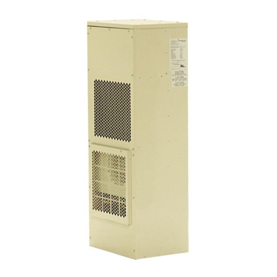
Panel Mounted Air Conditioners
by Dantherm Inc.
iA/C T-Series
iA/C T-A6000, -B6000, -B8000
with USACG-6 Control
PRODUCT INFORMATION MANUAL
AC-6 iAC 6K 8K Manual Rev B
Page 1 of 22
Dantherm, Inc.
110 Corporate Drive, Suite K
Spartanburg, SC 29303
Tel # +1 864 595 9800
Fax # +1 864 595 9810
Email: dantherm.usa@dantherm.com
Website: www.dantherm.com
Advertisement
Table of Contents

Related Manuals for Dantherm iA/C T-A6000, iA/C T-B6000, iA/C T-B8000


Summary of Contents for Dantherm iA/C T-A6000, iA/C T-B6000, iA/C T-B8000
- Page 1 Panel Mounted Air Conditioners by Dantherm Inc. iA/C T-Series iA/C T-A6000, -B6000, -B8000 with USACG-6 Control PRODUCT INFORMATION MANUAL AC-6 iAC 6K 8K Manual Rev B Page 1 of 22 Dantherm, Inc. 110 Corporate Drive, Suite K Spartanburg, SC 29303...
-
Page 2: Table Of Contents
iA/C T-Series Installation, Operating & Maintenance Manual Contents GENERAL SAFETY & WARNING INSTRUCTIONS ............... 3 UNPACKING, HANDLING & INITIAL INSPECTION ..............3 MODELS COVERED BY THIS MANUAL ..................4 ........................4 ODEL DENTIFICATION ......................4 ENERAL PERFORMANCE DIMENSIONS & INSTALLATION ....................... 5 .......................... -
Page 3: General Safety & Warning Instructions
iA/C T-Series Installation, Operating & Maintenance Manual 1 GENERAL SAFETY & WARNING INSTRUCTIONS Certain parts of electrical systems are inevitably live or have a high operating temperatures. Observe caution at all times. Failure to observe these conditions and installation instructions can cause injury and damage. ... -
Page 4: Models Covered By This Manual
iA/C T-Series Installation, Operating & Maintenance Manual 3 MODELS COVERED BY THIS MANUAL Model Identification The model numbering format is detailed below. A =115 Volt 1/Phase 50/60 Hz. B = 230 Volt 1/Phase 50/60 Hz. 6000 = 6000 BTU/Hr 8000 = 8000 BTU/Hr Option Codes H015 = Heater rating 1500W iA/C T-A6000-H015-Fl... -
Page 5: Dimensions & Installation
iA/C T-Series Installation, Operating & Maintenance Manual 4 DIMENSIONS & INSTALLATION Product Drawing 4.1.1 T-6000 & T-8000 with 8-hole mounting pattern AC-6 iAC 6K 8K Manual Rev B Page 5 of 22... -
Page 6: T-8000 With 11-Hole Mounting Pattern
iA/C T-Series Installation, Operating & Maintenance Manual 4.1.2 T-8000 with 11-hole mounting pattern AC-6 iAC 6K 8K Manual Rev B Page 6 of 22... -
Page 7: Mounting Template
iA/C T-Series Installation, Operating & Maintenance Manual Mounting template 4.2.1 T-6000 & T-8000 with 8-hole mounting pattern AC-6 iAC 6K 8K Manual Rev B Page 7 of 22... -
Page 8: T-8000 With 11-Hole Mounting Pattern
iA/C T-Series Installation, Operating & Maintenance Manual 4.2.2 T-8000 with 11-hole mounting pattern AC-6 iAC 6K 8K Manual Rev B Page 8 of 22... -
Page 9: Gasket Installation
(Common), black (Normally open) and white (Normally closed) wires only. The green wire is not used. If the interconnect function is to be used, connect the black and red wires on the small two wire interconnect cable to the corresponding interconnect cable supplied with each unit. Contact Dantherm for additional information. ... -
Page 10: Usacg-6 Intelligent Controller Operation
iA/C T-Series Installation, Operating & Maintenance Manual Check for the following: Airflow through both condenser and evaporator Abnormal vibration Temperature of cabinet supply air should be less than 70 F (21 C) when the ambient air is 80 F (27 C) or below. -
Page 11: Modify Cooling Set Point
iA/C T-Series Installation, Operating & Maintenance Manual Modify cooling set point Press L button for 2 seconds and release (Display will begin “Display Mode”) Press L&R button simultaneously for 2 seconds and release (Display will show “test”) Press R button for 2 seconds and release (Display will show “H SP”) Press R button for 2 seconds and release (Display will show “C SP”) Press L button for 2 seconds and release (Display will show current Cooling Set Point) Press and hold R button to raise setting (Maximum is 104... -
Page 12: Initiating The "Test" Sequence
iA/C T-Series Installation, Operating & Maintenance Manual Initiating the “TEST” sequence 5.5.2 1. Press L button for 2 seconds and release (Display will begin “Display Mode”) 2. Press L&R button simultaneously for 2 seconds and release (Display will show “test”) 3. -
Page 13: Maintenance
T-Series Installation, Operating & Maintenance Manual 6 MAINTENANCE Preventative Maintenance Schedule Dantherm Air Handling Inc Air Conditioner Preventative Maintenance Schedule 3 or 6 6 Monthly Yearly 5 Yearly Maintenance Item Monthly 1 Check enclosure air or ambient air filter (If applicable) -
Page 14: Evaporator And Condenser Coil Cleaning
The compressor is a hermetically sealed and factory lubricated unit and therefore requires no maintenance. If the compressor fails it is recommended that the unit be returned to Dantherm Inc. for servicing. In the event that the unit cannot be returned it is possible, using suitably qualified personnel, to repair the unit in the field. -
Page 15: Troubleshooting
To aid in service definition the service personnel can initially identify probable cause by referring to the following trouble shooting chart. If in doubt contact Dantherm Air Handling Inc. for assistance. Always have the Model #, Serial # available before you call. -
Page 16: Component Removal
iA/C T-Series Installation, Operating & Maintenance Manual Component Removal Internal Fan Removal Remove cover. Unscrew cover on top of air conditioner. Remove torx screws holding fan onto fan bracket. Detach wires and pull fan box out through top opening. Remove fan and replace by removing four phillips head screws. External Fan Removal - Remove bottom cover. -
Page 17: Overload Temperature Limiting Device
iA/C T-Series Installation, Operating & Maintenance Manual Control Board Removal - Remove front cover by unscrewing 9 torx screws. Now disconnect all wires and connectors to control board, unscrew the four phillips screws holding the control board down. Now the control can be removed. Note: When reinstalling the control board, the compressor wire going through the current sensor on the control board should be looped in order to maintain the correct current. -
Page 18: Wiring Diagram
iA/C T-Series Installation, Operating & Maintenance Manual Wiring Diagram 6.9.1 iA/C T-A/B6000 AC-6 iAC 6K 8K Manual Rev B Page 18 of 22... -
Page 19: Ia/C T-B8000
iA/C T-Series Installation, Operating & Maintenance Manual 6.9.2 iA/C T-B8000 AC-6 iAC 6K 8K Manual Rev B Page 19 of 22... -
Page 20: Spare Parts Guide
iA/C T-Series Installation, Operating & Maintenance Manual 6.10 Spare Parts Guide AC-6 iAC 6K 8K Manual Rev B Page 20 of 22... -
Page 21: Warranty
DANTHERM warrants that such DANTHERM products will be free from defects in materials and workmanship in normal use for a period of twelve (12) months from the date of the original purchase. Should any part of your DANTHERM product fail because of a... -
Page 22: Return Material Authorization Procedure
All product returns require a Return Material Authorization number regardless of reason. The customer is required to contact the Quality Department at Dantherm Inc. in Spartanburg, SC at +1 864 595 9800 to obtain an RMA number. ...
Need help?
Do you have a question about the iA/C T-A6000, iA/C T-B6000, iA/C T-B8000 and is the answer not in the manual?
Questions and answers