Advertisement
Quick Links
Advertisement

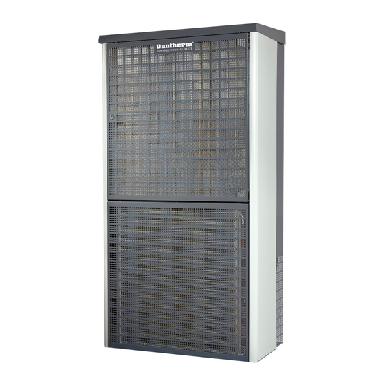
Summary of Contents for Dantherm Combo Cooling 10000/1000
- Page 1 Combo Cooling 10000/1000 Quick setup guide Rev. 0.56...
- Page 2 • Proper work attire (long sleeve shirt and long pants) Please strictly observe the following: Special Skill is required to install the Dantherm Combo Cooling units. Non-qualified personnel should not attempt any of the actions shown in this instal- lation guide. Dantherm shall not be responsible for improper installation or any accidents, dama-...
-
Page 3: Tools Needed
Tools needed DIN 10 mm 8-28x 8 mm 4 mm 3 mm 8 mm 4 mm 3 mm... - Page 4 Product dimension Imperial 23.54 in 1.93 in 42.20 in 31.50in 10.51 in 3.94 in 507 lbs ! 12.72 in 31.50 in 7.12 in 19.69 in 3.94 in 36.30 in 26.06 in 41.57 in Top view - exempted space Top view - service space 15.75 in 15.75 in 56.69 in...
- Page 5 Product dimension Metric 598 mm 49 mm 1072 mm 800 mm 267 mm 100 mm 230 kg ! 323 mm 800 mm 181 mm 500 mm 100 mm 922 mm 662 mm 1056 mm Top view - exempted space Top view - service space 400 mm 400 mm 1440 mm...
-
Page 6: Product Overview
Product overview Integrated rain hood Mounting frame Evaporator fan Left side panel Cooling air filter CC4 control board Evaporator Serial number label Damper Internal damper motor Condenser Cable entrance Condenser fan Lower air grill- condenser air inlet Compressor Condensate water drainage... - Page 7 ain hood Right side panel Free cooling air inlet Shown “Air Maze” is optional...
- Page 8 Remove covers Release lower air grill...
- Page 9 Release mou- ting frame Warning Caution 2x DIN 10 2x DIN 10 8 mm 4 mm 8 mm 4 mm 3 mm 3 mm Locate possible cable routing Controller board Terminal block AC+HEAT Display and temp sensor...
-
Page 10: Mounting Of Frame
Cut out min. 90 mm 275 mm 800 mm 323 mm 800 mm Warning 500 mm 25 mm Caution 364 mm 30 mm 30 mm min. 925 mm optimum 1125 mm Drill only cable or more inlet if needed Mounting of frame Warning 4 mm... - Page 11 Lifting unit onto bracket Warning Caution Hoist unit with forklift or equal placed under bottom main cabinet Securing and sealing 4x DIN 10 4 mm 8 mm 4 mm 3 mm...
- Page 12 Mounting dis- play 8 mm 4 mm 3 mm 8 mm 4 mm 3 mm...
- Page 13 Mounting in- door sensor Keep this space free for air flow...
- Page 14 Unit schematics - 400V/50Hz - 3 phase Orange=OK Warning External safety breaker Caution Not included 3 Phase Power Input 400V 50Hz C20A Fuse Compressor Black:L Blue:N Yellow:PWM Blue:GND Comp. control Heater Heater Heater Cond. fan Cond. fan Cond. fan output + output - output - Door SW...
- Page 15 Red: 48V Blue: GND White: Tach output Yellow: PWM Int. Fan Screw GND CC4 controller PCB board J2/Fan 1 Tacho Postive Tacho J3/Fan 2 Postive J7/Fan 3 Tacho Postive Compressor out + Compressor out - Damper supply Damper supply Damper GND Heater output + Heater output - Condensor fan output +...
- Page 16 Unit schematics - 240V/60Hz - 1 phase 1 Phase Power Input 240V 60Hz C40A fused Warning Caution External safety breaker Not included Compressor Capactior Black:L Blue:N Blue:GND Yellow:PWM Comp. control Heater Heater Heater Cond. fan Cond. fan Cond. fan output + output - output - Door SW...
- Page 17 Red: 48V Blue: GND White: Tach output Yellow: PWM Int. Fan Screw GND CC4 controller PCB board J2/Fan 1 Tacho Postive Tacho J3/Fan 2 Postive J7/Fan 3 Tacho Postive Compressor out + Compressor out - Damper supply Damper supply Damper GND Heater output + Heater output - Condensor fan output +...
-
Page 18: Controller Connections
Controller connections 1: Fan positive 2:Fan PWM 10A Mini blade terminal. 3:Fan tacho FX ”Littlefuse” type ”997 010” 4:Fan GND 1: Fan positive 2:Fan PWM 10A Mini blade terminal. 3:Fan tacho FX ”Littlefuse” type ”997 010” 4:Fan GND 1: Fan positive 2:Fan PWM 3:Fan tacho 10A Mini blade terminal. - Page 19 External safety breaker (not included) Warning Caution 48V DC negative 48VDC 20A fused 48V DC positive 97 010” -t° Room sensor 97 010” 0 / 12V DC Digital input 1 AL 2 with pull up Digital input 2 nal. Alarm 2 997 010”...
-
Page 20: Control Strategy
Control strategy Dampers Open Dampers Close Circulation mode Free Cooling mode Free Heater mode Setpoint Heater Setpoint Band heater Band Idle Band... - Page 21 Dampers Open Dampers Closed Emergency High Speed Mode AC mode Free Cooling mode Diff temp Diff temp 1 Diff temp 2 Shelter Temperature [°C] AC Start AC Start 1 AC Start 2...
- Page 22 Parameters Parameter Heater Set point Heater P band Idle band Set point cooling Cooling Pband High speed free cooling Start Internal air con Diff temp Start external aircon 1 Diff temp 1 Start external aircon 2 Diff temp 2...
- Page 23 Default...
- Page 24 Using the display Mode Idle Menu up Select Menu down Menu Step value up Store and return Step value down...
- Page 25 Dantherm can accept no responsibility for possible errors and changes - Irrtümer und Änderungen vorbehalten - Dantherm n’assume aucune respon- sabilité pour erreurs et modifications éventuelles - Dantherm se exime de cualquier responsabilidad por errores y cambios realizados.
- Page 27 Dantherm can accept no responsibility for possible errors and changes. Irrtümer und Änderungen vorbehalten. Dantherm n’assume aucune responsabilité pour erreurs et modifications éventuelles. Dantherm se exime de cualquier responsabilidad por errores y cambios realizados.
- Page 28 Dantherm Air Handling A/S Marienlystvej 65 7800 Skive Danmark www.dantherm.com service@dantherm.com...


Need help?
Do you have a question about the Combo Cooling 10000/1000 and is the answer not in the manual?
Questions and answers