Table of Contents
Advertisement
Quick Links
Advertisement
Table of Contents

Related Manuals for Dantherm DC 1000


Summary of Contents for Dantherm DC 1000
- Page 1 DC Air Conditioner 1000 Service manual Rev. 1.0...
- Page 2 Der tages forbehold for trykfejl og ændringer Dantherm can accept no responsibility for possible errors and changes Irrtümer und Änderungen vorbehalten Dantherm n’assume aucune responsabilité pour erreurs et modifications éventuelles...
-
Page 3: Table Of Contents
Copying of this service manual, or part of it, is forbidden without prior written permis- sion from Dantherm A/S. Reservations Dantherm reserves the right to make changes and improvements to the product and the service manual at any time without prior notice or obligation. Table of contents This service manual covers the following main topics: Introduction ........................ -
Page 4: Product Description
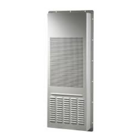
DC Air Conditioner 1000 removes dissipated heat from electronic equipment 1000 and it´s designed to maintain correct temperature for electronic equipment. Important Dantherm recommends that the cooling system should be running continuously! Section content Product description..................... 4 Overall description ....................4 Electronic control description ................ - Page 5 Overall description, continued Outdoor view This illustrates the unit outdoor visible parts Fig. 1 Parts description This tables shows outdoor parts according to Fig. 1 outdoor view Part Function Mounting frame Condenser air output Condenser air input Condensed water spigot Continued overleaf...
- Page 6 Overall description, continued Indoor view This illustrates the unit indoor visible parts Fig. 2 Parts description This tables shows indoor parts according Fig. 2 indoor view Part Function Evaporator air inlet Controller Service cover Evaporator fan blowing cold air out Serial number label Continued overleaf...
- Page 7 Overall description, continued Functionality The illustration and table below show the airflows of DC Air Conditioner 1000. The two air flows (internal/external) operate separately. External air is only used to cool down the condenser which dissipates the heat absorbed by the indoor evaporator. The air flows are not mixed Fig.
-
Page 8: Electronic Control Description
Electronic control description Introduction This section describes key features of the electronic control, and how it operates. WARNING Never carry out any installation, maintenance or service, without disconnecting the DC power supply, by means of the external power supply disconnecting devices. Installation Please incorporate the following when installing the electrical connections: requirements... - Page 9 Electronic control description, continued Alarms The controller has one hardware alarm output. Alarm output is a bi-directional dry contact. Max load 60V/50mA. Contact is closed on failure. Two LED’s indicates status of operation. LED indication Color STATUS Definition Green Power supply OK No power or Voltage out of range Flashing Selftest on-going.
- Page 10 Electronic control description, continued Data communication The controller has an RS 485 communication line with an embedded ModBus protocol. This interface has galvanic insulation. Communication settings: RS 485 specification Baud rate 9600 baud 8 bit Stop bit 1 bit Parity Cooling setpoint Cooling set point can be set between 20-40 °C in steps of 5°C.
-
Page 11: Connections
Connections Connection This illustration shows the control panel with connections. Fig. 4 Connection This describes the above connection: description Part Function Cooling set-point dial Alarm output, see specification at page 9 RJ45 – factory only Earth connection Reset switch Power input -44.0 to -58.0 VDC. Reverse polarity protected. LED feedback, see specification at page 9... -
Page 12: Installation
Installation Throug wall Please read the guide step by step Phase Description Cut a square of 415mm wide and 1115 mm high according the dimension shown in the specification part of this manual at page 21. 415 mm 1115 mm Mount unit from the inside, push it through the wall. -
Page 13: Service Guide
Service guide Overview Introduction This section gives all relevant information about servicing, spare parts and trouble shooting. Serial numbers Product model and serial numbers are found on the nameplate. Please have product model and serial numbers ready if you are contacting After Sales Support. -
Page 14: Preventive Maintenance
Preventive maintenance Introduction Preventive maintenance has to be carried out to: Anticipate a continues operation in product expected lifetime of 10 years or more Meet the warranty conditions Avoid malfunctions Avoid inefficient operation Maximize the unit’s lifetime The factory warranty is only valid if documented preventive maintenance has been car- ried out, with an time interval of: ... - Page 15 Preventive maintenance, continued Cooling circuit The cooling circuit should only be serviced by trained cooling technicians. The following steps is mandatory: Step Action Check for any leakages in all junctions, with a suitable leakage detector foam. Check the HP switch functionality. A.
-
Page 16: Electrical Schematic
Electrical schematic Electrical schematic This is the overall electrical schematic... -
Page 17: Cooling Circuit
Cooling circuit Introduction This section describes the active cooling system WARNING Never carry out any installation, maintenance or service, without disconnecting the AC power supply, by means of the external power supply disconnecting devices. Service on any cooling circuit with cooling refrigerant is only too carried out by a trained cooling technician. - Page 18 Locating cooling parts Fig. 6 Parts designation This tables shows the cooling part shown on Fig. 6 Pos. Part Evaporator Controller Condenser fan Expansion valve Evaporator fan Condenser High pressure switch (HP) Low pressure switch (LP) Receiver Compressor...
-
Page 19: Spare Part List
Spare part list Illustration Available spare parts for DC Air Conditioner 1000: Fig. 7 List List of spare parts including spare part numbers for DC Air Conditioner 1000: Pos. Description Main controller type CC3 218639 Compressor driver board CD-3 218712 DC supply filter 218649 EBM Fan 175mm... -
Page 20: Technical Data
Technical data Introduction This shows the data and dimensions for DC Air Conditioner 1000. Technical data This table shows the technical data for the DC Air Conditioner 1000 Dimensions, weight & mounting Unit dimensions (height×width×depth) 1170×470×170 / inch 46.1×18.5×6.7 Single packing dimensions 1341×580×310 / (height×width×depth) inch... - Page 21 Technical data, continued Dimensions Fig. 8 Continued overleaf...
- Page 22 Technical data, continued EC-Declaration of Dantherm A/S, Marienlystvej 65, DK-7800 Skive hereby declare that the units DC Air Conformity Conditioner 1000 are in conformity with the following directives: 2006/42/EC Directive on the safety of machines 2006/95/EC Low Voltage Directive 2004/108/EC...
-
Page 23: Contact Dantherm
+(0) 121 133 70 infodk@dantherm.com dantherm.no@dantherm.com infose@dantherm.com www.dantherm.com www.dantherm.no www.dantherm.se Dantherm Air Handling (Suzhou) Ltd. Dantherm Limited Dantherm Air Handling Inc. Bldg#9, No.855 Zhu Jiang Rd., 12 Windmill Business Park 110 Corporate Drive, Suite K Suzhou New District, Jiangsu Windmill Road, Clevedon... - Page 24 Dantherm Air Handling A/S Marienlystvej 65 7800 Skive Denmark www.dantherm.com service@dantherm.com...
Need help?
Do you have a question about the DC 1000 and is the answer not in the manual?
Questions and answers