Table of Contents
Advertisement
Quick Links
Advertisement
Chapters
Table of Contents

Related Manuals for IEI Technology POC-W22A-H81


Summary of Contents for IEI Technology POC-W22A-H81
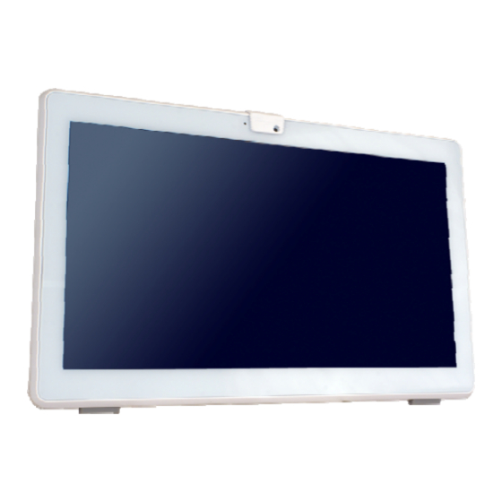
- Page 1 POC-W22A-H81 Medical Panel PC MODEL: POC-W22A-H81 21.5” Medical Panel PC with 4 Generation Intel® Dual-Core CPU, Touchscreen, Anti-bacteria Cover, Dual USB 3.0, Dual GbE LAN, RS-232/422/485, HDMI, VGA, Front IP 65 Rating and RoHS User Manual User Manual Page I...
- Page 2 POC-W22A-H81 Medical Panel PC Revision Date Version Changes October 17, 2016 1.00 Initial release Page II...
- Page 3 POC-W22A-H81 Medical Panel PC Copyright COPYRIGHT NOTICE The information in this document is subject to change without prior notice in order to improve reliability, design and function and does not represent a commitment on the part of the manufacturer. In no event will the manufacturer be liable for direct, indirect, special, incidental, or consequential damages arising out of the use or inability to use the product or documentation, even if advised of the possibility of such damages.
- Page 4 POC-W22A-H81 Medical Panel PC Manual Conventions WARNING Warnings appear where overlooked details may cause damage to the equipment or result in personal injury. Warnings should be taken seriously. CAUTION Cautionary messages should be heeded to help reduce the chance of losing data or damaging the product.
-
Page 5: Table Of Contents
POC-W22A-H81 Medical Panel PC Table of Contents 1 INTRODUCTION......................1 1.1 O ........................2 VERVIEW 1.2 M ....................3 ODEL ARIATIONS 1.3 F ........................4 EATURES 1.4 F ......................5 RONT ANEL 1.4.1 Backlit Touch Buttons ..................6 1.5 S ...................... - Page 6 POC-W22A-H81 Medical Panel PC 3.11 RS-232/422/485 S ............40 ERIAL ONNECTION 3.12 AT/ATX M ..................40 ELECTION 3.12.1 AT Power Mode....................40 3.12.2 ATX Power Mode ................... 41 3.13 C ................41 ABLE OVER NSTALLATION 3.14 M ..................42 OUNTING THE YSTEM 3.14.1 Wall Mounting....................
- Page 7 POC-W22A-H81 Medical Panel PC 5.1.4 BIOS Menu Bar....................77 5.2 M ........................77 5.3 A ....................... 79 DVANCED 5.3.1 ACPI Settings ....................80 5.3.2 RTC Wake Settings ................... 81 5.3.3 Trusted Computing ................... 82 5.3.4 CPU Configuration..................83 5.3.5 SATA Configuration ..................85 5.3.6 USB Configuration...................
- Page 8 POC-W22A-H81 Medical Panel PC 6.4 S ...................111 YSTEM EPLACEMENT 6.5 SO-DIMM R ..................112 EPLACEMENT 6.6 R ................114 EINSTALLING THE OVER 6.7 T ....................114 ROUBLESHOOTING A REGULATORY COMPLIANCE ................115 B SAFETY PRECAUTIONS ..................120 B.1 S ................... 121 AFETY RECAUTIONS B.1.1 General Safety Precautions ................121 B.1.2 Anti-static Precautions ..................
- Page 9 POC-W22A-H81 Medical Panel PC List of Figures Figure 1-1: POC-W22A-H81 Medical Panel PC ................2 Figure 1-2: Front View ........................5 Figure 1-3: Backlit Touch Buttons ....................6 Figure 1-4: Side View........................7 Figure 1-5: Bottom Panel .......................8 Figure 1-6: Rear View ........................8 Figure 1-7: Dimensions (mm) ......................13 Figure 3-1: Back Cover Retention Screws .................23...
- Page 10 POC-W22A-H81 Medical Panel PC Figure 3-25: IRFR Screen......................38 Figure 3-26: IRFR – Find Tags.....................38 Figure 3-27: IRFR – UIDs......................39 Figure 3-28: AT/ATX Switch Location..................40 Figure 3-29: Aligning Tabs on the Bottom Panel ..............41 Figure 3-30: Cable Cover Installation ..................41 Figure 3-31: Cable Cover Removal .....................42 Figure 3-32: Wall-mounting Bracket ...................43...
- Page 11 POC-W22A-H81 Medical Panel PC Figure 4-21: Driver Installation Complete Window ..............66 Figure 4-22: Device Manager Window–SCR Device..............66 Figure 4-23: Device Manager - Update Driver Software............67 Figure 4-24: Update Driver Software Window ................68 Figure 4-25: Browse for Driver Software Window..............68 Figure 4-26: Installing Driver Window ..................69 Figure 4-27: Driver Installation Complete Window ..............69...
- Page 12 POC-W22A-H81 Medical Panel PC List of Tables Table 1-1: Model Variations ......................3 Table 1-2: Touch Button Functions ....................6 Table 1-3: System Specifications....................12 Table 3-1: Handset Button Functions..................31 Table 3-2: RS-232/422/485 Serial Port Pinouts ................40 Table 5-1: BIOS Navigation Keys ....................76...
- Page 13 POC-W22A-H81 Medical Panel PC List of BIOS Menus BIOS Menu 1: Main ........................78 BIOS Menu 2: Advanced ......................79 BIOS Menu 3: ACPI Settings .......................80 BIOS Menu 4: RTC Wake Settings ....................81 BIOS Menu 5: Trusted Computing ....................82 BIOS Menu 6: CPU Configuration ....................83 BIOS Menu 7: SATA Configuration .....................85...
-
Page 15: Introduction
POC-W22A-H81 Medical Panel PC Chapter Introduction Page 1... -
Page 16: Overview
Intel® Core™/Pentium® CPU powered medical-grade panel PC with a rich variety of functions and peripherals. All POC-W22A-H81 models are designed for easy and simplified integration into point-of-care (POC) applications. An Intel® Core™ i5/Core™ i3/Pentium® processor coupled with the Intel® H81 chipset delivers optimal memory, graphics, and peripheral I/O support. -
Page 17: Model Variations
1.2 Model Variations There are three models in the POC-W22A-H81 series. All models are preinstalled with two 2 GB DDR3 memory modules and an 802.11a/b/n/ac Wi-Fi module. The model numbers and model variations are listed below. -
Page 18: Features
POC-W22A-H81 Medical Panel PC 1.3 Features The POC-W22A-H81 features are listed below: 21.5” (16:9) flat-bezel LCD with LED backlight Anti-bacteria cover 4th generation Intel® Core™ i5, Core™ i3 or Pentium ® processor Pre-installed with 4 GB of DDR3 SO-DIMM memory (system max. 16 GB) ... -
Page 19: Front Panel
POC-W22A-H81 Medical Panel PC 1.4 Front Panel The front side of the POC-W22A-H81 is a flat-bezel panel with a TFT LCD screen surrounded by a PC/ABS plastic frame (Figure 1-2). Figure 1-2: Front View If the POC-W22A-H81 is installed with an optional UPS battery module, there will be a battery LED indicator located on the front panel. -
Page 20: Backlit Touch Buttons
POC-W22A-H81 Medical Panel PC 1.4.1 Backlit Touch Buttons The front panel of the POC-W22A-H81 contains several backlit touch buttons that control audio volume, LCD brightness and some other system components. Figure 1-3: Backlit Touch Buttons The following table describes the function of each button. -
Page 21: Side Panels
I/O interface expansion by installing a PCIe Mini I/O card. Figure 1-4: Side View 1.6 Bottom Panel The bottom panel of the POC-W22A-H81 has the following connectors and switches (Figure 1-5): 1 x 12 V ~ 28 V DC input power jack ... -
Page 22: Rear Panel
POC-W22A-H81 Medical Panel PC Figure 1-5: Bottom Panel 1.7 Rear Panel The rear panel provides access to retention screw holes that support VESA mounting. See Figure 1-6. Figure 1-6: Rear View Page 8... -
Page 23: System Specifications
POC-W22A-H81 Medical Panel PC 1.8 System Specifications The technical specifications for the POC-W22A-H81 systems are listed in Table 1-3. Specification POC-W22A-H81 Intel® Pentium® G3320TE (dual-core, 2.3 GHz, TDP 35 W) Intel® Core™ i3-4330TE (dual-core, 2.4 GHz, TDP 35 W) Intel® Core™ i5-4570TE (dual-core, 2.7 GHz, TDP 35 W) Intel®... - Page 24 POC-W22A-H81 Medical Panel PC Surface Hardness Network Connection Wireless One pre-installed wireless LAN module (half-size PCIe Mini card) supports 802.11a/b/g/n/ac Dual GbE connector Audio Realtek ALC892 HD Audio codec Audio Internal Speaker Two 3 W speakers 2-megapixel with auto focus and digital microphone...
- Page 25 POC-W22A-H81 Medical Panel PC 4 x USB 2.0 connectors 1 x VGA connector Buttons, Switches and Indicators Backlit Touch Buttons Six touch buttons (LCD on/off, brightness up, brightness down, volume up, volume down, lock/unlock touch function) Buttons & Switches 1 x Power button...
-
Page 26: Table 1-3: System Specifications
POC-W22A-H81 Medical Panel PC Non-Operating Shock: 15G peak acceleration (11ms duration) IP Level IP 65 compliant front panel CE, FCC class B part 18, UL 60601-1, EN 60601-1 Safety/EMC Power Power Supply 120 W medical-grade power adapter (FSP PMP120-13-2) Input: 100 V AC ~ 240 V AC, 47 Hz ~ 63 Hz, 1.4 A ~ 0.6 A Output: 120 W Max., 19 V... -
Page 27: Dimensions
POC-W22A-H81 Medical Panel PC 1.9 Dimensions The POC-W22A-H81 dimensions are shown below. Figure 1-7: Dimensions (mm) Page 13... -
Page 28: Unpacking
POC-W22A-H81 Medical Panel PC Chapter Unpacking Page 14... -
Page 29: Unpacking
POC-W22A-H81 Medical Panel PC 2.1 Unpacking To unpack the medical panel PC, follow the steps below: WARNING! The front side LCD screen has a protective plastic cover stuck to the screen. Only remove the plastic cover after the medical panel PC has been properly installed. -
Page 30: Packing List
Contact the IEI reseller or vendor the POC-W22A-H81 was purchased from or contact an IEI sales representative directly by sending an email to ales@ieiworld.com. The POC-W22A-H81 medical panel PC is shipped with the following components: Quantity Item Image POC-W22A-H81 medical panel PC... -
Page 31: Optional Items
POC-W22A-H81 Medical Panel PC Utility CD One Key Recovery CD 2.3 Optional Items The following are optional components which may be separately purchased: Item and Part Number Image 3-in-1 reader (smart card / magnetic card / fingerprint) (P/N: MEDP-CR-R10) Handle... - Page 32 POC-W22A-H81 Medical Panel PC Item and Part Number Image Handset (USB interface) and holder (P/N: MEDP-HS-R10) Cable cover (P/N: POCP-CC01-R10) EZ Stand with cabling hole, VESA 100 (P/N: MEDP-EZS-R10) VESA 100 wall mount kit (four M3*6 screws included) (P/N: AFLWK-19B)
- Page 33 POC-W22A-H81 Medical Panel PC Item and Part Number Image iRIS module (assemble-to-order) (P/N: iRIS-2400-R10) Trusted platform module (assemble-to-order) (P/N: MEDP-TPM-R10) 14.8 V 3550 mAH Li-ion battery (Getac BAT003-4S1P3550-0, assemble-to-order) (P/N: MEDP-BAT-R10) Mifare RFID reader compliant with ISO 14443A, ISO 14443B and ISO 15693 protocols (assemble-to-order)
-
Page 34: Installation
POC-W22A-H81 Medical Panel PC Chapter Installation Page 20... -
Page 35: Anti-Static Precautions
POC-W22A-H81 and severe injury to the user. Electrostatic discharge (ESD) can cause serious damage to electronic components, including the POC-W22A-H81. Dry climates are especially susceptible to ESD. It is therefore critical that whenever the POC-W22A-H81 is accessed internally, or any other electrical component is handled, the following anti-static precautions are strictly adhered ... -
Page 36: Installation And Configuration Steps
Step 6: Step 0: 3.4 Removing the Back Cover To access the POC-W22A-H81 internally the back cover must be removed. To remove the back cover, please follow the steps below. Remove the two retention screws from the back cover (Figure 3-1). -
Page 37: Figure 3-1: Back Cover Retention Screws
POC-W22A-H81 Medical Panel PC Figure 3-1: Back Cover Retention Screws The back cover is attached to the chassis through a magnetic force. To remove Step 2: the back cover, grasp the back cover finger grips (as shown in Figure 3-2) and lift the cover up. -
Page 38: Hdd Installation
POC-W22A-H81 Medical Panel PC 3.5 HDD Installation To install the HDD into the system, please follow the steps below: Remove the back cover. See Section 3.4 above. Step 1: Remove the two HDD bracket retention screws (Figure 3-3) and lift the HDD Step 2: bracket off the panel PC. -
Page 39: Figure 3-5: Hdd Retention Screws
Slide the bottom bracket into the HDD cover (Figure 3-6). Step 5: Figure 3-6: HDD Cover Installation Install the HDD into the POC-W22A-H81 by inserting and connecting the HDD to Step 6: the SATA connectors. Then, secure the HDD bracket to the chassis with the previously removed retention screws. -
Page 40: Ups Battery
The LED status descriptions are described in Section 1.4. CAUTION: The following precautions should be followed when using the battery: Do not use battery power to boot up the POC-W22A-H81. Charge the battery with a voltage higher than 16.8 V. Charging time (from 30% to 100%): ... -
Page 41: Handset Installation (Optional)
POC-W22A-H81 Medical Panel PC 3.7 Handset Installation (Optional) An optional phone handset can be installed on the side of the POC-W22A-H81 to make VoIP calls. To install the handset and the holder, please follow the instruction below. Locate the two retention screw holes for installing the handset holder on the rear Step 1: panel. -
Page 42: Using Voip Handset
POC-W22A-H81 Medical Panel PC Figure 3-9: Handset Installation 3.7.1 Using VoIP Handset The VoIP handset is designed for Skype. To use the handset to place or receive a call via Skype, please follow the steps below. Install the Skype program (http://www.skype.com/en/). -
Page 43: Figure 3-11: Handset Driver Installation
POC-W22A-H81 Medical Panel PC Follow the step-by-step instruction of the installation wizard (Figure 3-11) to Step 3: install the handset driver. Figure 3-11: Handset Driver Installation Launch Skype. Press the Allow access button on Skype (Figure 3-12) to allow Step 4: handset API access. -
Page 44: Figure 3-13: Manage Program Access To Skype
POC-W22A-H81 Medical Panel PC Figure 3-13: Manage Program Access to Skype The user can now use Skype via the handset. The function description of each Step 5: button on the handset is listed in the following table. Page 30... -
Page 45: Handle Installation (Optional)
Table 3-1: Handset Button Functions 3.8 Handle Installation (Optional) An optional handle can be installed on the POC-W22A-H81 for the user to easily adjust the viewing angle and the position of the POC-W22A-H81. To install the handle, please follow the instruction below. -
Page 46: Barcode Reader Installation
Insert the barcode reader set into the slot in the center of the handle. To be able Step 2: to insert the barcode reader, the side with barcode reader must face toward the right side of the POC-W22A-H81 as shown in Figure 3-15. Page 32... -
Page 47: Figure 3-15: Insert Barcode Reader Set
POC-W22A-H81 Medical Panel PC Figure 3-15: Insert Barcode Reader Set Push the barcode reader set all the way down, and then rotate the barcode Step 3: reader anti-clockwise to a proper position (Figure 3-16). Connect the barcode reader cable to the RJ-11 connector on the bottom panel of Step 4: the POC-W22A-H81 (Figure 3-16). -
Page 48: Reading Light
POC-W22A-H81 Medical Panel PC Figure 3-17: Barcode Reader Button WARNING: Do not stare into beam of the laser light. The human eye can be damaged. Avoid that the laser beam hits reflective surfaces such as mirrors, etc. Any changes at the device are forbidden these could cause a dangerous laser light. -
Page 49: 3-In-1 Combo Reader Installation (Optional)
POC-W22A-H81 Medical Panel PC 3.9 3-in-1 Combo Reader Installation (Optional) The 3-in-1 combo reader is an optional item for the POC-W22A-H81. The combo reader combines fingerprint reader, smart card reader (SCR) and magnetic stripe reader (MSR) into one compact device. -
Page 50: Figure 3-21: Combo Reader Installation
POC-W22A-H81 Medical Panel PC Figure 3-21: Combo Reader Installation Secure the combo reader to the system by inserting two retention screws Step 4: (M3x5L) into the rear panel of the POC-W22A-H81 and tightening them. Figure 3-22: Secure the Combo Reader Page 36... -
Page 51: Using Rfid Reader (Optional)
Section 4.12.3: Fingerprint Reader Driver 3.10 Using RFID Reader (Optional) The POC-W22A-H81 may come with an optional RFID reader pre-installed inside the bottom of the front panel. To use the RFID reader, follow the steps below. Install the RFID driver (refer to Section 4.11). -
Page 52: Figure 3-25: Irfr Screen
POC-W22A-H81 Medical Panel PC The IRFR-100 window appears ( Step 4: F igure 3-25). Figure 3-25: IRFR Screen Select the Find tags tab and click the Run button to enable the RFID reader Step 5: F igure 3-26). Figure 3-26: IRFR – Find Tags... -
Page 53: Figure 3-27: Irfr - Uids
POC-W22A-H81 Medical Panel PC Place an RFID card near the RFID reader on the bottom of the front Step 6: panel (Figure 1-2) then remove it. The card number will be shown in the UIDs column ( F igure 3-27). -
Page 54: Rs-232/422/485 Serial Port Connection
Table 3-2: RS-232/422/485 Serial Port Pinouts 3.12 AT/ATX Mode Selection AT or ATX power mode can be used on the POC-W22A-H81. The selection is made through an AT/ATX switch located on the bottom panel (Figure 3-28). Figure 3-28: AT/ATX Switch Location 3.12.1 AT Power Mode... -
Page 55: Atx Power Mode
3.13 Cable Cover Installation An optional cable cover can be installed on the POC-W22A-H81 for the user to easily manage cables. To install the cable cover, please follow the instruction below. Align the three tabs on the rear of the cable cover with the slots on the bottom Step 1: panel of the POC-W22A-H81 (Figure 3-29). -
Page 56: Mounting The System
POC-W22A-H81 Medical Panel PC To remove the cable cover, push the two tabs inwards to release the cover Step 3: (Figure 3-31), and lift the cover from the POC-W22A-H81. Figure 3-31: Cable Cover Removal 3.14 Mounting the System The methods of mounting the POC-W22A-H81 are listed below. -
Page 57: Wall Mounting
POC-W22A-H81 Medical Panel PC 3.14.1 Wall Mounting To mount the medical panel PC onto the wall, please follow the steps below. Select the location on the wall for the wall-mounting bracket. Step 1: Carefully mark the locations of the four screw holes in the bracket on the wall. - Page 58 POC-W22A-H81 Medical Panel PC Insert the four monitor mounting screws provided in the wall mount kit into the Step 6: four screw holes on the real panel of the medical panel PC and tighten until the screw shank is secured against the rear panel (Figure 3-33).
-
Page 59: Figure 3-33: Chassis Support Screws
POC-W22A-H81 Medical Panel PC Figure 3-33: Chassis Support Screws Secure the panel PC by fastening the retention screw of the wall-mounting Step 9: bracket (Figure 3-34). Figure 3-34: Secure the Panel PC Page 45... -
Page 60: Arm Mounting
3.14.2 Arm Mounting The POC-W22A-H81 is VESA (Video Electronics Standards Association) compliant and can be mounted on an arm with a 100 mm interface pad. To mount the POC-W22A-H81 on an arm, please follow the steps below. The arm is a separately purchased item. Please correctly mount the arm onto Step 1: the surface it uses as a base. -
Page 61: Stand Mounting
S t e p 0 : Figure 3-36: Arm Mounting 3.14.3 Stand Mounting To mount the POC-W22A-H81 using the EZ stand mounting kit, please follow the steps below. Locate the VESA mount screw holes on the rear of the POC-W22A-H81 Step 1: (Figure 3-35). -
Page 62: Powering On The System
POC-W22A-H81 Medical Panel PC Figure 3-37: Stand Mounting with EZ Stand (MEDP-EZS-R10) NOTE: If the EZ stand is mounted, the handle (MEDP-HD-R10 or MEDP-HD-BR-R10) can not be installed. 3.15 Powering On the System WARNING: To avoid risk of electric shock, this equipment must only be connected to supply mains with protective earth. -
Page 63: Reset The System
Connect the power cord to the power adapter. Connect the other end of the Step 1: power cord to a power source. Connect the power adapter to the power connector of the POC-W22A-H81. Step 2: Locate the power button on the I/O panel. -
Page 64: Driver Installation
POC-W22A-H81 Medical Panel PC Chapter Driver Installation Page 50... -
Page 65: Available Software Drivers
Visit the IEI website or contact technical support for the latest updates. All the drivers for the POC-W22A-H81 are on the utility CD that came with the system. To install the drivers, please follow the steps below. -
Page 66: Intel® Chipset Driver
POC-W22A-H81 Medical Panel PC 4.2 Intel® Chipset Driver To install the chipset driver, please follow the steps below. Select Chipset from the list of the driver CD. Step 1: Double click the setup file in the folder. The Intel® Chipset Device Software... -
Page 67: Audio Driver
POC-W22A-H81 Medical Panel PC Figure 4-3: Intel® Graphics Driver InstallShield Wizard Follow the step-by-step instruction of the installation wizard to install the Step 3: graphics driver. 4.4 Audio Driver To install the driver for the speaker and the microphone, please follow the steps below. -
Page 68: Lan Driver
POC-W22A-H81 Medical Panel PC Figure 4-4: Realtek HD Audio Driver InstallShield Wizard Follow the step-by-step instruction of the installation wizard to install the HD Step 3: Audio driver. 4.5 LAN Driver To install the LAN driver, please follow the steps below. -
Page 69: Usb 3.0 Driver
POC-W22A-H81 Medical Panel PC Figure 4-5: LAN Driver Install Wizard Follow the step-by-step instruction of the installation wizard to install the Intel® Step 3: Network Connection driver. 4.6 USB 3.0 Driver To install the USB 3.0 driver, please follow the steps below. -
Page 70: Intel® Management Engine
POC-W22A-H81 Medical Panel PC Figure 4-6: USB 3.0 Driver Install Wizard Follow the step-by-step instruction of the installation wizard to install the Step 3: USB 3.0 driver. 4.7 Intel® Management Engine To install the Intel® Management Engine Components, please follow the steps below. -
Page 71: Keypad Ap
POC-W22A-H81 Medical Panel PC Figure 4-7: Intel® ME Components Install Wizard Follow the step-by-step instruction of the installation wizard to install the Intel® Step 3: Management Engine Components. 4.8 Keypad AP The Keypad AP is an OSD control tool developed by IEI. To install the Keypad AP, please follow the steps below. -
Page 72: Figure 4-8: Keypad Setup Wizard
POC-W22A-H81 Medical Panel PC Figure 4-8: Keypad Setup Wizard Follow the step-by-step instruction of the installation wizard to install the Keypad Step 3: After the installation, the Keypad AP can be accessed by pressing the Step 4: brightness up/down buttons or the volume up/down buttons on the bottom frame of the monitor. -
Page 73: Wireless Lan Driver
POC-W22A-H81 Medical Panel PC 4.9 Wireless LAN Driver To install the wireless LAN driver, please follow the steps below. Select WiFi from the list of the driver CD. Locate the setup file in this folder: Step 1: AZ_RTL8821AE_Win7_Win8.X__2012.9.0212.2014. Double click the setup file in the folder. The InstallShield Wizard screen appears Step 2: (Figure 4-10). -
Page 74: Rfid Driver (Optional)
POC-W22A-H81 Medical Panel PC Figure 4-11: Bluetooth Driver InstallShield Wizard Follow the step-by-step instruction of the installation wizard to install the Step 3: Bluetooth driver. 4.11 RFID Driver (Optional) To install the RFID driver, please follow the steps below. Open the Device Manager window. Long press or right click USB <-> Serial. -
Page 75: Figure 4-12: Device Manager - Update Driver Software
POC-W22A-H81 Medical Panel PC Figure 4-12: Device Manager - Update Driver Software The Update Driver Software window appears. Select Browse my computer Step 2: for driver software. Figure 4-13: Update Driver Software Window Page 61... -
Page 76: Figure 4-14: Browse For Driver Software Window
POC-W22A-H81 Medical Panel PC The following window appears. Press/Click the Browse button to specify the Step 3: RFID driver directory (\Docs\10.Other\ POCP-MF-RFID-R10\RFID\D490). Then, press/click the Next button. Figure 4-14: Browse for Driver Software Window The system starts installing the RFID driver. -
Page 77: 3-In-1 Combo Reader Driver (Optional)
POC-W22A-H81 Medical Panel PC Repeat to install the RFID driver again. Step 6: Step 1 ~ Step 5 The Device Manager Window now shows the installed RFID devices. Step 7: Figure 4-16: Device Manager Window–RFID Devices 4.12 3-in-1 Combo Reader Driver (Optional) The drivers for the optional 3-in-1 combo reader are all located in the following folder of the driver CD: \Docs\10.Other\POCP-W22A-CR-R10. -
Page 78: Figure 4-17: Device Manager - Update Driver Software
POC-W22A-H81 Medical Panel PC Figure 4-17: Device Manager - Update Driver Software The Update Driver Software window appears. Select Browse my computer Step 2: for driver software. Figure 4-18: Update Driver Software Window Page 64... -
Page 79: Figure 4-19: Browse For Driver Software Window
POC-W22A-H81 Medical Panel PC The following window appears. Press/Click the Browse button to specify the Step 3: SCR driver directory (\Docs\10.Other\POCP-W22A-CR-R10\SCR). Then, press/click the Next button. Figure 4-19: Browse for Driver Software Window The following window (Figure 4-20) appears as the driver is installed. -
Page 80: Figure 4-21: Driver Installation Complete Window
POC-W22A-H81 Medical Panel PC After the driver installation process is complete, a confirmation screen appears. Step 5: Click Close to exit the program. Figure 4-21: Driver Installation Complete Window The Device Manager Window now shows the installed SCR device. Step 6: Figure 4-22: Device Manager Window–SCR Device... -
Page 81: Msr Driver
POC-W22A-H81 Medical Panel PC 4.12.2 MSR Driver Follow the steps below to install the MSR driver. Open the Device Manager window. Long press or right click Singular VCOM Step 1: Card Reader. Select Update Driver Software from the pop-up window. -
Page 82: Figure 4-24: Update Driver Software Window
POC-W22A-H81 Medical Panel PC Figure 4-24: Update Driver Software Window The following window appears. Press/Click the Browse button to specify the Step 3: MSR driver directory (\Docs\10.Other\POCP-W22A-CR-R10\MSR). Then, press/click the Next button. Figure 4-25: Browse for Driver Software Window The following window (Figure 4-26) appears as the driver is installed. -
Page 83: Figure 4-26: Installing Driver Window
POC-W22A-H81 Medical Panel PC Figure 4-26: Installing Driver Window After the driver installation process is complete, a confirmation screen appears. Step 5: Click Close to exit the program. Figure 4-27: Driver Installation Complete Window The Device Manager Window now shows the installed MSR device. -
Page 84: Fingerprint Reader Driver
POC-W22A-H81 Medical Panel PC Figure 4-28: Device Manager Window–MSR Device 4.12.3 Fingerprint Reader Driver Follow the steps below to install the fingerprint reader driver. Select Other from the list of the driver CD. Step 1: The fingerprint reader driver is located in the following folder (Figure 4-29): Step 2: \Docs\10.Other\POCP-W22A-CR-R10\Finger Printer. -
Page 85: Figure 4-29: Fingerprint Reader Driver Folder
POC-W22A-H81 Medical Panel PC Figure 4-29: Fingerprint Reader Driver Folder The Egis ES603 WDM Driver welcome window appears. Step 3: Figure 4-30: Fingerprint Reader Driver InstallShield Wizard Follow the step-by-step instruction of the installation wizard to install the Step 4: fingerprint reader driver. -
Page 86: Barcode Reader Driver (Optional)
POC-W22A-H81 Medical Panel PC 4.13 Barcode Reader Driver (Optional) To install the barcode reader driver, please follow the steps below. Select Other from the list of the driver CD. Double click the Install_x86.bat file Step 1: (or Install_x64.bat for 64-bit OS) in the POCP-W22A-HD-BR-R10 folder shown... -
Page 87: Figure 4-33: Device Manager Window-Barcode Reader Device
POC-W22A-H81 Medical Panel PC Figure 4-33: Device Manager Window–Barcode Reader Device Page 73... -
Page 88: Bios Setup
POC-W22A-H81 Medical Panel PC Chapter BIOS Setup Page 74... -
Page 89: Introduction
POC-W22A-H81 Medical Panel PC 5.1 Introduction A licensed copy of the BIOS is preprogrammed into the ROM BIOS. The BIOS setup program allows users to modify the basic system configuration. This chapter describes how to access the BIOS setup program and the configuration options that may be changed. -
Page 90: Using Setup
POC-W22A-H81 Medical Panel PC 5.1.2 Using Setup Use the arrow keys to highlight items, press E to select, use the PageUp and NTER PageDown keys to change entries, press F1 for help and press E to quit. Navigation keys are shown in the following table. -
Page 91: Bios Menu Bar
POC-W22A-H81 Medical Panel PC 5.1.4 BIOS Menu Bar The menu bar on top of the BIOS screen has the following main items: Main – Changes the basic system configuration. Advanced – Changes the advanced system settings. Chipset – Changes the chipset settings. -
Page 92: Bios Menu 1: Main
POC-W22A-H81 Medical Panel PC Aptio Setup Utility – Copyright (C) 2015 American Megatrends, Inc. Main Advanced Chipset Boot Security Save & Exit Server Mgmt BIOS Information Set the Date. Use Tab to BIOS Vendor American Megatrends switch between Data Core Version 4.6.5.4... -
Page 93: Advanced
POC-W22A-H81 Medical Panel PC System Date [xx/xx/xx] Use the System Date option to set the system date. Manually enter the day, month and year. System Time [xx:xx:xx] Use the System Time option to set the system time. Manually enter the hours, minutes and seconds. -
Page 94: Acpi Settings
POC-W22A-H81 Medical Panel PC 5.3.1 ACPI Settings The ACPI Settings menu (BIOS Menu 3) configures the Advanced Configuration and Power Interface (ACPI) options. Aptio Setup Utility – Copyright (C) 2015 American Megatrends, Inc. Advanced ACPI Settings Select ACPI sleep state... -
Page 95: Rtc Wake Settings
POC-W22A-H81 Medical Panel PC 5.3.2 RTC Wake Settings The RTC Wake Settings menu (BIOS Menu 4) configures RTC wake event. Aptio Setup Utility – Copyright (C) 2015 American Megatrends, Inc. Advanced Wake system with Fixed Time [Disabled] Enable or disable System wake on alarm event. -
Page 96: Trusted Computing
POC-W22A-H81 Medical Panel PC If selected, the following appears with values that Enabled can be selected: *Wake up every day *Wake up date *Wake up hour *Wake up minute *Wake up second After setting the alarm, the computer turns itself on from a suspend state when the alarm goes off. -
Page 97: Cpu Configuration
POC-W22A-H81 Medical Panel PC Security Device Support [Enable] Use the Security Device Support option to configure support for the security devices. Security device support is disabled. Disable Security device support is enabled. Enable EFAULT 5.3.4 CPU Configuration Use the CPU Configuration (BIOS Menu 6) to view detailed CPU specifications and configure the CPU. -
Page 98: Hyper-Threading [Enabled]
POC-W22A-H81 Medical Panel PC Max CPU Speed: Lists the maximum CPU processing speed. Min CPU Speed: Lists the minimum CPU processing speed. CPU Speed: Lists the CPU processing speed. Processor Cores: Lists the number of the processor core ... -
Page 99: Sata Configuration
POC-W22A-H81 Medical Panel PC Intel Virtualization Technology [Disabled] Use the Intel Virtualization Technology option to enable or disable virtualization on the system. When combined with third party software, Intel® Virtualization technology allows several OSs to run on the same system at the same time. -
Page 100: Usb Configuration
POC-W22A-H81 Medical Panel PC SATA Controller(s) [Enabled] Use the SATA Controller(s) option to configure the SATA controller(s). Enable the on-board SATA controller(s). Enabled EFAULT Disable the on-board SATA controller(s). Disabled SATA Mode Selection [IDE] Use the SATA Mode Selection option to determine how SATA devices operate. -
Page 101: F81866 Super Io Configuration
POC-W22A-H81 Medical Panel PC USB Devices The USB Devices Enabled field lists the USB devices that are enabled on the system Legacy USB Support [Enabled] Use the Legacy USB Support BIOS option to enable USB mouse and USB keyboard support. -
Page 102: Serial Port N Configuration
POC-W22A-H81 Medical Panel PC 5.3.7.1 Serial Port n Configuration Use the Serial Port n Configuration menu (BIOS Menu 10) to configure the serial port n. Aptio Setup Utility – Copyright (C) 2015 American Megatrends, Inc. Advanced Serial Port 1 Configuration... -
Page 103: Serial Port 2 Configuration
POC-W22A-H81 Medical Panel PC Serial Port I/O port address is 3F8h and the IO=3F8h; interrupt address is IRQ3, 4 IRQ=3, 4 Serial Port I/O port address is 2C0h and the IO=2C0h; interrupt address is IRQ3, 4 IRQ=3, 4 ... -
Page 104: Iwdd H/W Monitor
POC-W22A-H81 Medical Panel PC Serial Port I/O port address is 2F8h and the IO=2F8h; interrupt address is IRQ3, 4 IRQ=3, 4 Serial Port I/O port address is 2C0h and the IO=2C0h; interrupt address is IRQ3, 4 IRQ=3, 4 ... -
Page 105: Smart Fan Mode Configuration
POC-W22A-H81 Medical Panel PC Fan Speed CPU fan System fan Voltages: CPU_CORE +12V +DDR +5VSB +3.3V +3.3VSB 5.3.8.1 Smart Fan Mode Configuration Use the Smart Fan Mode Configuration submenu (BIOS Menu 12) to configure fan speed settings. Aptio Setup Utility – Copyright (C) 2015 American Megatrends, Inc. -
Page 106: Fan Start/Off Temperature
POC-W22A-H81 Medical Panel PC The fan spins at the speed set in Manual Mode Manual Mode settings. The fan adjusts its speed using Auto Mode Auto Mode EFAULT settings. Fan start/off temperature Use the + or – key to change the Fan start/off temperature value. Enter a decimal number between 1 and 100. -
Page 107: Serial Port Console Redirection
POC-W22A-H81 Medical Panel PC 5.3.9 Serial Port Console Redirection The Serial Port Console Redirection menu (BIOS Menu 13) allows the console redirection options to be configured. Console redirection allows users to maintain a system remotely by re-directing keyboard input and text output through the serial port. -
Page 108: Iei Feature
POC-W22A-H81 Medical Panel PC 5.3.10 IEI Feature Use the IEI Feature menu (BIOS Menu 14) to configure One Key Recovery function. Aptio Setup Utility – Copyright (C) 2015 American Megatrends, Inc. Advanced iEi Feature Auto Recovery Function Reboot and recover... -
Page 109: Chipset
POC-W22A-H81 Medical Panel PC 5.4 Chipset Use the Chipset menu (BIOS Menu 15) to configure the system chipset. Aptio Setup Utility – Copyright (C) 2015 American Megatrends, Inc. Main Advanced Chipset Boot Security Save & Exit Server Mgmt > PCH-IO Configuration PCH Parameters >... -
Page 110: Pci Express Configuration
POC-W22A-H81 Medical Panel PC Restore AC Power Loss [Last State] Use the Restore AC Power BIOS option to specify what state the system returns to if there is a sudden loss of power to the system. The system remains turned off Power Off ... -
Page 111: Pch Azalia Configuration
POC-W22A-H81 Medical Panel PC Gen 1 Detect Non-Compliance Device [Disabled] Use the Detect Non-Compliance Device option to enable or disable detecting if a non-compliance PCI Express device is connected to the PCI Express slot. Disables to detect if a non-compliance PCI... -
Page 112: System Agent (Sa) Configuration
POC-W22A-H81 Medical Panel PC Azalia(HD Audio) [Enabled] Use the Azalia(HD Audio) BIOS option to enable or disable the High Definition Audio controller. The High Definition Audio controller is disabled. Disabled The High Definition Audio controller is enabled. -
Page 113: Graphics Configuration
POC-W22A-H81 Medical Panel PC 5.4.2.1 Graphics Configuration Use the Graphics Configuration menu ( B IOS Menu 20) to configure the graphics settings. Aptio Setup Utility – Copyright (C) 2015 American Megatrends, Inc. Chipset Graphics Configuration Select which of Auto/IGFX/PCIE Graphics... -
Page 114: Dvmt Total Gfx Mem [Max]
POC-W22A-H81 Medical Panel PC 128M 256M EFAULT 512M DVMT Total Gfx Mem [MAX] Use the DVMT Total Gfx Mem option to select DVMT5.0 total graphic memory size used by the internal graphic device. The following options are available: ... -
Page 115: Memory Configuration
POC-W22A-H81 Medical Panel PC 5.4.2.2 Memory Configuration Use the Memory Configuration submenu ( B IOS Menu 21) to display the memory information. Aptio Setup Utility – Copyright (C) 2015 American Megatrends, Inc. Chipset Memory Information Total Memory 4096 MB (DDR3) -
Page 116: Bootup Numlock State [On]
POC-W22A-H81 Medical Panel PC Bootup NumLock State [On] Use the Bootup NumLock State BIOS option to specify if the number lock setting must be modified during boot up. Allows the Number Lock on the keyboard to be EFAULT enabled automatically when the computer system boots up. -
Page 117: Security
POC-W22A-H81 Medical Panel PC Launch PXE OpROM [Disabled] Use the Launch PXE OpROM option to enable or disable boot option for legacy network devices. Ignore all PXE Option ROMs Disabled EFAULT Load PXE Option ROMs Enabled ... -
Page 118: Save & Exit
POC-W22A-H81 Medical Panel PC Administrator Password Use the Administrator Password field to set or change an administrator password. User Password Use the User Password field to set or change a user password. 5.7 Save & Exit Use the Save & Exit menu (BIOS Menu 24) to load default BIOS values, optimal failsafe values and to save configuration changes. -
Page 119: Server Management
POC-W22A-H81 Medical Panel PC Restore Defaults Use the Restore Defaults option to load the optimal default values for each of the parameters on the Setup menus. F3 key can be used for this operation. Save as User Defaults Use the Save as User Defaults option to save the changes done so far as user defaults. -
Page 120: System Event Log
POC-W22A-H81 Medical Panel PC 5.8.1 System Event Log Use the System Event Log menu (BIOS Menu 26) to configure the system event log of the BMC. Aptio Setup Utility – Copyright (C) 2015 American Megatrends, Inc. Server Mgmt Enabling/Disabling Options... -
Page 121: When Sel Is Full [Do Nothing]
POC-W22A-H81 Medical Panel PC Erase system event log on every reset. Yes, On every reset When SEL is Full [Do Nothing] Use the When SEL is Full option to select an reaction to a full SEL. Do not do anything when SEL is full. -
Page 122: Bmc Network Configuration
POC-W22A-H81 Medical Panel PC 5.8.2 BMC Network Configuration Use the BMC Network Configuration menu (BIOS Menu 27) to configure the BMC network parameters. Aptio Setup Utility – Copyright (C) 2015 American Megatrends, Inc. Server Mgmt BMC network configuration Select to configure LAN... -
Page 123: System Maintenance
POC-W22A-H81 Medical Panel PC Chapter System Maintenance Page 109... -
Page 124: System Maintenance Introduction
POC-W22A-H81 Medical Panel PC 6.1 System Maintenance Introduction If the components of the POC-W22A-H81 fail they must be replaced. Please contact the system reseller or vendor to purchase the replacement parts. 6.2 Anti-static Precautions WARNING: Failure to take ESD precautions during the maintenance of the... -
Page 125: Turn Off The Power
Before any maintenance procedures are carried out on the system, make sure the system is turned off. 6.4 System Fan Replacement The POC-W22A-H81 has one system fan which can be accessed by removing the back cover. To replace the system fan, follow the instructions below. Follow all anti-static procedures. See Section 6.2. -
Page 126: So-Dimm Replacement
Re-install the back cover. Step 6: 6.5 SO-DIMM Replacement The POC-W22A-H81 has two SO-DIMM slots. Each SO-DIMM slot is pre-installed with one 2 GB DDR3 SO-DIMM. To replace the SO-DIMM, follow the instructions below. Follow all anti-static procedures. See Section 6.2. -
Page 127: Figure 6-3: So-Dimm Locations
POC-W22A-H81 Medical Panel PC Figure 6-3: SO-DIMM Locations Remove the SO-DIMM by releasing the arms on the SO-DIMM socket. Step 6: Align the new SO-DIMM with the socket. The SO-DIMM must be oriented in Step 7: such a way that the notch in the middle of the SO-DIMM must be aligned with the plastic bridge in the socket ( F igure 6-4). -
Page 128: Reinstalling The
If the following situations happen, contact your distributor, sales representatives or IEI customer service center for technical support. The HDD is installed correctly, but the POC-W22A-H81 is unable to boot with AC power input after pressing the power button. -
Page 129: A Regulatory Compliance
POC-W22A-H81 Medical Panel PC Appendix Regulatory Compliance Page 115... - Page 130 POC-W22A-H81 Medical Panel PC DECLARATION OF CONFORMITY This equipment is in conformity with the following EU directives: EMC Directive (2004/108/EC, 2014/30/EU) Low-Voltage Directive (2006/95/EC, 2014/35/EU) RoHS II Directive (2011/65/EU, 2015/863/EU) Ecodesign Directive 2009/125/EC Medical Device Directive 93/42/EEC: EN 60601-1 ...
- Page 131 POC-W22A-H81 Medical Panel PC Español [Spanish] IEI Integration Corp declara que el equipo cumple con los requisitos esenciales y cualesquiera otras disposiciones aplicables o exigibles de la Directiva 2014/53/EU. Ελληνική [Greek] IEI Integration Corp ΔΗΛΩΝΕΙ ΟΤΙ ΕΞΟΠΛΙΣΜΟΣ ΣΥΜΜΟΡΦΩΝΕΤΑΙ ΠΡΟΣ ΤΙΣ...
- Page 132 POC-W22A-H81 Medical Panel PC Româna [Romanian] IEI Integration Corp declară că acest echipament este in conformitate cu cerinţele esenţiale şi cu celelalte prevederi relevante ale Directivei 2014/53/EU. Slovensko [Slovenian] IEI Integration Corp izjavlja, da je ta opreme v skladu z bistvenimi zahtevami in ostalimi relevantnimi določili direktive 2014/53/EU.
- Page 133 POC-W22A-H81 Medical Panel PC UL CLASSIFIED Medical general medical equipment with respect to electrical shock, fire and mechanical hazards only in accordance with ANSI/AAMI ES60601-1 (2005 and Amendment 1), CAN/CSA-C22.2 NO. 60601-1 (2014). ROHS STATEMENT The label on the product indicates this product conforms to European (EU) Restriction of Hazardous Substances (RoHS) that set maximum concentration limits on hazardous materials used in electrical and electronic equipment.
-
Page 134: B Safety Precautions
POC-W22A-H81 Medical Panel PC Appendix Safety Precautions Page 120... -
Page 135: Safety Precautions
POC-W22A-H81 is opened. Make sure the power is turned off and the power cord is disconnected whenever the POC-W22A-H81 is being installed, moved or modified. Do not apply voltage levels that exceed the specified voltage range. Doing so may cause fire and/or an electrical shock. Use a power cord that matches the voltage of the power outlet, which has been approved and complies with the safety standard of your particular country. -
Page 136: Anti-Static Precautions
Electrostatic discharge (ESD) can cause serious damage to electronic components, including the POC-W22A-H81. Dry climates are especially susceptible to ESD. It is therefore critical that whenever the POC-W22A-H81 is opened and any of the electrical components are handled, the following anti-static precautions are strictly adhered to. -
Page 137: Product Disposal
POC-W22A-H81 Medical Panel PC Use an anti-static pad: When configuring or working with an electrical component, place it on an anti-static pad. This reduces the possibility of ESD damage. Only handle the edges of the electrical component: When handling the electrical component, hold the electrical component by its edges. -
Page 138: Classification
Harsh chemicals may cause damage to the cabinet and the touch sensor. Thinner Spray-type cleaner, Benzene, Wax, Abrasive cleaner, Acid or Alkaline solvent. B.2.1 Maintenance and Cleaning Prior to cleaning any part or component of the POC-W22A-H81, please read the details below. Page 124... -
Page 139: Cleaning Tools
Some components in the POC-W22A-H81 may only be cleaned using a product specifically designed for the purpose. In such case, the product will be explicitly mentioned in the cleaning tips. Below is a list of items to use when cleaning the POC-W22A-H81. ... -
Page 140: Cemc Test Summary
POC-W22A-H81 Medical Panel PC Appendix EMC Test Summary Page 126... - Page 141 Guidance and manufacturer’s declaration – electromagnetic emissions The model POC-W22A-H81 is intended for use in the electromagnetic environment specified below. The customer or the user of the model POC-W22A-H81 should assure that it is used in such an environment. Emissions test Compliance Electromagnetic environment –...
- Page 142 Recommended separation distances between portable and mobile RF communications equipment and the model POC-W22A-H81 The model POC-W22A-H81 is intended for use in an electromagnetic environment in which radiated RF disturbances are controlled. The customer or the user of the model...
- Page 143 Guidance and manufacturer’s declaration – electromagnetic immunity The model POC-W22A-H81 is intended for use in the electromagnetic environment specified below. The customer or the user of the model POC-W22A-H81 should assure that it is used in such an environment. Immunity test...
- Page 144 Guidance and manufacturer’s declaration – electromagnetic immunity The model POC-W22A-H81 is intended for use in the electromagnetic environment specified below. The customer or the user of the model POC-W22A-H81 should assure that it is used in such an environment. Immunity test...
- Page 145 RF transmitters, an electromagnetic site survey should be considered. If the measured field strength in the location in which the model POC-W22A-H81 is used exceeds the applicable RF compliance level above, the model POC-W22A-H81 should be observed to verify normal operation.
-
Page 146: Dbios Menu Options
POC-W22A-H81 Medical Panel PC Appendix BIOS Menu Options Page 132... - Page 147 POC-W22A-H81 Medical Panel PC System Date [xx/xx/xx] ......................79 System Time [xx:xx:xx] .......................79 ACPI Sleep State [S1 only (CPU Stop Clock)]..............80 Wake System with Fixed Time [Disabled] .................81 Security Device Support [Enable] ..................83 Hyper-threading [Enabled]....................84 ...
- Page 148 POC-W22A-H81 Medical Panel PC Bootup NumLock State [On].................... 102 Quiet Boot [Enabled] ......................102 Option ROM Messages [Force BIOS]................102 Launch PXE OpROM [Disabled] ..................103 UEFI Boot [Disabled] ......................103 Administrator Password ....................104 ...
-
Page 149: E Watchdog Timer
POC-W22A-H81 Medical Panel PC Appendix Watchdog Timer Page 135... - Page 150 POC-W22A-H81 Medical Panel PC NOTE: The following discussion applies to DOS. Contact IEI support or visit the IEI website for drivers for other operating systems. The Watchdog Timer is a hardware-based timer that attempts to restart the system when it stops working.
- Page 151 POC-W22A-H81 Medical Panel PC NOTE: The Watchdog Timer is activated through software. The software application that activates the Watchdog Timer must also deactivate it when closed. If the Watchdog Timer is not deactivated, the system will automatically restart after the Timer has finished its countdown.
-
Page 152: F Hazardous Materials Disclosure
POC-W22A-H81 Medical Panel PC Appendix Hazardous Materials Disclosure Page 138... - Page 153 POC-W22A-H81 Medical Panel PC The details provided in this appendix are to ensure that the product is compliant with the Peoples Republic of China (China) RoHS standards. The table below acknowledges the presences of small quantities of certain materials in the product, and is applicable to China RoHS only.
- Page 154 POC-W22A-H81 Medical Panel PC 此附件旨在确保本产品符合中国 RoHS 标准。以下表格标示此产品中某有毒物质的含量符 合中国 RoHS 标准规定的限量要求。 本产品上会附有”环境友好使用期限”的标签,此期限是估算这些物质”不会有泄漏或突变”的 年限。本产品可能包含有较短的环境友好使用期限的可替换元件,像是电池或灯管,这些元 件将会单独标示出来。 部件名称 有毒有害物质或元素 铅 汞 镉 六价铬 多溴联苯 多溴二苯 醚 (Pb) (Hg) (Cd) (CR(VI)) (PBB) (PBDE) 壳体 显示 印刷电路板 金属螺帽 电缆组装 风扇组装 电力供应组装 电池 O: 表示该有毒有害物质在该部件所有物质材料中的含量均在 SJ/T 11363-2006 (现由 GB/T 26572-2011 取代) 标准规定的限量要求以下。...
Need help?
Do you have a question about the POC-W22A-H81 and is the answer not in the manual?
Questions and answers