Table of Contents
Advertisement
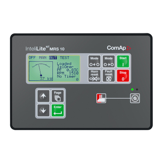
InteliLite
®
InteliLite
Modular Gen-set Controller
Compact Controller for Single Operating Gen-sets
(IL-CU MRS10/11/15/16 unit)
SW version 2.2, November 2004
Copyright © 2004 ComAp s.r.o.
Written by Adéla Klimentová
Prague, Czech Republic
MRS
ComAp, spol. s r.o.
Světova 7, 180 00 Praha 8, Czech Republic
Tel: +420 2 66316661, Fax: +420 2 66316647
E-mail: info@comap.cz, www.comap.cz
User guide
Advertisement
Table of Contents

Subscribe to Our Youtube Channel
Related Manuals for ComAp InteliLite MRS10


Summary of Contents for ComAp InteliLite MRS10
- Page 1 (IL-CU MRS10/11/15/16 unit) SW version 2.2, November 2004 User guide ComAp, spol. s r.o. Copyright © 2004 ComAp s.r.o. Světova 7, 180 00 Praha 8, Czech Republic Written by Adéla Klimentová Tel: +420 2 66316661, Fax: +420 2 66316647 Prague, Czech Republic...
-
Page 2: Table Of Contents
MEASUREMENT screens description ....................46 Chart guide to menus and pushbutton’s operation ................49 Function description ..........................50 OFF mode ............................50 MAN mode ............................50 AUT mode ............................51 InteliLite – MRS10/11/15/16, SW version 2.2, ©ComAp – November 2004 IL-MRS-2.2.pdf... - Page 3 Dimensions and weight ........................64 Generator ............................64 Binary inputs and outputs........................64 Analog inputs............................. 64 Speed pick-up input .......................... 65 *RS232 interface ..........................65 *CAN bus interface..........................65 InteliLite – MRS10/11/15/16, SW version 2.2, ©ComAp – November 2004 IL-MRS-2.2.pdf...
-
Page 4: General Guidelines
REMOTE START/STOP (Capital letters) binary inputs and outputs *Something (Symbol * before text) valid only for iL MRS 15/16 ^Something (Symbol ^ before text) valid only for iL MRS 11/16 InteliLite – MRS10/11/15/16, SW version 2.2, ©ComAp – November 2004 IL-MRS-2.2.pdf... - Page 5 Note: ComAp believes that all information provided herein is correct and reliable and reserves the right to update at any time. ComAp does not assume any responsibility for its use unless otherwise expressly undertaken. Note: SW and HW must be compatible (MRS10 firmware and MRS10 HW) otherwise the function wil be disabled.
-
Page 6: General Description
The module can be used especially for Pt100 sensors and current sensors. The module PTM is not suitable for VDO temperature sensor. See the documentation of iGS-PTM for the technical and function description. InteliLite – MRS10/11/15/16, SW version 2.2, ©ComAp – November 2004 IL-MRS-2.2.pdf... -
Page 7: Terminals And Dimensions
RPM Grounding Terminal Hint: EXTENSION MODULE and TEST PORT serves for Extension IGS-PTM or IG-IOM and IGL-RA15 CAN bus connection only. This port is used for production tests as well. InteliLite – MRS10/11/15/16, SW version 2.2, ©ComAp – November 2004 IL-MRS-2.2.pdf... -
Page 8: Dimensions
(4.4 x 6,9“) IL-MRS 10, 11 170 (8,87") 185 (7,3") Only for service purpose AT-LINK-CONV IL-MRS 15, 16 170 (8,87") 185 (7,3") Extension module via CAN bus RS 232 Cable InteliLite – MRS10/11/15/16, SW version 2.2, ©ComAp – November 2004 IL-MRS-2.2.pdf... -
Page 9: Recommended Wiring
Recommended wiring MRS – Wiring Diagram Hint: From IL-2.1 it is possible to start Volvo and Scania engines via CAN bus. See Engines started via bus. InteliLite – MRS10/11/15/16, SW version 2.2, ©ComAp – November 2004 IL-MRS-2.2.pdf... -
Page 10: Getting Started
Relays controller 12VDC Battery The capacitor size depends on required time. It shall be approximately thousands of microFarads. Or by connecting special I-LBA module: Relays controller 12VDC Battery InteliLite – MRS10/11/15/16, SW version 2.2, ©ComAp – November 2004 IL-MRS-2.2.pdf... - Page 11 Use as short as possible cable to the grounding point on the switchboard Use cable min. 2,5mm The “-“ terminal of the battery has to be properly grounded As short as possible InteliLite – MRS10/11/15/16, SW version 2.2, ©ComAp – November 2004 IL-MRS-2.2.pdf...
- Page 12 InteliLite – MRS10/11/15/16, SW version 2.2, ©ComAp – November 2004 IL-MRS-2.2.pdf...
- Page 13 Use cables of 2,5mm Use transformers to 5A Connect CT according to following drawings COM L1l Voltage measurement GENERATOR MAINS Hint: Switchboard lighting strikes protection according standard regulation is expected !!! InteliLite – MRS10/11/15/16, SW version 2.2, ©ComAp – November 2004 IL-MRS-2.2.pdf...
-
Page 14: Single Phase Applications
IL version 1.4 and lower.) Analog inputs Three analog inputs are available on the IL-CU Configuration Each analog input can be configured by LiteEdit software following way. InteliLite – MRS10/11/15/16, SW version 2.2, ©ComAp – November 2004 IL-MRS-2.2.pdf... - Page 15 User Curve A, B, C are adjustable in LiteEdit. Each Analog input has separate set points for two level alarm setting. Analog input alarm levels and delay adjust in Protection or Engine protection group. InteliLite – MRS10/11/15/16, SW version 2.2, ©ComAp – November 2004 IL-MRS-2.2.pdf...
- Page 16 As three state input Open, close and failure state are detected. Threshold level is 750 Ω, failure is detected when circuit resistance is <10 Ω or > 2400 Ω. InteliLite – MRS10/11/15/16, SW version 2.2, ©ComAp – November 2004 IL-MRS-2.2.pdf...
- Page 17 Analog input and COM terminal of Analog inputs Set to: VDO press Decimals: setting of number of decimal points of measured value. kPa, 100%, 50 °C „0“ - e.g. „1“ – e.g. InteliLite – MRS10/11/15/16, SW version 2.2, ©ComAp – November 2004 IL-MRS-2.2.pdf...
- Page 18 Number of decimal points of Wrn level1 and Sd level is the same as the configured number of decimal points of measured value. Binary inputs 4k7 Ω Power Supply Battery Binary outputs LOAD Power Supply Battery InteliLite – MRS10/11/15/16, SW version 2.2, ©ComAp – November 2004 IL-MRS-2.2.pdf...
-
Page 19: Extension Modules (Can Bus) Connection
IL-CU – IGS-PTM IL-CU – IGL-RA15 IL-CU – IG-IOM – IGL-RA15 IL-CU – IGS-PTM – IGL-RA15 It is possible to connect only one IG-IOM or IGS-PTM and one IGL-RA15 to IL-CU. InteliLite – MRS10/11/15/16, SW version 2.2, ©ComAp – November 2004 IL-MRS-2.2.pdf... -
Page 20: Inputs And Outputs
Emergency stop function it is recommended to connect separate circuit for disconnection of Fuel solenoid and Starter signals. Sprinkler If the input is closed all alarms are disabled except the binary input EMERGENCY STOP and "engine overspeed protection". InteliLite – MRS10/11/15/16, SW version 2.2, ©ComAp – November 2004 IL-MRS-2.2.pdf... - Page 21 Generator current and power measurement is active in this mode, regardless of the actual state of the engine. After the input is open again, the controller recovers to previous state and behaves according to the actual situation . InteliLite – MRS10/11/15/16, SW version 2.2, ©ComAp – November 2004 IL-MRS-2.2.pdf...
-
Page 22: Binary Outputs Il-Cu - Default
The output Idle/Nominal closes after the timer Idle time elapses. The Idle time counter starts to countdown when Start speed reached. The Underspeed protection is not evaluated during idle period. A Start fail protection occurs if the RPM drop below 2RPM during idle. InteliLite – MRS10/11/15/16, SW version 2.2, ©ComAp – November 2004 IL-MRS-2.2.pdf... - Page 23 • Max time of HORN is exceeded (Horn timeout) The output closes again if a new fault comes up. Ready The output is closed if following conditions are fulfilled: InteliLite – MRS10/11/15/16, SW version 2.2, ©ComAp – November 2004 IL-MRS-2.2.pdf...
- Page 24 The output opens, if • alarm is not active and • FAULT RESET is pressed Overspeed Output closes if the gen-set over speed alarm activates. The output opens, if InteliLite – MRS10/11/15/16, SW version 2.2, ©ComAp – November 2004 IL-MRS-2.2.pdf...
- Page 25 FAULT RESET is pressed Common Fls Output closes when any sensor fail alarm appears. The output opens, if • No warning alarm is active and • FAULT RESET is pressed InteliLite – MRS10/11/15/16, SW version 2.2, ©ComAp – November 2004 IL-MRS-2.2.pdf...
- Page 26 The outputs give an information about the assigned binary input. In case the assigned binary input is configured to alarm type, then the output closes when the alarm activates. It opens if • alarm is not active and InteliLite – MRS10/11/15/16, SW version 2.2, ©ComAp – November 2004 IL-MRS-2.2.pdf...
-
Page 27: Analog Inputs
Water temperature analog input. Default VDO sensor in range 0 to 100 °C. Fuel level Fuel level analog input. Default VDO sensor 0-180R = 0-100% Hint: For further information about analog inputs’ configuration see Analog inputs. InteliLite – MRS10/11/15/16, SW version 2.2, ©ComAp – November 2004 IL-MRS-2.2.pdf... -
Page 28: Setpoints
Nominal generator voltage (phase to neutral) Step: Range: 100 – 300 V Nominal freq [Hz] Nominal generator frequency (usually 50 or 60 Hz ) Step: Range: 45 – 65 Hz InteliLite – MRS10/11/15/16, SW version 2.2, ©ComAp – November 2004 IL-MRS-2.2.pdf... -
Page 29: Engine Params
Engine params Start RPM “Firing” speed when iL controller stops cranking (starter goes OFF). Step: 1% of nominal RPM Range: 5 – 50 % InteliLite – MRS10/11/15/16, SW version 2.2, ©ComAp – November 2004 IL-MRS-2.2.pdf... - Page 30 If the IDLE function not supported on the governor, set the Idle time nevertheless to minimum 5s to avoid Underspeed possibly caused by instability of the engine short after start. InteliLite – MRS10/11/15/16, SW version 2.2, ©ComAp – November 2004 IL-MRS-2.2.pdf...
- Page 31 The magnetization current is provided independently on this setpoint value. The D+ charge fail protection becomes active after Engine params:Idle time reaches zero. ECU FreqSelect [PRIMARY/SECONDARY/DEFAULT] This setpoint should be used only for Volvo and Scania engines. InteliLite – MRS10/11/15/16, SW version 2.2, ©ComAp – November 2004 IL-MRS-2.2.pdf...
-
Page 32: Engine Protect
Range: -100 – Anlinp2 level2 AnlInp2 level2 Shutdown threshold level for ANALOG INPUT 2 1 °C Step: Range: AnlInp2 level1 – 10000 AnlInp2 del Delay for ANALOG INPUT 2 alarm. Step: InteliLite – MRS10/11/15/16, SW version 2.2, ©ComAp – November 2004 IL-MRS-2.2.pdf... -
Page 33: Gener Protect
0 – 60.0 s Ishort [ % ] Shutdown occurs when short circuit limit Ishort limit is reached. Step: 1 % of Nominal current Range: 100 - 500 % InteliLite – MRS10/11/15/16, SW version 2.2, ©ComAp – November 2004 IL-MRS-2.2.pdf... - Page 34 No action 200 s 20 s Reaction time No action No action 200 s 20 s (time > 900 s) Maximal Reaction time 2Inom del Igen Nominal current Ishort InteliLite – MRS10/11/15/16, SW version 2.2, ©ComAp – November 2004 IL-MRS-2.2.pdf...
- Page 35 Shutdown level for generator underfrequency. Step: 0.1% of Nominal frequency Range: 0.0 – Gen >f Gen f del Delay for generator underfrequency and overfrequency alarm. Step: 0.1s Range: 0 – 60.0 s InteliLite – MRS10/11/15/16, SW version 2.2, ©ComAp – November 2004 IL-MRS-2.2.pdf...
-
Page 36: Sensor Spec
Range: -100 +10000 AnlInIOM2 del Delay for IOM ANALOG INPUT 2 alarm. Step: Range: AnlInIOM3 lev1 The level for IOM ANALOG INPUT 3 alarm detection. Step: Range: -100 +10000 InteliLite – MRS10/11/15/16, SW version 2.2, ©ComAp – November 2004 IL-MRS-2.2.pdf... - Page 37 CalibrAInIOM 1,2,3,4 […] Calibrating constant to adjust the measured value of IOM/PTM analog inputs. Physical dimension of calibrating constant is corresponding to Analog input. Step: Range: -1000 – +1000 InteliLite – MRS10/11/15/16, SW version 2.2, ©ComAp – November 2004 IL-MRS-2.2.pdf...
-
Page 38: Ecu-Controlled Engine Support
The output ECU PwrRelay closes at the beginning of prestart and opens if the engine shall be stopped. The engine is started via standard contact output or via CAN bus (for Volvo and Scania engines). For other engines J1939 is used for monitoring only. InteliLite – MRS10/11/15/16, SW version 2.2, ©ComAp – November 2004 IL-MRS-2.2.pdf... -
Page 39: Values Read From Ecu
InjectorCyl#5 SPN:656 InjectorCyl#6 SPN:677 EngStartRelay SPN:1485 ECU MainRelay For Scania Fault codes (FC) are displayed. Following messages are available for particular groups of Fault codes: FC:1000-1001 Overspeed FC:1100-1107 EngSpdSensor1 InteliLite – MRS10/11/15/16, SW version 2.2, ©ComAp – November 2004 IL-MRS-2.2.pdf... -
Page 40: Analog Inputs
IG-IOM/IGS-PTM module if connected. If the engine without ECU is controlled by InteliLite, the first analog input is permanently configured to Oil pressure, other analog inputs remain freely configurable. InteliLite – MRS10/11/15/16, SW version 2.2, ©ComAp – November 2004 IL-MRS-2.2.pdf... -
Page 41: J1939 Connection Description
1,10,15,33,34 powers up ECU and enables the injectors IL-CU CAN description Perkins Customer interface connector CAN bus common Screen for the J1939 cable. CAN bus H CAN bus L InteliLite – MRS10/11/15/16, SW version 2.2, ©ComAp – November 2004 IL-MRS-2.2.pdf... - Page 42 Cummins ISB 9 pin Deutsch connector CAN bus common SAE J1939 shield - screen for J1939 cable. CAN bus H SAE J1939 signal CAN bus L SAE J1939 return InteliLite – MRS10/11/15/16, SW version 2.2, ©ComAp – November 2004 IL-MRS-2.2.pdf...
-
Page 43: Sensor Specification
1117 1171 1232 1353 1309 1483 1347 1549 1385 1618 1423 1688 1461 1760 Hint: When measured value is 6% out of range the Sensor fail FLS is detected. InteliLite – MRS10/11/15/16, SW version 2.2, ©ComAp – November 2004 IL-MRS-2.2.pdf... -
Page 44: Operator Interface
(if an alarm is still active) or is off (if no alarm is active) 17. ^GCB ON: GREEN LED is on, if GCB is closed. Driven by GCB CLOSE/OPEN output. InteliLite – MRS10/11/15/16, SW version 2.2, ©ComAp – November 2004 IL-MRS-2.2.pdf... -
Page 45: How To Select The Gen-Set Mode
4) Application: MRS16 5) Branch: Standard Hint: Only in MEASUREMENT menu. How to find active alarms ? Active alarm list is the last screen in the MEASUREMENT menu. InteliLite – MRS10/11/15/16, SW version 2.2, ©ComAp – November 2004 IL-MRS-2.2.pdf... -
Page 46: Measurement Screens Description
5. RPM of the gen-set 6. Active power 7. Power factor 8. Timer - event s counting time (e.g. prestart, cooling, etc.) Generator screen Gen freq Gen V1-2, V2-3, V3-1 ph-ph InteliLite – MRS10/11/15/16, SW version 2.2, ©ComAp – November 2004 IL-MRS-2.2.pdf... - Page 47 (SPN, OC and FMI codes). If the verbal description of alarm is not available, the SPN (decimal and hexadecimal) is displayed. InteliLite – MRS10/11/15/16, SW version 2.2, ©ComAp – November 2004 IL-MRS-2.2.pdf...
- Page 48 EngOilPress BoostPress EngOilTemp 629(275h) Controller#1 EngCoolTemp _____________________ SPN:110 OC:7 FMI:3 Hint: For FMI = 0 and 1, WRN is displayed. For other FMI codes, FLS is displayed. Alarm list InteliLite – MRS10/11/15/16, SW version 2.2, ©ComAp – November 2004 IL-MRS-2.2.pdf...
-
Page 49: Chart Guide To Menus And Pushbutton's Operation
2. Press to editing mode ENTER 3. Adjust parameter by buttons Next 4. Press to write parameter into memory ENTER Screen Press to cancel of editing mode PAGE InteliLite – MRS10/11/15/16, SW version 2.2, ©ComAp – November 2004 IL-MRS-2.2.pdf... -
Page 50: Function Description
MaxCrank time counter started Cranking RPM> Start RPM STARTER off Starting PRESTART off D+ input activated or oil pressure detected STARTER off Cranking or Gen voltage > 25% Vgnom PRESTART off InteliLite – MRS10/11/15/16, SW version 2.2, ©ComAp – November 2004 IL-MRS-2.2.pdf... -
Page 51: Aut Mode
– for example in cold conditions). AUT mode The controller does not respond to buttons START, STOP, MCB ON/OFF, GCB ON/OFF. Engine start/stop request is given by binary input REM START/STOP. InteliLite – MRS10/11/15/16, SW version 2.2, ©ComAp – November 2004 IL-MRS-2.2.pdf... -
Page 52: Alarm Management
"A ll the tim e" c onfigured protec tions , I > , I > > , RP M > > , m ains failure detec tion InteliLite – MRS10/11/15/16, SW version 2.2, ©ComAp – November 2004 IL-MRS-2.2.pdf... -
Page 53: Voltage Phase Sequence Detection
Sensor fail Fls is detected when measured value is 6,2 percent out of range. Controller screen displays in this case string #### instead measured value. Sensor Range of measurement Sensor 100% Failure Failure Range of sensor InteliLite – MRS10/11/15/16, SW version 2.2, ©ComAp – November 2004 IL-MRS-2.2.pdf... -
Page 54: Gen-Set Operation States
Start failed Gen-set start failed. ParamFail NONE Wrong checksum of parameters. Happends InteliLite – MRS10/11/15/16, SW version 2.2, ©ComAp – November 2004 IL-MRS-2.2.pdf... - Page 55 Warning alarm in case of lost connection to IGL-RA15 module. *Sd IOM fail Shutdown alarm in case of lost connection to IG-IOM/IGS- PTM module. Wrn ECU Alarm ECU alarm list is not empty InteliLite – MRS10/11/15/16, SW version 2.2, ©ComAp – November 2004 IL-MRS-2.2.pdf...
-
Page 56: Remote Control And Data Logging
GND‘s Battery PC software - LiteEdit On the PC (for direct or modem connection) has to be installed the ComAp’s software package LiteEdit. (based on Windows 95 or newer platform) LiteEdit enables: read the quantities adjust all set points... - Page 57 30 Unsigned 8 Engine params Starting RPM 25 % 8254 50 Unsigned 8 Engine params Starting POil 4,5 Bar 9681 -10,0 1000,0 Integer 16 Engine params Prestart time 8394 600 Unsigned InteliLite – MRS10/11/15/16, SW version 2.2, ©ComAp – November 2004 IL-MRS-2.2.pdf...
- Page 58 8281 60,0 Unsigned Gener protect Ishort 250 % 8282 500 Unsigned Gener protect 2Inom del 4,0 s 8283 20,0 Unsigned Gener protect Curr unbal 50 % 8284 200 Unsigned InteliLite – MRS10/11/15/16, SW version 2.2, ©ComAp – November 2004 IL-MRS-2.2.pdf...
- Page 59 0 U6 8795 -1000 1000 Integer 16 module IOM/PTM CalibrAInIOM 4 0 U7 8796 -1000 1000 Integer 16 module Values (MRS10/11/15/16): Name Firmware ver. Application Date App. ver. Ser. num. InteliLite – MRS10/11/15/16, SW version 2.2, ©ComAp – November 2004 IL-MRS-2.2.pdf...
- Page 60 9628 Unsigned 16 Generator Gen V L2-L3 9629 Unsigned 16 Generator Gen V L3-L1 9630 Unsigned 16 Generator Gen curr L1 8198 Unsigned 16 Generator Gen curr L2 8199 Unsigned 16 InteliLite – MRS10/11/15/16, SW version 2.2, ©ComAp – November 2004 IL-MRS-2.2.pdf...
- Page 61 PercLoadAtCS 9925 Unsigned 8 In case of software malfunction DiagData shows the value that enables to locate possible bug in software. Include this number when reporting a software problem. InteliLite – MRS10/11/15/16, SW version 2.2, ©ComAp – November 2004 IL-MRS-2.2.pdf...
-
Page 62: Remote Communication
It is strongly recommended to use the same type of modem on the both sides (IL and PC) of connection. Analog Analog modem modem modem modem *Mobile SIM card setting Adjust SIM card in GSM modem following way: enable data connection (when required) no PIN code InteliLite – MRS10/11/15/16, SW version 2.2, ©ComAp – November 2004 IL-MRS-2.2.pdf... -
Page 63: Technical Data
+150 mA 36VDC 100 mA +20 mA +65 mA +100 mA InteliLite LT works immediately after switch on at -30 C and display becomes visible after a few minutes. InteliLite – MRS10/11/15/16, SW version 2.2, ©ComAp – November 2004 IL-MRS-2.2.pdf... -
Page 64: Dimensions And Weight
36 VDC Analog inputs Not electrically separated Resolution 10 bits 0 Ω -2,4 k Ω Sensor resistance range 4 % ± 2 Ω out of measured value Resistance measurement tolerance InteliLite – MRS10/11/15/16, SW version 2.2, ©ComAp – November 2004 IL-MRS-2.2.pdf... -
Page 65: Speed Pick-Up Input
3105A Paired EIA Industrial RS485 cable LAPP CABLE (see http://www.lappcable.com) • Unitronic BUS DeviceNet Trunk Cable • Unitronic BUS DeviceNet Drop Cable • Unitronic BUS CAN • Unitronic-FD BUS P CAN UL/CSA InteliLite – MRS10/11/15/16, SW version 2.2, ©ComAp – November 2004 IL-MRS-2.2.pdf...
Need help?
Do you have a question about the InteliLite MRS10 and is the answer not in the manual?
Questions and answers
My InteliLite MRS10 cranks once and goes off then a warning of maintenance comes on the screen
The ComAp InteliLite MRS10 shows a maintenance warning because the Maintenance Timer 3 setpoint has reached zero. This timer counts down while the engine is running, and when it reaches zero, the warning alarm Wrn Maintenance 3 is issued. The warning remains in the alarm list even if the controller is restarted until the setpoint is adjusted to a positive value.
This answer is automatically generated
@Mr. Anderson so how do I adjust the timer to a positive value
@Mr. Anderson i dont don't know if that's the reason my generator is not starting