Table of Contents
Advertisement
Quick Links
InteliLite 9
SW version 1.1.0
6 Communication
Copyright © 2018 ComAp a.s.
Written by Michal Slavata, Daniel Švanda
Prague, Czech Republic
ComAp a.s., U Uranie 1612/14a,
170 00 Prague 7, Czech Republic
Tel: +420 246 012 111
E-mail: info@comap-control.com, www.comap-control.com
Controller for single gen-set
Global Guide
applications
6
11
16
18
45
111
137
139
Advertisement
Table of Contents

Related Manuals for ComAp InteliLite 9


Summary of Contents for ComAp InteliLite 9
- Page 1 4 Installation and wiring 5 Controller setup 6 Communication 7 Technical data 8 Appendix Copyright © 2018 ComAp a.s. Written by Michal Slavata, Daniel Švanda Prague, Czech Republic ComAp a.s., U Uranie 1612/14a, 170 00 Prague 7, Czech Republic Global Guide Tel: +420 246 012 111 E-mail: info@comap-control.com, www.comap-control.com...
-
Page 2: Table Of Contents
1.5 Certifications and standards 1.6 Document history 1.7 Symbols in this manual 2 System overview 2.1 General description 2.1.1 The key features of InteliLite 9 2.2 True RMS measurement 2.3 Configurability and monitoring 2.3.1 Supported configuration and monitoring tools 2.3.2 Configuration parts 2.4 PC Tools... -
Page 3: Table Of Contents
5.2.2 RS232/RS485 5.2.3 Ethernet 5.3 Operator Guide 5.3.1 Front panel elements 5.3.2 Display screens and pages structure 5.3.3 Browsing alarms 5.3.4 Password 5.3.5 Information screen 5.3.6 Language selection 5.3.7 Display contrast adjustment 5.4 Functions 5.4.1 Start-stop sequence InteliLite 9 Global Guide... -
Page 4: Table Of Contents
6.1.2 Remote communication 6.2 Connection to 3rd party systems 6.2.1 MODBUS-RTU, MODBUS/TCP 7 Technical data 8 Appendix 8.1 Controller objects 8.1.1 Setpoints 8.1.2 Values 8.1.3 Logical binary inputs 8.1.4 Logical binary outputs 8.1.5 Logical analog inputs 8.2 Alarms InteliLite 9 Global Guide... -
Page 5: Table Of Contents
8.2.1 Alarms level 1 8.2.2 Alarms level 2 8.2.3 Fail sensor and other types 8.3 Modules 8.3.1 Plug-In modules InteliLite 9 Global Guide... -
Page 6: Table Of Contents
AGREEMENT CONDITIONS – COMAP CONTROL SYSTEMS SOFTWARE” (License Agreement) and/or in the “ComAp a.s. Global terms and conditions for sale of Products and provision of Services” (Terms) and/or in the “Standardní podmínky projektů komplexního řešení ke smlouvě o dílo, Standard Conditions for Supply of Complete Solutions”... - Page 7 Official version of the ComAp’s End User's Guide/Manual is the version published in English. ComAp reserves the right to update this End User's Guide/Manual at any time. ComAp does not assume any responsibility for its use outside of the scope of the Terms or the Conditions and the License Agreement.
-
Page 8: General Warnings
IMPORTANT: Be aware that the binary outputs can change state during and after software reprogramming (before the controller is used again ensure that the proper configuration and setpoint settings are set in the controller). InteliLite 9 Global Guide... -
Page 9: Certifications And Standards
EN 60068-2-27 (a=500 m/s ; T=6 ms) EN 60068-2-30:2005 25/55°C, RH 95%, 48hours EN 60529 (front panel IP65, back side IP20) 1.6 Document history Revision number Related sw. version Date Author 1.1.0 12.9.2018 Michal Slavata 1.0.0 2.11.2017 Daniel Švanda InteliLite 9 Global Guide... -
Page 10: Symbols In This Manual
Wifi / WAN / Passive Fuel current solenoid Breaker sensor 6 back to Document information Fuse Pick - up Breaker Fuse switch Relay coil Capacitor Relay coil of Generator slow- Coil operating Generator Resistor Connector - schematic female InteliLite 9 Global Guide... -
Page 11: System Overview
6 back to Table of contents 2.1 General description InteliLite 9 Family controllers are comprehensive gen-set controllers for single gen-sets operating in stand-by (MRS) or back-up (AMF) applications. A modular construction allows upgrades to different levels of complexity in order to provide the best solution for various customer applications. The controllers are equipped with a powerful graphic display showing icons, symbols and bar graphs for intuitive operation, which, together with its high level of functionality, sets new standards in Gen-set controls. -
Page 12: Supported Configuration And Monitoring Tools
The controller is shipped with a default configuration, which should be suitable for most standard applications. This default configuration can be changed only by using a PC with the InteliConfig software. See InteliConfig documentation for details. InteliLite 9 Global Guide... -
Page 13: Pc Tools
Special graphical controller monitoring software used mainly for commissioning and gen-set troubleshooting. See more in the WinScope Reference guide. This tool provides the following functions: Monitoring and archiving of ComAp controller’s parameters and values View of actual / historical trends in controller On-line change of controllers’... -
Page 14: Plug-In Modules
Band 2, Band 3, Band 4, Band 5, Band 7, Band 8, Band 20, all bands with diversity, WCDMA/HSDPA/HSUPA/HSPA+: Band 1, Band 2, Band 5, Band 8, all bands with diversity GPRS multi-slot class 10 TCP/IP communication over GPRS InteliLite 9 Global Guide... -
Page 15: Cm-Gprs
Communication module with two communication ports. RS232 and RS485 interface MODBUS Serial connection to InteliConfig 2.5.5 EM-BIO8-EFCP Hybrid current input and binary input/output extension module. Up to 8 additional configurable binary inputs or outputs 6 back to System overview InteliLite 9 Global Guide... -
Page 16: Applications Overview
3.2 MRS - Manual Remote Start The typical scheme of Manual Remote Start application is shown below. The controller controls one breaker – a generator breaker. Feedback from breaker isn’t necessary. InteliLite controllers can also work without breaker feedback. InteliLite 9 Global Guide... - Page 17 Image 3.2 MRS application overview 6 back to Applications overview InteliLite 9 Global Guide...
-
Page 18: Installation And Wiring
Terminal blocks Note: The package does not contain a communication or extension modules. The required modules should be ordered separately. 4.2 Controller installation 4.2.1 Dimensions Note: Dimension x depends on plug-in module Note: Dimensions are in millimeters InteliLite 9 Global Guide... -
Page 19: Mounting
0.15 N·m. Panel door mounting Note: Enclosure Type rating with mounting instruction - For use on a Flat surface of a type 1 enclosure. InteliLite 9 Global Guide... -
Page 20: Terminal Diagram
BOUT2 BIN1 CAN H BOUT3 BIN2 BOUT4 BIN3 BOUT5 BIN4 BOUT6 BIN5 BIN6 Image 4.1 Terminal diagram for InteliLite 9 9 ⑤ ANALOG INPUTS ⑥ GENERATOR ⑦ GENERATOR ⑧ MAINS VOLTAGE CURRENT VOLTAGE MEASUREMENT MEASUREMENT MEASUREMENT AIN COM AIN1 AIN2... -
Page 21: Recommended Wiring
Voltage measurement MRS wiring (page 28) Mains voltage inputs 61 - 67 Voltage measurement AMF wiring (page 26) USB (page 40) Note: Wiring terminal markings to included tightening torque: 0,5 N-m (4,5 lb-in)., and wire size: 2 mm (12- 26AWG). InteliLite 9 Global Guide... -
Page 22: General
If the voltage dip goes during cranking to 0 V and after 50 ms it recovers to 4 V, the controller continues operating. This cycle can repeat several times. During this voltage dip the controller screen backlight can turn off. InteliLite 9 Global Guide... -
Page 23: Measurement Wiring
147), Nominal Voltage Ph-N (page 149), Nominal Voltage Ph-Ph (page 149), Nominal Current (page 146), PT Ratio (page 149), Vm PT Ratio (page 150) CT Ratio (page 147) by appropriate setpoints in the Basic Settings group. InteliLite 9 Global Guide... - Page 24 Generator currents and power measurement is suppressed if current level is bellow <1 % of CT range. To ensure proper function: Use cables of 2.5 mm Use transformers to 5 A Connect CT according to following drawings: InteliLite 9 Global Guide...
- Page 25 ± 2 V. Therefore is strongly recommended to interconnect these two terminals together. Split phase application: Image 4.4 Split phase application IMPORTANT: The second phase of split phase connection is connected to the terminal, where is normally connected the third phase. InteliLite 9 Global Guide...
- Page 26 The generator protections are evaluated from different voltages based on Connection type (page 147) setting: 3Ph 4W – Ph-Ph voltage, Ph-N voltage 3Ph 3W – Ph-Ph voltage Split Ph – Ph-N voltage Mono Ph – Ph-N voltage InteliLite 9 Global Guide...
- Page 27 ConnectionType: 3 Phase 4 Wires Image 4.6 3 phase application with neutral ConnectionType: 3 Phase 3 Wires Image 4.7 3 phase application without neutral InteliLite 9 Global Guide...
- Page 28 Note: For fusing of voltage measurement input use T1A or T2A fuse. The generator protections are evaluated from different voltages based on Connection type (page 147) setting: 3Ph 4W – Ph-Ph voltage, Ph-N voltage 3Ph 3W – Ph-Ph voltage InteliLite 9 Global Guide...
- Page 29 Split Ph – Ph-N voltage Mono Ph – Ph-N voltage ConnectionType: 3 Phase 4 Wires Image 4.10 3 phase application with neutral ConnectionType: 3 Phase 3 Wires Image 4.11 3 phase application without neutral InteliLite 9 Global Guide...
-
Page 30: Magnetic Pick-Up
A magnetic speed sensor (pickup) is the most common method of engine speed measurement. To use this method, mount the pickup opposite to the engine flywheel, connect the cable to the controller as shown on the InteliLite 9 Global Guide... - Page 31 (Gear Teeth = 0). Controller is measuring some voltage value on input terminals due to open fusing. If RPM > 0 the controller will be put into a Not ready state and the engine will not be allowed to start. InteliLite 9 Global Guide...
-
Page 32: Binary Inputs
4.4.6 Binary inputs Use minimally 1 mm cables for wiring of Binary inputs. Image 4.14 Wiring binary inputs Note: The name and function or alarm type for each binary input have to be assigned during the configuration. InteliLite 9 Global Guide... -
Page 33: Binary Outputs
Note: Binary output 1 (terminal 4) and binary output 2 (terminal 5) are high current outputs (5 A for long term). IMPORTANT: When operating temperature is higher than 60 °C it is strongly recommended to limit output current of high current binary outputs (terminal 4 and terminal 5) to 4 A (each). InteliLite 9 Global Guide... -
Page 34: E-Stop
In the case of grounded sensors, connect the AI COM terminal to the engine body as near to the sensors as possible. In the case of isolated sensors, connect the AI COM terminal to the negative power supply terminal of the controller as well as one pole of each sensor. InteliLite 9 Global Guide... - Page 35 On each analog input, there is a possibility to connect voltage or current output sensor instead of resistive one. Recommended wiring connection for these measurements and recommended curves are bellow. Voltage sensors Sensor’s output R1 (Ω) R2 (Ω) range (V) 0 - 10 0 - 30 1500 0 - 70 3300 InteliLite 9 Global Guide...
- Page 36 Note: This is a conversion of voltage from voltage sensor to appropriate resistance value. Use resistance values in InteliConfig to create your specific curve. These values should be used in "Ohm" column. Current sensors Sensor’s output R (Ω) range (mA) 0-20 InteliLite 9 Global Guide...
- Page 37 1666 1914 2222 2596 Note: This is a conversion of current from current sensor to appropriate resistance value. Use resistance values in InteliConfig to create your specific curve. These values should be used in "Ohm" column. InteliLite 9 Global Guide...
-
Page 38: Can Bus
The CAN bus has to be terminated by 120 Ohm resistors at both ends use a cable with following parameters: Recommended data cables: BELDEN (http://www.belden.com) - for shorter distances: 3105A Paired - EIA Industrial RS-485 PLTC/CM (1x2 conductors); for longer distances: 3106A Paired - EIA Industrial RS-485 PLTC/CM (1x2+1 conductors) InteliLite 9 Global Guide... - Page 39 Note: A termination resistor at the CAN (120Ω) is already implemented on the PCB. For connecting, close the jumper near the appropriate CAN terminal. Image 4.22 CAN bus topology For shorter distances (connection within one building) Image 4.23 CAN bus wiring for shorter distances InteliLite 9 Global Guide...
- Page 40 IMPORTANT: Power supply by USB is only for service purpose. Binary inputs and outputs are in logical 0. Also plug-in modules are not working. Protections recommended: Phoenix Contact (http://www.phoenixcontact.com): PT 5-HF-12DC-ST with PT2x2- BE (base element) or Saltek (http://www.saltek.cz): DM-012/2 R DJ InteliLite 9 Global Guide...
-
Page 41: Example Of Amf Wiring
4.4.12 Example of AMF Wiring InteliLite 9 Global Guide... -
Page 42: Example Of Mrs Wiring
4.4.13 Example of MRS Wiring InteliLite 9 Global Guide... -
Page 43: Plug-In Module Installation
After removing back cover insert the plug-in module. Plug-in module has to be inserted under holders. Start with holders marked by symbol 1. On the controller are also arrows for better navigation. After inserting plug-in module under holders 1 press it down to holders marked by symbol 2 which locks the module. InteliLite 9 Global Guide... - Page 44 After locking the plug-in module into holders, place back the back cover (small cover for connectors has to be removed from back cover). Finally insert the small cover for connectors. Small covers are unique for each plug- in module. 6 back to Installation and wiring InteliLite 9 Global Guide...
-
Page 45: Controller Setup
Switch controller to OFF mode OFF ( 311) EMOTE PAGE BOUT4 Switch controller to AUTO mode AUTO ( 310) EMOTE PAGE BOUT5 Suppression of alarms 313) VERRIDE PAGE BOUT6 Binary input function used as alarm BIN P 296) ROTECTION PAGE InteliLite 9 Global Guide... -
Page 46: Binary Outputs Mrs
PC tools to the controller. If you require detailed information on each PC tool please use the included Help in those PC tools or download their Reference Guides. 5.2.1 USB You may connect to the controller using the USB port. In this case standard USB A to B cable should be used. InteliLite 9 Global Guide... -
Page 47: Rs232/Rs485
RS232/RS485 converter may be used). The following settings need to be checked in the controller: COM1 Mode (page 221) = Direct Controller Address (page 154) has to be set to the same value as in the PC tool InteliLite 9 Global Guide... - Page 48 Connection using InteliConfig Image 5.4 First screen of InteliConfig - select connect to controller Image 5.5 Second screen of InteliConfig - select Serial link InteliLite 9 Global Guide...
-
Page 49: Ethernet
Gateway IP (page 237) can be set here when it is used Connection using InteliConfig Image 5.7 First screen of InteliConfig - select connect to controller InteliLite 9 Global Guide... -
Page 50: Operator Guide
Image 5.8 Second screen of InteliConfig - select Internet/Ethernet Connection using WinScope Image 5.9 WinScope screen 5.3 Operator Guide 5.3.1 Front panel elements 5.3.2 Display screens and pages structure 5.3.3 Browsing alarms 5.3.4 Password InteliLite 9 Global Guide... -
Page 51: Front Panel Elements
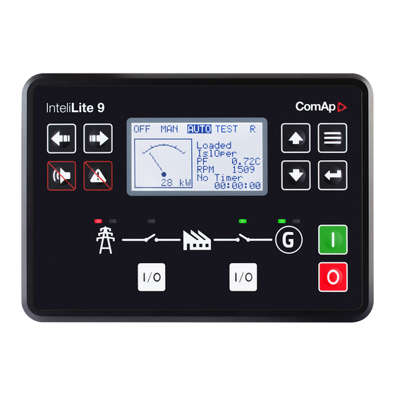
5.3.5 Information screen 5.3.6 Language selection 5.3.7 Display contrast adjustment 5.3.1 Front panel elements Image 5.10 Operator interface of InteliLite 9 Control buttons Position Picture Description LEFT button. Use this button to move left or to change the mode. The button can change the mode only if the main screen with the indicator of currently selected mode is displayed. -
Page 52: Display Screens And Pages Structure
MCB ON. Green LED is on if MCB is closed. It is driven by MCB CLOSE/OPEN output or by MCB feedback signal. 5.3.2 Display screens and pages structure The displayed information is structured into "pages" and "screens". Use PAGE button to switch over the pages. InteliLite 9 Global Guide... - Page 53 CCESS R - active when there is active remote connection to controller Exclamation mark - active when there is any alarm in alarmlist Measurement Screens Note: Use Up and Down button to move between measurement pages. InteliLite 9 Global Guide...
- Page 54 Note: Use Up and Down button to move between measurement pages. Note: Use Up and Down button to move between measurement pages. Note: Use Up and Down button to move between measurement pages. Note: Use Up and Down button to move between measurement pages. InteliLite 9 Global Guide...
- Page 55 Note: Use Up and Down button to move between measurement pages. Note: Use Up and Down button to move between measurement pages. Note: Use Up and Down button to move between measurement pages. Note: Use Up and Down button to move between measurement pages. InteliLite 9 Global Guide...
- Page 56 Note: Use Up and Down button to move between measurement pages. Note: Use Up and Down button to move between measurement pages. Note: Use Up and Down button to move between measurement pages. Note: Use Up and Down button to move between measurement pages. InteliLite 9 Global Guide...
- Page 57 Note: Use Up and Down button to move between measurement pages. Note: Use Up and Down button to move between measurement pages. Note: Use Up and Down button to move between measurement pages. Note: Use Up and Down button to move between measurement pages. InteliLite 9 Global Guide...
- Page 58 Note: Use Up and Down button to move between measurement pages. Note: Use Up and Down button to move between measurement pages. Note: Use Up and Down button to move between measurement pages. Note: Use Up and Down button to move between measurement pages. InteliLite 9 Global Guide...
- Page 59 Note: There can be some additional screens and also some screens can be hidden. Screen’s visibility depends on actual configuration (usage of extension or communication modules, ECU, etc.). Setpoint Screens Note: From all measurement pages we can fluently go to the setpoint group page by pressing Page button. InteliLite 9 Global Guide...
- Page 60 Note: Use Page button to discard changes, to set setpoint to previous value and to return to the list of setpoints of selected group. IMPORTANT: Cannot change setpoint? Setpoints marked with an padlock are password protected. Enter password as described in the chapter Password (page 66). InteliLite 9 Global Guide...
- Page 61 Note: Use Enter button to move to the next page of history log. Note: Use Up and Down button to select required alarm reason. Note: Use Enter button to move to the next page of history log. InteliLite 9 Global Guide...
- Page 62 Note: Use Enter button to move to the next page of history log. Note: Use Up and Down button to select required alarm reason. Note: Use Enter button to move to the next page of history log. InteliLite 9 Global Guide...
- Page 63 Note: Use Enter button to move to the next page of history log. Note: Use Up and Down button to select required alarm reason. Note: Use Enter button to move to the next page of history log. InteliLite 9 Global Guide...
- Page 64 Note: Use Enter button to move to the next page of history log. Note: Use Up and Down button to select required alarm reason. Note: Use Enter button to move to the first page of history log. InteliLite 9 Global Guide...
-
Page 65: Browsing Alarms
Not confirmed alarms are displayed with an asterisk. It means the alarm is still not acknowledged (confirmed). ECU alarms: SPN/FMI/OC/SC SPN - Suspect parameter number FMI - type of protection OC - number of errors SC - source of error InteliLite 9 Global Guide... -
Page 66: Password
Note: From all measurement pages we can fluently go to the setpoint group page by pressing Page button. Note: Use Up and Down button to select setpoint group Password. Note: Use Enter button to enter setpoint group Password. InteliLite 9 Global Guide... - Page 67 Note: Use Enter button to confirm the password or Page button to cancel entering the password. Note: In case that invalid password is entered, the controller shows Invalid password screen. Use Page button to go back to menu. InteliLite 9 Global Guide...
- Page 68 Note: Use Up and Down button to select Change Password. Note: Use Enter button to enter selected setpoint. Note: Use Up and Down button to select required level of password. Note: Use Enter button to enter selected setpoint. InteliLite 9 Global Guide...
- Page 69 Note: Before changing the password controller has to be unlocked. In case that controller is locked, the controller shows Password required screen. In that case the password has to be entered before changing the password. InteliLite 9 Global Guide...
- Page 70 Note: Use Up and Down button to select setpoint group Password. Note: Use Enter button to enter setpoint group Password. Note: Use Up and Down button to select Enter Password. Note: Use Enter button to enter selected setpoint. InteliLite 9 Global Guide...
- Page 71 4. Each further attempt to enter invalid password will double the blocking time, but maximum blocking time is 20 minutes. 5. When incorrect password is entered 100-times after each other the controller is blocked forever and the password reset procedure is required to unblock it. InteliLite 9 Global Guide...
-
Page 72: Information Screen
Note: On Main measurement screen press Enter and Page button together. Enter button has to be pressed first. Note: Use Page button to move to the next page. Note: Use Page button to move to the next page. Note: Use Up button to move back to main measurement screen. InteliLite 9 Global Guide... -
Page 73: Language Selection
Note: On Main measurement screen press Enter and Page button together. Enter button has to be pressed first. Note: Use Page button to move to the next page. Note: Use Page button to move to the next page. Note: Use Page button to move to the next page. InteliLite 9 Global Guide... -
Page 74: Display Contrast Adjustment
Up button together for higher contrast. Note: After setting a contrast, no another action is needed. 6 back to Controller setup 5.4 Functions 5.4.1 Start-stop sequence 5.4.2 AMF sequence 5.4.3 Operating Modes 5.4.4 Engine start 5.4.5 Stabilization 5.4.6 Connecting to load InteliLite 9 Global Guide... -
Page 75: Start-Stop Sequence
Cranking Time (page 160) counter started Cranking RPM > Starting RPM 344) off, Starting TARTER PAGE RESTART 341) PAGE D+ input activated or oil pressure 344) off, Cranking TARTER PAGE RESTART detected or Generator voltage > 341) PAGE InteliLite 9 Global Guide... - Page 76 PAGE Stop RPM = 0, Oil pressure not Ready detected, Generator voltage < 10V, D+ not active If at least one of engine running Stop (Stop indication is detected when Stop fail) Time (page 176) elapsed. InteliLite 9 Global Guide...
-
Page 77: Amf Sequence
MCB Opens On (page 207) setpoint) and start-up sequence is interrupted. Note: If mains fails during stop procedure (cooling) again, stop sequence is interrupted, MCB opened and GCB Transfer Delay (page 201). re-closed with InteliLite 9 Global Guide... -
Page 78: Operating Modes
Note: When the AMF function will start the engine than the engine will be running at least for the time which is defined in Mains Return Delay (page 200) setpoint, even if the mains would return in the meantime. InteliLite 9 Global Guide... -
Page 79: Engine Start
(as it was during the start). The idle period duration is adjusted by the setpoint Idle Time (page 172). After the idle period has finished, the output 335) is activated and the start-up OMINAL PAGE sequence is finished. The Stabilization (page 81) phase follows. InteliLite 9 Global Guide... - Page 80 Image 5.11 Flowchart of start of diesel engine InteliLite 9 Global Guide...
-
Page 81: Stabilization
The “AMF function” represents the automatic start in the event that the mains have failed and stop after the mains have been restored. The automatic start can be enabled or disabled by binary inputs AMF S TART LOCK InteliLite 9 Global Guide... -
Page 82: Engine Cool Down And Stop
201). After GCB is opened, the gen-set cools down and a stop. IMPORTANT: Controller has this behavior only in AUTO mode! 5.4.9 Engine cool down and stop The cool down phase follows after the stop command has been issued and the GCB has been opened. InteliLite 9 Global Guide... -
Page 83: Alarm Management
Each alarm is written to the Alarmlist (page 87). Each alarm causes a record to be written into the history log. Each alarm activates the Alarm and Horn output. Each alarm can cause sending of a SMS message or an email. InteliLite 9 Global Guide... - Page 84 VERRIDE PAGE engine. This input may be used in situations where providing the power is extremely important – e.g. if the gen- set drives pumps for fire extinguishers (sprinklers). InteliLite 9 Global Guide...
- Page 85 Also GCB breaker is open. The gen-set cannot be started again while there is a shutdown alarm in the alarmlist. Activates the output AL C 318) as well as the standard alarm OMMON PAGE outputs 334) 322)). PAGE LARM PAGE InteliLite 9 Global Guide...
- Page 86 Sd Messages (page 233) to ON. Also enter a valid GSM phone number or email address to the setpoints Telephone Number 1 (page 230), Email Address 1 (page 231) The list of all supported terminals shows the table below: InteliLite 9 Global Guide...
- Page 87 Analog Protection 2 Value measured on analog input 2 is </> than Analog Input 2 Wrn Wrn (page 209) setpoint. Analog Protection 2 Sd Analog Input 2 Sd Value measured on analog input 2 is </> than InteliLite 9 Global Guide...
- Page 88 (like oil pressure or D+) and at Measurement Fail the end of timer Maximum Cranking Time (page 160) there are no RPMs > Starting RPM (page 161) detected. Wrn Stop Fail Gen-set stop failed. See description at Gen-set Operation States InteliLite 9 Global Guide...
-
Page 89: History Log
Reason for history record (any event or alarm related to the gen-set Time Time Time Date Date Date Engine rotations per minute Power Generator active power Reactive power Generator reactive power Power Factor Generator power factor Load Character LChr Generator load character Generator Gfrq Generator Frequency InteliLite 9 Global Guide... -
Page 90: Breaker Control
The breaker must respond within max. 5 seconds to a close and open command. Special attention should be paid to opening of motorized circuit breakers, as it could take more than 5 seconds on some types. In such cases it is necessary to use an undervoltage coil for fast opening. InteliLite 9 Global Guide... - Page 91 If a contactor is used on the MCB position, it will open itself immediately after the mains have failed, because it will lose power for the coil. That is why the following adjustment is necessary to prevent triggering InteliLite 9 Global Guide...
- Page 92 Image 5.16 Breaker fail - breaker close/open in steady position - open Image 5.17 Breaker fail - breaker close/open in steady position - close When binary output breaker close/open opens there is 2 sec delay for breaker fail detection. InteliLite 9 Global Guide...
-
Page 93: Exercise Timer
Timer 1 First Occur. Time (page 216) Timer 1 Repeat Week In Month (page 221) Timer 1 Duration (page 216) Timer 1 Refresh Period (page 218) Timer 1 Repeated (page 217) Timer 1 Weekends (page 219) Timer 1 Repeat Day (page 220) InteliLite 9 Global Guide... - Page 94 Timer 1 Function (page 214) In controller go to the Scheduler setpoint group. Select the function of timer via Timer 1 Repetition (page 215) setpoint. Than go to Timer 1 Setup and press enter button. In setpoint select Once InteliLite 9 Global Guide...
- Page 95 Daily and adjust Timer 1 Refresh Period (page 218) (x-th day of repetition) and Timer 1 Weekends (page 219) (behavior of timer on weekends). Note: Use left and right buttons to move between timer setpoints. InteliLite 9 Global Guide...
- Page 96 To set-up timer via InteliConfig go to the setpoint ribbon, setpoint group scheduler and setpoint Timer 1 Setup. Note: First of all function of timer has to be adjusted via setpoint Timer 1 Function (page 214). InteliLite 9 Global Guide...
- Page 97 Example: On image example first start of timer will be 1/1/2016 at 12:00. Duration will be 1 hour. Timer will be again activated every 2nd day in 2nd month at 12:00 for 1 hour. InteliLite 9 Global Guide...
- Page 98 1 Repeated Day In Week (page 220) (days in week when timer is active) and Timer 1 Repeat Week In Month (page 221) (concrete week in repeated months). Note: Use left and right buttons to move between timer setpoints. InteliLite 9 Global Guide...
-
Page 99: Service Timers
Service timers are used as maintenance interval counters. Counters can be set by setpoints - Maintenance Timer 1 (page 187), Maintenance Timer 2 (page 187) Maintenance Timer 3 (page 188). All of them work the same way - their values are decremented every hour when the gen-set is running. InteliLite 9 Global Guide... - Page 100 Wrn Maintenance 1 (page 365) Wrn Maintenance 2 (page 366) Wrn Maintenance 3 (page 366) is active until the respective counter is readjusted back to nonzero value. Unused timer has to be adjusted to maximal value 10000 (OFF). InteliLite 9 Global Guide...
-
Page 101: Flowchart
5.4.15 Flowchart Image 5.26 Basic flowchart of controller sequences InteliLite 9 Global Guide... -
Page 102: Additional Running Engine Indications
Pause between start attempts. Starting Starting speed is reached and the Idle timer is running. Running Gen-set is running at nominal speed. Loaded Gen-set is running at nominal speed and GCB C 327) is closed. LOSE PAGE InteliLite 9 Global Guide... - Page 103 RPM, there is no delay. Stop engine conditions If no engine running conditions are validated than the controller will wait extra 12 s before leaving the Machine state Stop and than it will release the 345) output. OLENOID PAGE InteliLite 9 Global Guide...
- Page 104 Mains is present and all its values are within limits. MainsOper Example: MCB is closed, GCB is opened MainsFlt Mains fails Island operation IslOper Example: MCB is opened, GCB is closed MainsRet Mains recover BrksOff GCB, MCB opened InteliLite 9 Global Guide...
-
Page 105: Sensor Curves
Tier 4 Final support generally provides monitoring and control of after-treatment system installed on generators engine. The requirements are defined as: Providing After-Treatment status information by displaying universal lamps (icons) displaying analog and binary values Control of After-Treatment regeneration function by transmitting commands to the ECU InteliLite 9 Global Guide... - Page 106 Image 5.30 Example of inactive Tier 4 Final screen Universal lamps (icons) Universal lamp icons are shown on the After-Treatment screen. Based on specific value read in specific frame with specific SPN is every lamp icon either: shown hidden InteliLite 9 Global Guide...
- Page 107 Note: DPF = Diesel Particulate Filter; SCR = Selective Catalytic DPF/SCR lamp command Reduction. This lamp also activates alarm After- Treatment (page 368). Note: This lamp also Exhaust system high temperature activates alarm After- lamp command Treatment (page 368). InteliLite 9 Global Guide...
-
Page 108: Alternate Configuration
User can force or inhibit regeneration process by activating appropriate binary inputs of the controller. Please see the list of binary inputs below: 305) ORCE EGENERATION PAGE 310) EGENERATION NHIBIT PAGE 5.4.21 Alternate configuration In controller are 3 sets of configuration. InteliLite 9 Global Guide... - Page 109 There is a measuring of E-STOP input voltage analogically and setting the binary value (representing emergency stop input level) based on comparison of the measured voltage to two analog levels, which are derived from the controller supply voltage (battery voltage) perceptually. InteliLite 9 Global Guide...
-
Page 110: Ecu Frequency Selection
PAGE Note: If LBO ECU P 324) is used, this change can be make only in prestart phase. So OWER ELAY PAGE prestart has to be set up for enough long time. 6 back to Functions InteliLite 9 Global Guide... -
Page 111: Communication
Note: Also USB-RS232 convertor can be used. Image 6.1 Cross-wired RS232 cable is used Image 6.2 Cross-wired RS232 cable and USB is used Connection via RS485 A plug-in communication module CM-RS232-485 is necessary for communication via RS485 connection. InteliLite 9 Global Guide... - Page 112 PC tool. Image 6.4 Ethernet cable is used Connection via USB USB interface uses HID profile. Image 6.5 Shielded USB type A cable is used 6 back to Communication InteliLite 9 Global Guide...
-
Page 113: Remote Communication
Next way is to switch the CM-Ethernet to automatic IP address mode. Adjust the setpoint IP Address Mode (page 235) to AUTOMATIC. In that case all IP settings are assigned by DHCP server. Then configure the InteliLite 9 Global Guide... - Page 114 IP address of the network gateway to the local IP address of CM- Ethernet at the port specified for ComAp protocol. Different port numbers can be used to create multiple port forwarding rules in the same local network.
- Page 115 Load on Mains hh:mm:ss AMF Stop Alarm SMS The InteliLite 9 controller equipped with the CM-GPRS or CM-4G-GPS communication module is able to send Alarm SMS according to the setting of setpoints: Wrn Message (page 233) BOC Message (page 233)
- Page 116 Get a list of available SMS requests. Note: Between commands are internal delays adjusted due to system requirements. Example: When the controller, in AUTO mode, with a controller name of “InteliLite 9-Test”, with the CM- GPRS module and access code “0” receives the SMS: 0 man, start, gcb close, gcb open, stop, auto Controller mode will be changed to MANUAL mode.
- Page 117 Event 1 hh:mm:ss Event 2 hh:mm:ss Event 3 Alarm Email The InteliLite 9 controller equipped with the CM-Ethernet communication module is able to send Alarm Emails according to the setting of setpoints: Wrn Message (page 233) BOC Message (page 233)
- Page 118 Alarm 2 Alarm 3 History events ----------------------------------------------- 0 dd/mm/yyyy hh:mm:ss.0 Event 1 -1 dd/mm/yyyy hh:mm:ss.0 Event 2 -2 dd/mm/yyyy hh:mm:ss.0 Event 3 Note: Asterisk means that alarm is unconfirmed and exclamation mark means that alarm is active. InteliLite 9 Global Guide...
- Page 119 Note: Only two remote clients can be connected to the Web Server at one moment. If you close your web browser without disconnecting from the CM-Ethernet ("Exit" button at the web pages), the connection will be blocked for next 5 minutes. Image 6.7 Web Server main screen InteliLite 9 Global Guide...
- Page 120 Click to the SCADA link in the toolbar to display the scada page. The scada page is also the main page which is displayed by default if you just put the CM-Ethernet address into the browser (after entering the right access code). Image 6.8 Web Server - Scada screen InteliLite 9 Global Guide...
- Page 121 Note: The measurement page is automatically refreshed every 60 seconds (this time cannot be changed). Image 6.9 Web Server - measurement screen InteliLite 9 Global Guide...
- Page 122 "Controller password" icon located in the toolbar and then enter valid password. Image 6.10 Web Server - Setpoints screen InteliLite 9 Global Guide...
- Page 123 Note: The history page is automatically refreshed every 60 seconds. If a new record appears in the controller, the web page will not show it immediately as e.g. InteliConfig. Image 6.11 Web Server - History screen InteliLite 9 Global Guide...
-
Page 124: Connection To 3Rd Party Systems
Modbus position. The serial speed for MODBUS-RTU communication is to be adjusted by the setpoint COM1 MODBUS Communication Speed (page 222) COM2 MODBUS Communication Speed (page 224). InteliLite 9 Global Guide... - Page 125 LSB = value MSB = value, MSB Integer16 2-byte signed integer LSB = value, LSB MSB = value, MSB Unsigned16 2-byte unsigned integer LSB = value, LSB Integer32 4-byte signed integer MSB1 = value, byte 3 (MSB) InteliLite 9 Global Guide...
- Page 126 MSB1 = ASCII value of the 1. character LSB1 = ASCII value of the 2. character Zero-terminated string of LongStr MSB2 = ASCII value of the 3. character max 31 ASCII characters. LSB2 = ASCII value of the 4. character … InteliLite 9 Global Guide...
- Page 127 04 – device error is returned in all other errorneous situations. More detailed specification of the problem can be consequently obtained by reading the registers 4205 – 4206. Reserved registers There are several registers with specific meaning. These registers are available in all controllers regardless of the configuration. InteliLite 9 Global Guide...
- Page 128 1. (Optional) Write required level of password into the register 44212 (register address 4211). Use function 6. If the password is required or not depends on configuration of access rules. It can be adjusted/modified by InteliConfig. InteliLite 9 Global Guide...
- Page 129 0x02 0x11EF0000 0x000011F0 GCB off 0x02 0x11F00000 0x000011F1 MCB toggle *) 0x02 0x12ED0000 0x000012EE MCB on 0x02 0x12EE0000 0x000012EF MCB off 0x02 0x12EF0000 0x000012F0 *) This action is an equivalent of pressing the front panel button InteliLite 9 Global Guide...
- Page 130 Register address Controller address Modbus function Number of registers 04CC = 1228 Response: (Numbers in Hex) Length of data Data Controller address Modbus function = 2 bytes read 00C8 = 200 Read nominal power is 200 kW. InteliLite 9 Global Guide...
- Page 131 = 2 bytes read 0012 = 00010010 Binary inputs is 00010010. It means Binary input 2 and binary input 5 are active. Note: You can use modbus function 4 insted of 3, rest of data remain same (CRC differs). InteliLite 9 Global Guide...
- Page 132 Modbus function = 1 byte read = active The readed data is 01, it means this binary input is active. Note: You can use modbus function 2 insted of 1, rest of data remains same (CRC differs). InteliLite 9 Global Guide...
- Page 133 Request 2/2: (Numbers in Hex) Argument Command code Note: Command and argument may be written as one "packet" (function 16) or you can split it and write argument (function 16) and after that write command code (function 6). InteliLite 9 Global Guide...
- Page 134 Register address Controller address Modbus function Allways zero. 1073 = 4211 Response for bad password: (Numbers in Hex) 04 – device error Controller Modbus exception address for function 6. see Error codes (exception codes) on page 127 InteliLite 9 Global Guide...
- Page 135 +1. CRC is counted from all message bytes preceding the check field. Online CRC calculator: http://www.lammertbies.nl/comm/info/crc-calculation.html Use CRC-16 (Modbus) Write LSB first. For writing nominal power 100 kW the CRC is calculated from this data: 01060BC00064 InteliLite 9 Global Guide...
- Page 136 We read value 240 from register 01053. From table of modbus registers we get dimension of read value and "Dec". Dec=1 means shift one decimal place to the right. So battery voltage is 24.0 V. 6 back to Connection to 3rd party systems InteliLite 9 Global Guide...
-
Page 137: Technical Data
0,72 MΩ ph-ph , 0,36 MΩ ph-n 10 Vpk-pk to 50 Vpk-pk in range 5 kHz to 10 kHz Frequency input 4 Hz to 10 kHz range Frequency measurement 0,2 % from range 10 kHz tolerance InteliLite 9 Global Guide... - Page 138 Communications USB port Non-isolated CAN bus, 250 kbps, max CAN 1 200 m, 120 Ω termination option, non- isolated 6 back to Table of contents InteliLite 9 Global Guide...
-
Page 139: Appendix
8 Appendix 8.1 Controller objects 8.2 Alarms 8.3 Modules 6 back to Table of contents InteliLite 9 Global Guide... -
Page 140: Controller Objects
8.1 Controller objects 8.1.1 Setpoints 8.1.2 Values 8.1.3 Logical binary inputs 8.1.4 Logical binary outputs 8.1.5 Logical analog inputs InteliLite 9 Global Guide... -
Page 141: Setpoints
Group: AMF settings Group: General Analog Inputs Group: Scheduler Group: Plug-In Modules Group: CM-RS232-485 Group: CM-GPRS Group: CM-4G-GPS Group: CM-Ethernet Group: Alternate Config For full list of setpoints go to the chapter List of setpoints (page 142). InteliLite 9 Global Guide... - Page 142 ECU Oil Pressure Delay 181 Short Circuit BOC Delay 193 Maximum Cranking Time 160 Coolant Temperature Wrn 181 Generator Overvoltage Sd 193 Prestart Time Coolant Temperature Sd 182 Generator Overvoltage Starting RPM Coolant Temperature Starting Oil Pressure Delay InteliLite 9 Global Guide...
- Page 143 Month SMTP UserName Mains Underfrequency SMTP User Password Plug-In Modules Mains < > Frequency SMTP Server Address Delay Slot A SMTP Sender Address Return From Island IP Address Mode Return From Test IP Address MCB Logic InteliLite 9 Global Guide...
- Page 144 Nominal Current 3 Connection type 3 ECU Frequency Select 1 252 ECU Speed Adjustment 1 253 ECU Frequency Select 2 254 ECU Speed Adjustment 2 255 ECU Frequency Select 3 256 ECU Speed Adjustment 3 257 InteliLite 9 Global Guide...
- Page 145 Note: To lock this setpoint against editing you also have to lock setpoint Nominal Power Split Phase 1 (page 241), Nominal Power Split Phase 2 (page 245) Nominal Power Split Phase 3 (page 249). 6 back to List of setpoints InteliLite 9 Global Guide...
- Page 146 Current can be different from mains rated current value. Note: To lock this setpoint against editing you also have to lock setpoint Nominal Current 1 (page 242), Nominal Current 2 (page 246) Nominal Current 3 (page 250). 6 back to List of setpoints InteliLite 9 Global Guide...
- Page 147 Range [units] Mono Phase / SplitPhase / 3Ph3Wire / High Leg D / 3Ph4Wire / Autodetect [-] Default value 3Ph4Wire Alternative config Step Comm object 11628 Related applications AMF, MRS Config level Standard Setpoint visibility Always Description InteliLite 9 Global Guide...
- Page 148 Voltage Autodetect shutdown Note: To lock this setpoint against editing you also have to lock setpoint Connection Type 1 (page 242), Connection type 2 (page 246) Connection type 3 (page 250). 6 back to List of setpoints InteliLite 9 Global Guide...
- Page 149 0,1 V/V Comm object 9579 Related applications AMF, MRS Config level Advanced Setpoint visibility Always Description Generator voltage potential transformers ratio. If no PTs are used, adjust the setpoint to 1. 6 back to List of setpoints InteliLite 9 Global Guide...
- Page 150 Nominal system frequency (usually 50 or 60 Hz). Nominal Frequency 1 (page Note: To lock this setpoint against editing you also have to lock setpoint 239), Nominal Frequency 2 (page 244) Nominal Frequency 3 (page 248). 6 back to List of setpoints InteliLite 9 Global Guide...
- Page 151 Nominal engine speed (RPM - revolutions per minute). Nominal RPM 1 (page 239), Note: To lock this setpoint against editing you also have to lock setpoint Nominal RPM 2 (page 243) Nominal RPM 3 (page 247). 6 back to List of setpoints InteliLite 9 Global Guide...
- Page 152 This setpoint can be used for changing the Controller mode remotely, e.g. via MODBUS. Use the mode selector on the main screen for changing the mode from the front panel. Use mode selector in the control window for changing the mode from InteliConfig. 6 back to List of setpoints InteliLite 9 Global Guide...
- Page 153 Only immediate gen-set shutdown is applicable in this situation. Built-in generator protections: Overload Short Circuit Generator Undervoltage Generator Underfrequency Generator Overerfrequency behave as Shutdown protections. 6 back to List of setpoints InteliLite 9 Global Guide...
- Page 154 IL controllers can be interconnected (via RS485) and accessed e.g. from MODBUS terminal. Note: When opening connection to the controller it's address has to correspond with the setting in PC tool. Note: This setpoint is common for CM-Ethernet, CM-GPRS and CM-4G-GPS modules. 6 back to List of setpoints InteliLite 9 Global Guide...
- Page 155 Advanced Setpoint visibility Always Description The display backlight is switched off when this timer exceed. When setpoint is adjusted to disabled then the display will be backlighted all the time. 6 back to List of setpoints InteliLite 9 Global Guide...
- Page 156 In Zero Power Mode binary outputs go to high impedance. Note: Power consumption of controller in Zero Power Mode is 0 mA. Controller is internally disconnected from power supply. 6 back to List of setpoints InteliLite 9 Global Guide...
- Page 157 INTERNAL Running Hours (page 278) value is taken from internal counter. It is possible to set and reset this value in statistics. 6 back to List of setpoints InteliLite 9 Global Guide...
- Page 158 RPM/PF/Run Hours/ATT/AIN1 [-] Default value Alternative config Step Comm object 14628 Related applications AMF, MRS Config level Advanced Setpoint visibility Always Description This setpoint adjusts line 2 on Mains screen. 6 back to List of setpoints InteliLite 9 Global Guide...
- Page 159 Load kVA L3 Load kVAr Load kVAr L1 Load kVAr L2 Load kVAr L3 Load kW Load kW L1 Load kW L2 Load kW L3 6 back to List of setpoints Group: Engine settings Subgroup: Starting InteliLite 9 Global Guide...
- Page 160 IMPORTANT: There is a protection against broken pinion on starter. In case that there are no RPM after 5 seconds of starting, cranking is interrupted and cranking fail pause follows. 6 back to List of setpoints InteliLite 9 Global Guide...
- Page 161 Setpoint visibility Always Description This setpoint defines the “firing” speed level as percent value of the Nominal RPM (page 151). If this level is exceeded the engine is considered as started. 6 back to List of setpoints InteliLite 9 Global Guide...
- Page 162 Comm object 14412 Related applications AMF, MRS Config level Standard Setpoint visibility Always Description This setpoint defines the time before starting when logical binary output 332) will be LUGS PAGE close. 6 back to List of setpoints InteliLite 9 Global Guide...
- Page 163 Fuel Pump Off are not evaluated! Note: Value from analog input has higher priority than ECU. Note: This setpoint is visible only if the logical binary output 327) is configured. PAGE 6 back to List of setpoints InteliLite 9 Global Guide...
- Page 164 Fuel Pump Off (page 163) are not evaluated! Note: Value from analog input has higher priority than ECU. Note: This setpoint is visible only if the logical binary output 327) is configured. PAGE 6 back to List of setpoints InteliLite 9 Global Guide...
- Page 165 C output is activated HOKE still matches value set by Choke Time setpoint. This mean Choke Timeshould be longer than Choke Leadto ensure expected Choke behavior. 6 back to List of setpoints InteliLite 9 Global Guide...
- Page 166 Choke Increment (page 167). When setpoint Choke Function be calculated by curve adjusted via setpoint (page 165) is set to Fixed Time value, setpoint Choke Start Temp has no effect. 6 back to List of setpoints InteliLite 9 Global Guide...
- Page 167 (based on actual temperature and setpoints Choke Increment and Choke Start Temp (page 166)) This mean that adjusted parameters should ensure that calculated Choke Time will be longer than Choke Leadto ensure expected Choke behavior. 6 back to List of setpoints InteliLite 9 Global Guide...
- Page 168 LBO when at least one voltage crosses this threshold. In case setpoint HOKE Choke Voltage is set to Disabled value, no voltage is taken into account and C LBO isn't deactivated HOKE on the voltage basis. 6 back to List of setpoints InteliLite 9 Global Guide...
- Page 169 Behavior of D+ terminal. Enabled The D+ terminal is used for both functions – “running engine” detection and charge fail detection. ChargeFail The D+ terminal is used for charge fail detection only Disabled The D+ terminal is not used. InteliLite 9 Global Guide...
- Page 170 Related applications MRS. AMF Config level Advanced Setpoint visibility Only if setpoint D+ Function (page 169) is not set to Disabled value. Description This setpoint adjusts threshold level for D+ function. 6 back to List of setpoints InteliLite 9 Global Guide...
- Page 171 MRS. AMF Config level Advanced D+ Function (page 169) Setpoint visibility Only if setpoint is not set to Disabled value. Description This setpoint adjusts type of alarm Charging Alternator Fail. 6 back to List of setpoints InteliLite 9 Global Guide...
- Page 172 RPM decreases below 2 RPM. The output 335) remains inactive during the idle period. Binary output Idle/Nominal OMINAL PAGE opens during Cooling period again. This output can be used for switching the governor between idle and nominal speed. InteliLite 9 Global Guide...
- Page 173 Image 8.7 Idle Time 1 Image 8.8 Idle Time 2 6 back to List of setpoints InteliLite 9 Global Guide...
- Page 174 When the gen-set has been started and the idle timer has elapsed, the controller will wait for a period adjusted by this setpoint before closing GCB, even if the generator voltage and frequency are already in limits. Image 8.9 Minimal Stabilization Time 6 back to List of setpoints InteliLite 9 Global Guide...
- Page 175 During the start of the gen-set, some engine protections have to be blocked (e.g. Oil pressure). The protections are unblocked after the Protect Hold Off. The time starts after reaching Starting RPM. 6 back to List of setpoints InteliLite 9 Global Guide...
- Page 176 Under normal conditions the engine must certainly stop within this period after the OLENOID PAGE 326) has been de-energized and the 345) energized. The stop solenoid remains OLENOID PAGE energized for the entire stop time period. InteliLite 9 Global Guide...
- Page 177 Image 8.12 Stop Time 2 IMPORTANT: This is a fixed parameter, it isn't possible to adjust it in any manner. This parameter isn't visible either in controller or in PC tools. 6 back to List of setpoints InteliLite 9 Global Guide...
- Page 178 1 % of Nominal RPM (page 151) Comm object 8260 Related applications AMF, MRS Config level Standard Setpoint visibility Always Description Threshold for underspeed protection. Relative to the nominal speed. 6 back to List of setpoints InteliLite 9 Global Guide...
- Page 179 Related applications AMF, MRS Config level Standard Setpoint visibility Visible only if the logical analog input 355) is configured RESSURE PAGE Description Warning or history threshold level for 355). RESSURE PAGE 6 back to List of setpoints InteliLite 9 Global Guide...
- Page 180 Comm object 14426 Related applications AMF, MRS Config level Standard Setpoint visibility Visible only if ECU is configured Description Warning threshold level for Oil pressure which is send from ECU. 6 back to List of setpoints InteliLite 9 Global Guide...
- Page 181 Related applications AMF, MRS Config level Standard Setpoint visibility Visible only if the logical analog input 353) is configured OOLANT PAGE Description Warning or history threshold level for 353). OOLANT PAGE 6 back to List of setpoints InteliLite 9 Global Guide...
- Page 182 Comm object 14429 Related applications AMF, MRS Config level Standard Setpoint visibility Visible only if ECU is configured Description Warning threshold level for Coolant temperature which is send from ECU. 6 back to List of setpoints InteliLite 9 Global Guide...
- Page 183 Related applications AMF, MRS Config level Advanced Setpoint visibility Visible only if the logical analog input 353) is configured OOLANT PAGE Description Threshold level for lower limit of 353). OOLANT PAGE 6 back to List of setpoints InteliLite 9 Global Guide...
- Page 184 Related applications AMF, MRS Config level Standard Setpoint visibility Visible only if the logical analog input 354) is configured EVEL PAGE Description Shutdown or BOC threshold level for 354). EVEL PAGE 6 back to List of setpoints InteliLite 9 Global Guide...
- Page 185 14431 Related applications AMF, MRS Config level Standard Setpoint visibility Visible only if ECU is configured Description Shutdown or BOC threshold level for Fuel level which is send from ECU. 6 back to List of setpoints InteliLite 9 Global Guide...
- Page 186 Fault reset button. If the fault is deleted the controller will initiate the transfer again. 6 back to List of setpoints InteliLite 9 Global Guide...
- Page 187 Maintenance timer 2 counts down when engine is running. If reaches zero, an alarm appears, but the timer still counting down into negative values. When the value 10000 is set, than the Maintenance function is disabled and counter does not count. Counter value disappear from controllers statistics. 6 back to List of setpoints InteliLite 9 Global Guide...
- Page 188 .. 40,0 [V] Default value 36,0 V Alternative config Step 0,1 V Comm object 9587 Related applications AMF, MRS Config level Standard Setpoint visibility Always Description Warning threshold for high battery voltage. 6 back to List of setpoints InteliLite 9 Global Guide...
- Page 189 IMPORTANT: If controller is in MAN mode and the battery voltage is under the limit more than 5 minutes engine is started immediately when controller is switched to AUT mode. Note: Low Battery Charging function is available only when separate MRS archive is used. 6 back to List of setpoints InteliLite 9 Global Guide...
- Page 190 Note: To lock this setpoint against editing you also have to lock setpoint ECU Frequency Select 1 (page 252), ECU Frequency Select 2 (page 254) ECU Frequency Select 3 (page 256). 6 back to List of setpoints InteliLite 9 Global Guide...
- Page 191 This setpoint defines duration of pulse generated on logical binary outputs ENTILATION ULSE PAGE 346) 347) at the moment when logical binary output ENTILATION ULSE PAGE ENTILATION PAGE 346) is activated or deactivated respectively. 6 back to List of setpoints InteliLite 9 Global Guide...
- Page 192 0,1 s Comm object 8281 Related applications AMF, MRS Config level Standard Setpoint visibility Always Description Delay for Overload BOC (page 192)Overload BOC (page 192) Overload Wrn (page 192) protection. 6 back to List of setpoints InteliLite 9 Global Guide...
- Page 193 Threshold for generator overvoltage protection. All three phases are checked. Maximum out of three is used. Note: Phase to phase and phase to neutral voltages are used for this protection. 6 back to List of setpoints InteliLite 9 Global Guide...
- Page 194 Threshold for generator undervoltage protection. All three phases are checked. Minimum out of three is used. Note: Phase to phase and phase to neutral voltages are used for this protection. 6 back to List of setpoints InteliLite 9 Global Guide...
- Page 195 Alternative config Step 0,1 % of Nominal Frequency (page 150) Comm object 9688 Related applications AMF, MRS Config level Standard Setpoint visibility Always Description Threshold for generator phase L1 overfrequency. 6 back to List of setpoints InteliLite 9 Global Guide...
- Page 196 Config level Standard Setpoint visibility Always Description Delay for Generator Overfrequency BOC (page 195), Generator Overfrequency Wrn (page 195), Generator Underfrequency Wrn (page 196) Generator Underfrequency BOC (page 196) protection. 6 back to List of setpoints InteliLite 9 Global Guide...
- Page 197 Short Circuit BOC Enabled: (page 193) Short Circuit BOC Delay (page 193). Disabled: Protection is disabled. By LBI: Protection is enabled or disabled by the state of LBI 310). ROTECTION NABLE PAGE 6 back to List of setpoints InteliLite 9 Global Guide...
- Page 198 Generator Underfrequency Wrn (page 196), and Generator <> Frequency Delay (page 196). Disabled: Protection is disabled. By LBI: Protection is enabled or disabled by the state of LBI 310). ROTECTION NABLE PAGE 6 back to List of setpoints InteliLite 9 Global Guide...
- Page 199 Protection is enabled. Behavior of protection is adjusted via setpoint Overspeed Sd (page Enabled: 178). Disabled: Protection is disabled. By LBI: Protection is enabled or disabled by the state of LBI 310). ROTECTION NABLE PAGE 6 back to List of setpoints InteliLite 9 Global Guide...
- Page 200 Setpoint visibility Conditioned by the setpoint Operation Mode (page 154) Description This setpoint adjust the delay, how long mains has to be returned after mains fail to start load transfer to mains. 6 back to List of setpoints InteliLite 9 Global Guide...
- Page 201 If some delay between MCB F 309) deactivation and closing of GCB C EEDBACK PAGE LOSE PAGE 327) output is required, then the Transfer Delay must be set to sum of “MCB opening” + “Delay” time. InteliLite 9 Global Guide...
- Page 202 Related applications Config level Standard Setpoint visibility Conditioned by the setpoint Operation Mode (page 154) Description Threshold for mains overvoltage. All three phases are checked. Maximum out of three is used. 6 back to List of setpoints InteliLite 9 Global Guide...
- Page 203 1,0 % of Nominal Frequency (page 150) Comm object 8310 Related applications Config level Standard Setpoint visibility Conditioned by the setpoint Operation Mode (page 154) Description Threshold for mains overfrequency. 6 back to List of setpoints InteliLite 9 Global Guide...
- Page 204 No automatic mode change is performed. IMPORTANT: This is a fixed parameter, it isn't possible to adjust it in any manner. This parameter isn't visible either in controller or in PC tools. 6 back to List of setpoints InteliLite 9 Global Guide...
- Page 205 Operation Mode (page 154) Description The set point influences the behavior of the output MCB C 335). LOSE PAGE Close On When the output MCB C 335) is closed – MCB should be closed. LOSE PAGE InteliLite 9 Global Guide...
- Page 206 Close Off When the output MCB C 335) is closed – MCB should be opened. LOSE PAGE Image 8.16 MCB Logic 1 Image 8.17 MCB Logic 2 6 back to List of setpoints InteliLite 9 Global Guide...
- Page 207 AIN P 01 ( 350). PAGE Note: These setpoints are used only if LAI AIN P 01 ( 350) is adjusted to required protection PAGE type. Otherwise these setpoints are useless. 6 back to List of setpoints InteliLite 9 Global Guide...
- Page 208 AIN P 01 ( 350). PAGE Note: These setpoints are used only if LAI AIN P 01 ( 350) is adjusted to required protection PAGE type. Otherwise these setpoints are useless. 6 back to List of setpoints InteliLite 9 Global Guide...
- Page 209 AIN P 02 ( 351). PAGE Note: These setpoints are used only if LAI AIN P 02 ( 351) is adjusted to required protection PAGE type. Otherwise these setpoints are useless. 6 back to List of setpoints InteliLite 9 Global Guide...
- Page 210 AIN P 03 ( 352). PAGE Note: These setpoints are used only if LAI AIN P 03 ( 352) is adjusted to required protection PAGE type. Otherwise these setpoints are useless. 6 back to List of setpoints InteliLite 9 Global Guide...
- Page 211 AIN P 03 ( 352). PAGE Note: These setpoints are used only if LAI AIN P 03 ( 352) is adjusted to required protection PAGE type. Otherwise these setpoints are useless. 6 back to List of setpoints InteliLite 9 Global Guide...
- Page 212 Comm object 8979 Related applications AMF, MRS Config level Standard Setpoint visibility Always Description Time interval for periodic history records. Note: History record is made only when engine is running. 6 back to List of setpoints InteliLite 9 Global Guide...
- Page 213 Automatic switching between summer and wintertime is disabled. Winter Automatic switching between summer and wintertime is enabled and it is set to winter (Summer) (summer) season. Winter - S Modification for southern hemisphere. (Summer - S) 6 back to List of setpoints InteliLite 9 Global Guide...
- Page 214 When this option is chosen then the binary output of timer is internally connected to the Mains Fail Block binary input. Mode OFF When this option is chosen then the binary output of timer is internally connected to the Remote OFF binary input. 6 back to List of setpoints InteliLite 9 Global Guide...
- Page 215 Timer 1 Function (page 214) will not be activated. Once Timer 1 Function (page 214) will be activated only one time. Repeated Timer 1 Function (page 214) will be repeatedly activated. 6 back to List of setpoints InteliLite 9 Global Guide...
- Page 216 Alternative config Step Comm object Related applications AMF, MRS Config level Standard Setpoint visibility Conditioned by the setpoint Timer 1 Function (page 214) Description Timer 1 Function (page 214) duration time. 6 back to List of setpoints InteliLite 9 Global Guide...
- Page 217 Timer 1 Function (page 214) is repeated in chosen day every month or in chosen days of chosen week of month Short Period Timer 1 Function (page 214) is repeated in adjusted period. 6 back to List of setpoints InteliLite 9 Global Guide...
- Page 218 Example: If you have short period repetition and you set this setpoint to 2, then every second minute from first occurrence of Timer 1 Function (page 214), the Timer 1 Function (page 214) will be activated. 6 back to List of setpoints InteliLite 9 Global Guide...
- Page 219 Description Use this setpoint to include or exclude individual days of week. To select the day use Up and Down buttons. To change the value of day use Enter button. 6 back to List of setpoints InteliLite 9 Global Guide...
- Page 220 Setpoint visibility Conditioned by the setpoint Timer 1 Function (page 214) Description Use this setpoint to chose the day in month when the Timer 1 Function (page 214) will be activated. 6 back to List of setpoints InteliLite 9 Global Guide...
- Page 221 AMF, MRS Config level Standard Setpoint visibility Only if relevant module is installed Description Communication protocol switch for the COM1 channel. Direct InteliConfig communication protocol via serial cable. MODBUS MODBUS protocol. 6 back to List of setpoints InteliLite 9 Global Guide...
- Page 222 Only if relevant module is installed + conditioned by the setpoint Setpoint visibility 221) Description If the MODBUS mode is selected on COM1 channel, the MODBUS communication speed can be adjusted here. List of setpoints (page 142) InteliLite 9 Global Guide...
- Page 223 If the direct mode is selected on COM2 channel, the direct communication speed of controller part of line can be adjusted here. Speed of second part of line has to be adjusted to the same value. Note: Winscope supports only 19200, 38400, 57600 speeds. List of setpoints (page 142) InteliLite 9 Global Guide...
- Page 224 Use this setpoint to set the language of SMS and e-mail. Note: Numbers correspond with languages in language list. See the chapter for Language selection (page 73) more information. This setpoint is common for CM-Ethernet, CM-GPRS and CM-4G-GPS modules. 6 back to List of setpoints InteliLite 9 Global Guide...
- Page 225 AMF, MRS Config level Standard Setpoint visibility Only if relevant module is installed Description This setpoint enables or disables Event Messages. This setpoint is common for CM-Ethernet, CM-GPRS and CM-4G-GPS modules. 6 back to List of setpoints InteliLite 9 Global Guide...
- Page 226 AMF, MRS Config level Standard Setpoint visibility Only if relevant module is installed Description This setpoint enables or disables Sd Messages. This setpoint is common for CM-Ethernet, CM-GPRS and CM-4G-GPS modules. 6 back to List of setpoints InteliLite 9 Global Guide...
- Page 227 Alternative config Step Comm object 24132 Related applications AMF, MRS Config level Standard Setpoint visibility Only if relevant module is installed Description This setpoint adjusts preferred connection type of CM-4G-GPS module. 6 back to List of setpoints InteliLite 9 Global Guide...
- Page 228 Note: If the time zone is not selected properly the active e-mails may contain incorrect information about sending time, which may result in confusion when the respective problem actually occurred. Note: This setpoint is common for CM-Ethernet, CM-GPRS and CM-4G-GPS modules. 6 back to List of setpoints InteliLite 9 Global Guide...
- Page 229 AMF, MRS Config level Standard Setpoint visibility Only if relevant module is installed Description This setpoint enables or disables BOC Messages. This setpoint is common for CM-Ethernet, CM-GPRS and CM-4G-GPS modules. 6 back to List of setpoints InteliLite 9 Global Guide...
- Page 230 (i.e. the number you would dial if you wanted to make a local call) or the full international format beginning with a “+” character followed by the country prefix. IMPORTANT: Telephone number has to be entered without spaces. 6 back to List of setpoints InteliLite 9 Global Guide...
- Page 231 Use this setpoint to set the language of SMS and e-mail. Note: Numbers correspond with languages in language list. See the chapter for Language selection (page 73) more information. This setpoint is common for CM-Ethernet, CM-GPRS and CM-4G-GPS modules. 6 back to List of setpoints InteliLite 9 Global Guide...
- Page 232 AMF, MRS Config level Standard Setpoint visibility Only if relevant module is installed Description This setpoint enables or disables Event Messages. This setpoint is common for CM-Ethernet, CM-GPRS and CM-4G-GPS modules. 6 back to List of setpoints InteliLite 9 Global Guide...
- Page 233 AMF, MRS Config level Standard Setpoint visibility Only if relevant module is installed Description This setpoint enables or disables Sd Messages. This setpoint is common for CM-Ethernet, CM-GPRS and CM-4G-GPS modules. 6 back to List of setpoints InteliLite 9 Global Guide...
- Page 234 This setpoint is used for entering the domain name (e.g. smtp.yourprovider.com) or IP address (e.g. 74.125.39.109) or number of port (with colon like a first mark) of the SMTP server. Ask your internet provider or IT manager for this information. 6 back to List of setpoints InteliLite 9 Global Guide...
- Page 235 If the process of obtaining the settings from the DHCP server is not successful, the value 000.000.000.000 is copied to the setpoint IP address and the module continues to try to obtain the settings. 6 back to List of setpoints InteliLite 9 Global Guide...
- Page 236 FIXED this setpoint is used to adjust the Subnet Mask. Ask your IT specialist for help with this setting. IP Address Mode (page 235) is AUTOMATIC this setpoint is inactive. The Subnet Mask is assigned by the DHCP server. 6 back to List of setpoints InteliLite 9 Global Guide...
- Page 237 IP addresses. IP Address Mode (page 235) is AUTOMATIC this setpoint is inactive. The DNS server IP address is assigned by the DHCP server. 6 back to List of setpoints InteliLite 9 Global Guide...
- Page 238 Alternative config Step Comm object 24337 Related applications AMF, MRS Config level Standard Setpoint visibility Only if relevant module is installed Description Enable or disable MODBUS communication via ethernet interface. 6 back to List of setpoints InteliLite 9 Global Guide...
- Page 239 AMF, MRS Config level Standard Setpoint visibility Always Description Nominal system frequency (usually 50 or 60 Hz). Note: This value is used when any other alternate configuration is not active. 6 back to List of setpoints InteliLite 9 Global Guide...
- Page 240 Connection Type 1 (page 242). Setpoint visibility Conditioned by the setpoint Description Nominal system voltage (phase to phase). Note: This value is used when any other alternate configuration is not active. 6 back to List of setpoints InteliLite 9 Global Guide...
- Page 241 Connection type (page 147) is adjusted to Autodetect and Autodetect detects connection type as Monophase or Splitphase. Note: This value is used when any other alternate configuration is not active. 6 back to List of setpoints InteliLite 9 Global Guide...
- Page 242 Split Phase Delta Three phase voltage measurement L1,L2,L3 with 120° phase shift No neutral is available 3x CT (Current Transformer) High Leg D High Leg Delta connection Three phase voltage measurement L1,L2,L3 3x CT (Current Transformer) InteliLite 9 Global Guide...
- Page 243 AMF, MRS Config level Advanced Setpoint visibility Always Description Nominal engine speed (RPM - revolutions per minute). Note: This value is used when binary input 295) is active. LTERNATE ONFIG PAGE 6 back to List of setpoints InteliLite 9 Global Guide...
- Page 244 Setpoint visibility Conditioned by the setpoint Connection type 2 (page 246). Description Nominal system voltage (phase to phase). Note: This value is used when binary input 295) is active. LTERNATE ONFIG PAGE 6 back to List of setpoints InteliLite 9 Global Guide...
- Page 245 Connection type (page 147) is adjusted to Autodetect and Autodetect detects connection type as Monophase or Splitphase. Note: This value is used when binary input 295) is active. LTERNATE ONFIG PAGE 6 back to List of setpoints InteliLite 9 Global Guide...
- Page 246 Split Phase Delta Three phase voltage measurement L1,L2,L3 with 120° phase shift No neutral is available 3x CT (Current Transformer) High Leg D High Leg Delta connection Three phase voltage measurement L1,L2,L3 3x CT (Current Transformer) InteliLite 9 Global Guide...
- Page 247 AMF, MRS Config level Advanced Setpoint visibility Always Description Nominal engine speed (RPM - revolutions per minute). Note: This value is used when binary input 295) is active. LTERNATE ONFIG PAGE 6 back to List of setpoints InteliLite 9 Global Guide...
- Page 248 Setpoint visibility Conditioned by the setpoint Connection type 3 (page 250). Description Nominal system voltage (phase to phase). Note: This value is used when binary input 295) is active. LTERNATE ONFIG PAGE 6 back to List of setpoints InteliLite 9 Global Guide...
- Page 249 Connection type (page 147) is adjusted to Autodetect and Autodetect detects connection type as Monophase or Splitphase. Note: This value is used when binary input 295) is active. LTERNATE ONFIG PAGE 6 back to List of setpoints InteliLite 9 Global Guide...
- Page 250 Split Phase Delta Three phase voltage measurement L1,L2,L3 with 120° phase shift No neutral is available 3x CT (Current Transformer) High Leg D High Leg Delta connection Three phase voltage measurement L1,L2,L3 3x CT (Current Transformer) InteliLite 9 Global Guide...
- Page 251 L2 <= 20V L3 >=100V Mono Phase L1 >=100V L2 <= 20V L3 <= 20V Voltage Autodetect shutdown Note: This value is used when binary input 295) is active. LTERNATE ONFIG PAGE 6 back to List of setpoints InteliLite 9 Global Guide...
- Page 252 4. Press the Stop button on the IL controller. Note: The whole procedure (step 2 to 4) must not exceed 10 seconds. Note: This value is used when any other alternate configuration is not active. 6 back to List of setpoints InteliLite 9 Global Guide...
- Page 253 Volvo Penta and Scania engines. It has no effect on other engine brands. Note: This value is used when any other alternate configuration is not active. 6 back to List of setpoints InteliLite 9 Global Guide...
- Page 254 4. Press the Stop button on the IL controller. Note: The whole procedure (step 2 to 4) must not exceed 10 seconds. Note: This value is used when binary input 295) is active. LTERNATE ONFIG PAGE 6 back to List of setpoints InteliLite 9 Global Guide...
- Page 255 Volvo Penta and Scania engines. It has no effect on other engine brands. Note: This value is used when binary input 295) is active. LTERNATE ONFIG PAGE 6 back to List of setpoints InteliLite 9 Global Guide...
- Page 256 4. Press the Stop button on the IL controller. Note: The whole procedure (step 2 to 4) must not exceed 10 seconds. Note: This value is used when binary input 295) is active. LTERNATE ONFIG PAGE 6 back to List of setpoints InteliLite 9 Global Guide...
- Page 257 Volvo Penta and Scania engines. It has no effect on other engine brands. Note: This value is used when binary input 295) is active. LTERNATE ONFIG PAGE 6 back to List of setpoints InteliLite 9 Global Guide...
-
Page 258: Values
Group: Controler I/O Group: Statistics Group: IL Info Group: Log Bout Group: CM-GPRS Group: CM-4G-GPS Group: CM-Ethernet Group: Date/Time Group: Plug-In I/O For full list of setpoints go to the chapter List of values (page 259). InteliLite 9 Global Guide... - Page 259 Log Bout 4 Analog Input 3 Load Log Bout 5 Battery Volts Load A L1 Log Bout 6 Binary Inputs Load A L2 Log Bout 7 Binary Outputs Load A L3 Log Bout 8 Load Characteristic InteliLite 9 Global Guide...
- Page 260 Cell Diag Code Cell ErrorRate Cell Signal Lev Cell Status Operator CM-Ethernet Current DNS ETH Interface Status Current Gateway Current IP Address Last Email Result MAC Address Current Subnet Mask Date/Time Time Date Plug-In I/O EM BIO A InteliLite 9 Global Guide...
- Page 261 This is one of the inputs, which are defined by ECU. Order of values depends on type of ECU. Note: Usually there are engine speed[RPM], fuel rate[L/h], coolant temperature[°C], intake temperature [°C], oil pressure[bar], boost pressure[bar], load[%], oil temperature[°C] etc. 6 back to List of values InteliLite 9 Global Guide...
- Page 262 This is one of the inputs, which are defined by ECU. Order of values depends on type of ECU. Note: Usually there are engine speed[RPM], fuel rate[L/h], coolant temperature[°C], intake temperature [°C], oil pressure[bar], boost pressure[bar], load[%], oil temperature[°C] etc. 6 back to List of values InteliLite 9 Global Guide...
- Page 263 This is one of the inputs, which are defined by ECU. Order of values depends on type of ECU. Note: Usually there are engine speed[RPM], fuel rate[L/h], coolant temperature[°C], intake temperature [°C], oil pressure[bar], boost pressure[bar], load[%], oil temperature[°C] etc. 6 back to List of values InteliLite 9 Global Guide...
- Page 264 Engine Related FW 1.1.0 Units Comm object 10034 Related applications AMF, MRS Description Shows binary status (0 or 1) of ECU: ECU Yellow Lamp ECU Red Lamp Wait To Start 6 back to List of values InteliLite 9 Global Guide...
- Page 265 Requested engine speed. 6 back to List of values Group: Generator Generator Frequency Value group Generator Related FW 1.1.0 Units Comm object 8210 Related applications AMF, MRS Description Frequency of generator. 6 back to List of values InteliLite 9 Global Guide...
- Page 266 6 back to List of values Generator Voltage L3-L1 Value group Generator Related FW 1.1.0 Units Comm object 9630 Related applications AMF, MRS Description Generator phase to phase voltage between L3 and L1 phases. 6 back to List of values InteliLite 9 Global Guide...
- Page 267 Description Generator nominal power. 6 back to List of values Nominal Voltage Value group Generator Related FW 1.1.0 Units Comm object 9917 Related applications AMF, MRS Description Generator nominal voltage. 6 back to List of values InteliLite 9 Global Guide...
- Page 268 1.1.0 Units Comm object 8395 Related applications AMF, MRS Description Character of the load. “L” means inductive load, “C” is capacitive and “R” is resistive load (power factor = 1). 6 back to List of values InteliLite 9 Global Guide...
- Page 269 Load apparent power. Note: This value can be also switch into one decimal power format (via InteliConfig PC tool). In this case the range of value is decrease 10 times. 6 back to List of values InteliLite 9 Global Guide...
- Page 270 Load reactive power. Note: This value can be also switch into one decimal power format (via InteliConfig PC tool). In this case the range of value is decrease 10 times. 6 back to List of values InteliLite 9 Global Guide...
- Page 271 Load active power. Note: This value can be also switch into one decimal power format (via InteliConfig PC tool). In this case the range of value is decrease 10 times. 6 back to List of values InteliLite 9 Global Guide...
- Page 272 10 times. 6 back to List of values Load Power Factor Load Load Related FW 1.1.0 Units Comm object 8204 Related applications AMF, MRS Description Generator power factor. 6 back to List of values InteliLite 9 Global Guide...
- Page 273 6 back to List of values Mains Voltage L1-L2 Value group Mains Related FW 1.1.0 Units Comm object 9631 Related applications Description Mains phase to phase voltage between L1 and L2 phases. 6 back to List of values InteliLite 9 Global Guide...
- Page 274 Mains phase to phase voltage between L3 and L1 phases. 6 back to List of values Mains Voltage L3-N Value group Mains Related FW 1.1.0 Units Comm object 8197 Related applications Description Mains voltage on phase 3. 6 back to List of values InteliLite 9 Global Guide...
- Page 275 6 back to List of values Binary Inputs Value group Controler I/O Related FW 1.1.0 Units Comm object 8235 Related applications AMF, MRS Description State of the binary inputs of the controller. 6 back to List of values InteliLite 9 Global Guide...
- Page 276 Counter of gen-set reactive power. Note: This value can be also switch into one decimal power format (via InteliConfig PC tool). In this case the range of value is decrease 10 times. 6 back to List of values InteliLite 9 Global Guide...
- Page 277 Statistics Related FW 1.1.0 Units hours Comm object 11616 Related applications AMF, MRS Description Countdown until next maintenance 1. Initial value can be set in Maintenance Timer 1 (page 187). 6 back to List of values InteliLite 9 Global Guide...
- Page 278 Related FW 1.1.0 Units hours Comm object 8206 Related applications AMF, MRS Description Engine operation hours counter. The engine hours are incremented in the controller while the engine is running. 6 back to List of values InteliLite 9 Global Guide...
- Page 279 Related FW 1.1.0 Units Comm object 12944 Related applications AMF, MRS Description Connection type (page The text of this value represents the connection type which is adjusted in setpoint 147). 6 back to List of values InteliLite 9 Global Guide...
- Page 280 This value contains a number which can be used for retrieving a lost password. Send this number together with the controller serial number to your distributor if you have lost your password. 6 back to List of values InteliLite 9 Global Guide...
- Page 281 6 back to List of values Group: Log Bout Log Bout 1 Value group Log Bout Related FW 1.1.0 Units Comm object 9143 Related applications AMF, MRS Description State of binary outputs. 6 back to List of values InteliLite 9 Global Guide...
- Page 282 State of binary outputs. 6 back to List of values Log Bout 6 Value group Log Bout Related FW 1.1.0 Units Comm object 9148 Related applications AMF, MRS Description State of binary outputs. 6 back to List of values InteliLite 9 Global Guide...
- Page 283 State of binary outputs. 6 back to List of values Log Bout 11 Value group Log Bout Related FW 1.1.0 Units Comm object 11898 Related applications AMF, MRS Description State of binary outputs. 6 back to List of values InteliLite 9 Global Guide...
- Page 284 Not possible to read the SIM card parameters GSM modem did not accepted particular initialization command, possibly caused by locked SIM card Unknown modem Bad answer to complement initialization string Not possible to read GSM signal strength InteliLite 9 Global Guide...
- Page 285 AMF, MRS Description This value contains information about relative quality of the cellular signal received by the CM-GPRS module or by CM-4G-GPS module. The lower value means higher quality of signal. 6 back to List of values InteliLite 9 Global Guide...
- Page 286 6 back to List of values Group: CM-4G-GPS Connection Type CM-GPRS; CM-4G- Value group Related FW 1.1.0 GPS (4G part) Units Comm object 24146 Related applications AMF, MRS Description The type of data connection. 6 back to List of values InteliLite 9 Global Guide...
- Page 287 CDMA modem not detected No CDMA network Unsuccessful registration to CDMA network SIMCom/ME909s: can´t read FW version SIMCom: GSM signal not found SIMCom: can´t detect module speed SIMCom: HW reset issued PUK is required Error of SIM card detected InteliLite 9 Global Guide...
- Page 288 This value contains information about relative strength of the cellular signal received by the CM-GPRS module or by CM-4G-GPS module. It is a relative value helping to find the best signal and for troubleshooting cases. 6 back to List of values InteliLite 9 Global Guide...
- Page 289 Current domain name server. 6 back to List of values ETH Interface Status Value group CM-Ethernet Related FW 1.1.0 Units Comm object 24180 Related applications AMF, MRS Description Current status of ethernet communication. 6 back to List of values InteliLite 9 Global Guide...
- Page 290 6 back to List of values Current IP Address Value group CM-Ethernet Related FW 1.1.0 Units Comm object 24184 Related applications AMF, MRS Description Current IP address of the controller. 6 back to List of values InteliLite 9 Global Guide...
- Page 291 6 back to List of values MAC Address Value group CM-Ethernet Related FW 1.1.0 Units Comm object 24333 Related applications AMF, MRS Description Current MAC address of the controller ethernet interface. 6 back to List of values InteliLite 9 Global Guide...
- Page 292 Group: Plug-In I/O EM BIO A Value group Plug-In I/O Related FW 1.1.0 Units Comm object 14291 Related applications AMF, MRS Description Binary inputs from extension module in slot A. 6 back to List of values InteliLite 9 Global Guide...
-
Page 293: Logical Binary Inputs
LBI: C LBI: D LBI: E LBI: F LBI: G LBI: H LBI: M LBI: N LBI: R LBI: S For full list of Logical binary inputs go to the chapter Logical binary inputs alphabetically (page 294). InteliLite 9 Global Guide... - Page 294 Dark Mode Emergency Stop Fault Reset Button Force Regeneration Fuel Pump On/Off GCB Feedback Horn Reset Button Mains Fail Block MCB Feedback Not Used Protection Enable Regeneration Inhibit Remote AUTO Remote MAN Remote OFF Remote Start/Stop InteliLite 9 Global Guide...
- Page 295 Related applications Comm object Description This binary input can allow or block the AMF start. In case of running gen-set in AUTO mode gen-set goes to cooling procedure and stops. 6 back to Logical binary inputs alphabetically InteliLite 9 Global Guide...
- Page 296 Binary input is not used for protection. Only alarmlist record is made if binary input is active. Binary input is used for warning protection only. Binary input is used for BOC (Breaker Open and Cooling) protection. Binary input is used for shutdown protection. 6 back to Logical binary inputs alphabetically InteliLite 9 Global Guide...
- Page 297 Binary input is not used for protection. Only alarmlist record is made if binary input is active. Binary input is used for warning protection only. Binary input is used for BOC (Breaker Open and Cooling) protection. Binary input is used for shutdown protection. 6 back to Logical binary inputs alphabetically InteliLite 9 Global Guide...
- Page 298 Binary input is not used for protection. Only alarmlist record is made if binary input is active. Binary input is used for warning protection only. Binary input is used for BOC (Breaker Open and Cooling) protection. Binary input is used for shutdown protection. 6 back to Logical binary inputs alphabetically InteliLite 9 Global Guide...
- Page 299 Binary input is not used for protection. Only alarmlist record is made if binary input is active. Binary input is used for warning protection only. Binary input is used for BOC (Breaker Open and Cooling) protection. Binary input is used for shutdown protection. 6 back to Logical binary inputs alphabetically InteliLite 9 Global Guide...
- Page 300 Binary input is not used for protection. Only alarmlist record is made if binary input is active. Binary input is used for warning protection only. Binary input is used for BOC (Breaker Open and Cooling) protection. Binary input is used for shutdown protection. 6 back to Logical binary inputs alphabetically InteliLite 9 Global Guide...
- Page 301 Binary input is not used for protection. Only alarmlist record is made if binary input is active. Binary input is used for warning protection only. Binary input is used for BOC (Breaker Open and Cooling) protection. Binary input is used for shutdown protection. 6 back to Logical binary inputs alphabetically InteliLite 9 Global Guide...
- Page 302 Binary input is not used for protection. Only alarmlist record is made if binary input is active. Binary input is used for warning protection only. Binary input is used for BOC (Breaker Open and Cooling) protection. Binary input is used for shutdown protection. 6 back to Logical binary inputs alphabetically InteliLite 9 Global Guide...
- Page 303 Binary input is used for BOC (Breaker Open and Cooling) protection. Binary input is used for shutdown protection. 6 back to Logical binary inputs alphabetically LBI: C Choke Inhibit Related FW 1.1.0 Related applications AMF, MRS Comm object Description InteliLite 9 Global Guide...
- Page 304 Note: After deactivation of dark mode, backlight of display is turned on and than behaves normally. Note: After deactivation of dark mode, Front Face status LEDs are turned on due to current situation of gen-set. 6 back to Logical binary inputs alphabetically InteliLite 9 Global Guide...
- Page 305 1.1.0 Related applications AMF, MRS Comm object Description Binary input has the same function as Fault Reset button on the InteliLite 9 front panel. 6 back to Logical binary inputs alphabetically Force Regeneration Related FW 1.1.0 Related applications AMF, MRS...
- Page 306 306) is configured then binary PAGE Fuel Pump On (page 164) output 327) is control by this binary input. Setpoints PAGE Fuel Pump Off (page 163) are not evaluated! 6 back to Logical binary inputs alphabetically InteliLite 9 Global Guide...
- Page 307 Use this input for indication whether the generator circuit breaker is open or closed. Image 8.18 GCB Feedback 1 Image 8.19 GCB Feedback 2 Note: InteliLite 9 controller can work even without breaker feedbacks, in this case do not configure the feedback to binary inputs. 6 back to Logical binary inputs alphabetically...
- Page 308 1.1.0 Related applications AMF, MRS Comm object Description Binary input has the same function as Horn reset button on the InteliLite 9 front panel. 6 back to Logical binary inputs alphabetically LBI: M Mains Fail Block Related FW 1.1.0 Related applications...
- Page 309 Use this input for indication whether the mains circuit breaker is open or closed. Image 8.20 MCB Feedback 1 Image 8.21 MCB Feedback 2 Note: InteliLite 9 controller can work even without breaker feedbacks, in this case do not configure the feedback to binary inputs. 6 back to Logical binary inputs alphabetically...
- Page 310 This binary input has the lowest priority from Remote OFF / MAN / AUTO / TEST binary inputs Remote control priority: Remote OFF (Highest priority) Remote TEST Remote MAN Remote AUTO (Lowest Priority) 6 back to Logical binary inputs alphabetically InteliLite 9 Global Guide...
- Page 311 The controller is switched to the OFF mode (there are four modes OFF / MAN / AUTO / TEST) when this binary input is closed. When opens controller is switched back to previous mode. Remote control priority: Remote OFF (Highest priority) Remote TEST Remote MAN Remote AUTO (Lowest Priority) 6 back to Logical binary inputs alphabetically InteliLite 9 Global Guide...
- Page 312 When input is closed, the controller automatically transfers load from the mains to the gen-set. Load is automatically transferred back to the mains when any gen-set shut down protection activates. 6 back to Logical binary inputs alphabetically InteliLite 9 Global Guide...
- Page 313 Sd Override mode is active to inform the operator that the engine is not protected. IMPORTANT: MISUSE OF THIS INPUT CAN CAUSE DAMAGE TO THE GEN-SET! 6 back to Logical binary inputs alphabetically InteliLite 9 Global Guide...
-
Page 314: Logical Binary Outputs
LBO: E LBO: F LBO: G LBO: H LBO: I LBO: M LBO: N LBO: P LBO: R LBO: S For full list of Logical binary outputs go to the chapter Logical binary outputs alphabetically (page 315). InteliLite 9 Global Guide... - Page 315 Ready To Load Alarm Ready Cooling Pump RegenerationNeeded Choke Starter ECU Communic Error Stop Pulse ECU Communic OK Stop Solenoid ECU Power Relay Ventilation ECU Red Lamp Ventilation On Pulse ECU Run Stop Ventilation Off Pulse InteliLite 9 Global Guide...
- Page 316 1388 Description The output is closed when there is the shutdown or BOC alarm from the analog input 3 of the controller present in the alarmlist or isn’t confirmed. 6 back to Logical binary outputs alphabetically InteliLite 9 Global Guide...
- Page 317 1293 Description This output is active when the Wrn Battery > Voltage (page 359) Wrn Battery < Voltage (page 359) alarm is present in the alarmlist or isn’t confirm. 6 back to Logical binary outputs alphabetically InteliLite 9 Global Guide...
- Page 318 Related applications AMF, MRS Comm object Description Output closes when any warning alarm appears. The output opens, if: No warning alarm is active and Fault reset button is pressed 6 back to Logical binary outputs alphabetically InteliLite 9 Global Guide...
- Page 319 AMF, MRS Comm object 1423 Description The output is closed when there is the shutdown or BOC alarm from the 354) in the EVEL PAGE alarmlist or isn’t confirmed. 6 back to Logical binary outputs alphabetically InteliLite 9 Global Guide...
- Page 320 This output is active when the Alarm Maintenance 3 is present in the alarmlist. It means that counter of maintenance is on zero or the Alarm Maintenance 3 isn’t confirm. 6 back to Logical binary outputs alphabetically InteliLite 9 Global Guide...
- Page 321 Related FW 1.1.0 Related applications AMF, MRS Comm object 1296 Description This output is active when the Sd Underspeed (page 381) alarm is present in the alarmlist or isn’t confirm. 6 back to Logical binary outputs alphabetically InteliLite 9 Global Guide...
- Page 322 PAGE Choke Time is elapsed Generator voltage is higher than Choke Voltage Logical binary input Choke Inhibit is activated Or when some of these situations during start occurs: Any second level alarm Emergency stop Stop command InteliLite 9 Global Guide...
- Page 323 If OWER ELAY PAGE 324) is configured, output is evaluated only when engine is not stop (ECU P OWER ELAY PAGE OWER 324) is active). ELAY PAGE 6 back to Logical binary outputs alphabetically InteliLite 9 Global Guide...
- Page 324 This flag is taken from the DM1 frame on standard J1939 ECUs. Some ECUs provide this flag in their own proprietary frames and some do not provide the flag at all. 6 back to Logical binary outputs alphabetically InteliLite 9 Global Guide...
- Page 325 Comm object 1815 Description The Frequency select output is opened when Nominal Frequency (Frequency Settings) is equal to 50Hz and closed when Nominal Frequency (Frequency Settings) is equal to 60Hz. 6 back to Logical binary outputs alphabetically InteliLite 9 Global Guide...
- Page 326 Solenoid Lead (page 172). Image 8.25 Fuel Solenoid 1 Image 8.26 Fuel Solenoid 2 The output opens when: Emergency Stop comes cooled gen-set is stopped in pause between repeated starts 6 back to Logical binary outputs alphabetically InteliLite 9 Global Guide...
- Page 327 The breaker must react within 5 seconds to a close or open command, otherwise an alarm is issued. Note: InteliLite 9 controllers can work even without breaker feedbacks, in this case do not configure the feedback to binary inputs.
- Page 328 Image 8.28 Repeated GCB Close command Image 8.29 GCB Open command 6 back to Logical binary outputs alphabetically InteliLite 9 Global Guide...
- Page 329 The output is intended for control of open coil of generator circuit breaker. The output gives a pulse in the moment the breaker has to be opened. The pulse lasts until the feedback deactivates, but at least for 5 seconds. Image 8.30 GCB OFF Coil command 6 back to Logical binary outputs alphabetically InteliLite 9 Global Guide...
- Page 330 6 back to Logical binary outputs alphabetically GCB UV Coil Related FW 1.1.0 Related applications AMF, MRS Comm object Description The output is intended for control of undervoltage coil of generator circuit breaker. The output is active the InteliLite 9 Global Guide...
- Page 331 The output is deactivated for at least 5 seconds in the moment the breaker has to be switched off. Image 8.33 GCB UV Coil close command Image 8.34 GCB UV Coil open command 6 back to Logical binary outputs alphabetically InteliLite 9 Global Guide...
- Page 332 This output is dedicated for diesel engine only. This output will close for exact time pre-set by setpoint Glow Plugs Time (page 162) before every starting attempt. The output opens in same time as the TARTER PAGE 344) output closes (100 ms after 341) output opens). RESTART PAGE Image 8.35 Glow Plugs InteliLite 9 Global Guide...
- Page 333 Glow Plugs Time (page 162) Cranking Fail Pause (page 160) Glow Plugs Time (page 162). is long as normal Image 8.37 Glow Plugs in Cranking Fail Pause 2 6 back to Logical binary outputs alphabetically InteliLite 9 Global Guide...
- Page 334 Fault reset is pressed Horn reset is pressed Horn Timeout (page 156) has elapsed 6 back to Logical binary outputs alphabetically InteliLite 9 Global Guide...
- Page 335 Related applications Comm object Description This output is active while mains failure is not detected and mains voltage and frequency is within limits. 6 back to Logical binary outputs alphabetically MCB Close/Open Related FW 1.1.0 Related applications InteliLite 9 Global Guide...
- Page 336 The breaker must react within 5 seconds to a close or open command, otherwise an alarm is issued. Note: InteliLite 9 controllers can work even without breaker feedbacks, in this case do not configure the feedback to binary inputs.
- Page 337 The output is intended for control of open coil of mains circuit breaker. The output gives a pulse in the moment the breaker has to be opened. The pulse lasts until the feedback deactivates, but at least for 5 seconds. Image 8.42 MCB OFF Coil command 6 back to Logical binary outputs alphabetically InteliLite 9 Global Guide...
- Page 338 The output is intended for control of close coil of mains circuit breaker. The output gives at least 5 second pulse in the moment the breaker has to be closed. Image 8.43 MCB ON Coil close command Image 8.44 Repeated MCB ON coil close command 6 back to Logical binary outputs alphabetically InteliLite 9 Global Guide...
- Page 339 The output is deactivated for at least 5 seconds in the moment the breaker has to be switched off. Image 8.45 MCB UV Coil close command Image 8.46 MCb UV Coil open command 6 back to Logical binary outputs alphabetically InteliLite 9 Global Guide...
- Page 340 6 back to Logical binary outputs alphabetically LBO: N Not In AUTO Related FW 1.1.0 Related applications Comm object 1248 Description This output is active when controller isn’t in AUTO mode. 6 back to Logical binary outputs alphabetically InteliLite 9 Global Guide...
- Page 341 This output can be used for control of any device, which has to be activated just before start. The output is closed for time period of Prestart Time (page 161). The output opens 100 ms before the 344) TARTER PAGE output closes. Image 8.47 Engine start InteliLite 9 Global Guide...
- Page 342 When the is shorter than then the 161) Cranking Fail Pause (page 160) Prestart Time (page 161). is long as normal Image 8.49 Prestart in Cranking Fail Pause 2 6 back to Logical binary outputs alphabetically InteliLite 9 Global Guide...
- Page 343 The binary output is switch on when the Ready state occurs. The binary output is switch off when the Prestart or the Not Ready or the Stop state occurs i.e. always except Ready state. 6 back to Logical binary outputs alphabetically InteliLite 9 Global Guide...
- Page 344 D+ value is higher than Starting Oil Pressure (page 162) Oil pressure value is higher than Generator voltage > 25% of Nominal Voltage Ph-N (page 149) Nominal Voltage Ph-Ph (page 149) (any phase) 6 back to Logical binary outputs alphabetically InteliLite 9 Global Guide...
- Page 345 Comm object Description This output is dedicated to control the stop solenoid (valve). The output closes when an engine stop command is received and remains active until the gen-set is stopped. Image 8.52 Stop Solenoid 1 InteliLite 9 Global Guide...
- Page 346 The pulse duration is adjusted by setpoint. Note: The output is intended for control of an engine room ventilation fan, engine container ventilation fan, container louvres or similar running gen-set technology. 6 back to Logical binary outputs alphabetically InteliLite 9 Global Guide...
- Page 347 Ventilation Pulse Time (page 191) setpoint. Note: The output is intended for control of an engine room ventilation fan, engine container ventilation fan, container louvres or similar running gen-set technology. 6 back to Logical binary outputs alphabetically InteliLite 9 Global Guide...
-
Page 348: Logical Analog Inputs
Logical analog inputs are inputs for analog values. Alphabetical groups of Logical analog inputs LAI: A LAI: C LAI: F LAI: N LAI: O For full list of Logical analog inputs go to the chapter Logical analog inputs alphabetically (page 349). InteliLite 9 Global Guide... - Page 349 Logical analog inputs alphabetically AIN Prot01 AIN Prot02 AIN Prot03 Coolant Temp Fuel Level Not Used Oil Pressure InteliLite 9 Global Guide...
- Page 350 Example: Protection type is Wrn + Sd. When sensor fail is detected then Sd alarm will be activated + Sensor fail alarm will be activated. Note: This parameter has to be adjusted via InteliConfig. 6 back to Logical analog inputs alphabetically InteliLite 9 Global Guide...
- Page 351 Example: Protection type is Wrn + Sd. When sensor fail is detected then Sd alarm will be activated + Sensor fail alarm will be activated. Note: This parameter has to be adjusted via InteliConfig. 6 back to Logical analog inputs alphabetically InteliLite 9 Global Guide...
- Page 352 Example: Protection type is Wrn + Sd. When sensor fail is detected then Sd alarm will be activated + Sensor fail alarm will be activated. Note: This parameter has to be adjusted via InteliConfig. 6 back to Logical analog inputs alphabetically InteliLite 9 Global Guide...
- Page 353 Example: Protection type is Wrn + Sd. When sensor fail is detected then Sd alarm will be activated + Sensor fail alarm will be activated. Note: This parameter has to be adjusted via InteliConfig. IMPORTANT: Value from analog input has higher priority than value from ECU. 6 back to Logical analog inputs alphabetically InteliLite 9 Global Guide...
- Page 354 Note: This parameter has to be adjusted via InteliConfig. IMPORTANT: For right behavior of this function, curve for analog input has to be in percentage. IMPORTANT: Value from analog input has higher priority than value from ECU. 6 back to Logical analog inputs alphabetically InteliLite 9 Global Guide...
- Page 355 Example: Protection type is Wrn + Sd. When sensor fail is detected then Sd alarm will be activated + Sensor fail alarm will be activated. Note: This parameter has to be adjusted via InteliConfig. IMPORTANT: Value from analog input has higher priority than value from ECU. 6 back to Logical analog inputs alphabetically InteliLite 9 Global Guide...
-
Page 356: Alarms
What alarms level 1 are: The level 1 alarm indicates that a value or parameter is out of normal limits, but has still not reached critical level. For more information see Alarm types - Level 1 on page 85. InteliLite 9 Global Guide... - Page 357 Wrn Generator L2L3 > Module(slotA) - false Voltage module Wrn Generator L2L3 < Module(slotA) - Voltage unexpected Wrn Generator L3 > Module(slotA) - unknown Voltage module Wrn Generator L3 < Voltage Wrn Generator L3L1 > Voltage InteliLite 9 Global Guide...
- Page 358 The alarm indicates that there was a request to send an event email to email Description address which is adjusted in setpoint Email Address 1 (page 231) and email wasn’t send. 6 back to List of alarms level 1 InteliLite 9 Global Guide...
- Page 359 Description works similar to the red “battery” alarm indicator on a vehicle dashboard. The setpoint has to be in Charge Fail or Enabled position to enable this alarm. 6 back to List of alarms level 1 InteliLite 9 Global Guide...
- Page 360 This alarm indicates that the fuel level is lower than the level set in Fuel Level Wrn Description (page 184) setpoint. 6 back to List of alarms level 1 Wrn AIN Prot Alarm Type Warning Alarmlist message Wrn + Name of analog input Alarm evaluated All the time InteliLite 9 Global Guide...
- Page 361 Generator Undervoltage Wrn (page 194) Generator <> Voltage Delay (page 195) 6 back to List of alarms level 1 Wrn Generator L1L2 > Voltage Alarm Type Warning Alarmlist message Wrn Generator L1L2 > Voltage Alarm evaluated Generator excited only InteliLite 9 Global Guide...
- Page 362 This alarm evaluates the generator phase voltage in phase 2. The following setpoints are related to it: Description Generator Undervoltage Wrn (page 194) Generator <> Voltage Delay (page 195) 6 back to List of alarms level 1 InteliLite 9 Global Guide...
- Page 363 Generator Overvoltage Wrn (page 194) Generator <> Voltage Delay (page 195) 6 back to List of alarms level 1 Wrn Generator L3 < Voltage Alarm Type Warning Alarmlist message Wrn Generator L3 < Voltage Alarm evaluated Generator excited only InteliLite 9 Global Guide...
- Page 364 This alarm evaluates the generator frequency in the phase L1. The following setpoints are related to it: Description Generator Overfrequency Wrn (page 195) Generator <> Frequency Delay (page 196) 6 back to List of alarms level 1 InteliLite 9 Global Guide...
- Page 365 The alarm message will remain in the alarm list (even if the controller is switched off and on again) until the setpoint is re-adjusted to a positive value. 6 back to List of alarms level 1 InteliLite 9 Global Guide...
- Page 366 (even if the controller is switched off and on again) until the setpoint is re-adjusted to a positive value. 6 back to List of alarms level 1 Wrn MCB Fail Alarm Type Warning Alarmlist message Wrn MCB Fail Alarm evaluated All the time InteliLite 9 Global Guide...
- Page 367 The following setpoints are related to it: Description Overload Wrn (page 192) adjusts the overload limit. Overload Delay (page 192) Overload Del adjusts the delay. 6 back to List of alarms level 1 InteliLite 9 Global Guide...
- Page 368 Other type After-Treatment Alarm Type Alarm indication Alarmlist message After-Treatment Alarm evaluated All the time Related applications AMF, MRS Description This alarm occurs when appropriate after-treatment lamp is active. 6 back to List of alarms level 1 InteliLite 9 Global Guide...
- Page 369 (in first 5 second there was no communication and module is configured in slot). 6 back to List of alarms level 1 Generator CCW Rotation Alarm Type Warning Alarmlist message Generator CCW Rotation Alarm evaluated All the time InteliLite 9 Global Guide...
- Page 370 Description There is a fixed defined phase sequence in InteliLite 9 controller: T39 = N, T40 = L1, T41 = L2 and T42 = L3. When the phases are connected in a different order, alarms are detected.
- Page 371 Alarm Type Warning Alarmlist message Transferring Fuel Alarm evaluated When 327) is active PAGE Related applications AMF, MRS Description This alarm will occur when 327) is active. PAGE 6 back to List of alarms level 1 InteliLite 9 Global Guide...
-
Page 372: Alarms Level 2
What alarms level 2 are: The level 2 level alarm indicates that a critical level of the respective value or parameter has been reached. For more information see Alarm types - Level 2 on page 85. InteliLite 9 Global Guide... - Page 373 Voltage Sd Generator > Frequency 379 Sd Generator < Frequency 379 Sd Oil Pressure Sd Overload Sd Overspeed Sd RPM Measurement Fail Sd Short Circuit Sd Start Fail Sd Underspeed BOC Coolant Temp BOC Fuel Level InteliLite 9 Global Guide...
- Page 374 Alarmlist message Sd ECU Communication Fail With configured LBO ECU P 324) - only when this LBO is OWER ELAY PAGE active Alarm evaluated Without configured LBO ECU P 324) - all the time OWER ELAY PAGE InteliLite 9 Global Guide...
- Page 375 This alarm indicates that value the general analog protection is out of shutdown Description protection limit. 6 back to List of alarms level 2 Sd BIN Protection Alarm Type Shutdown Alarmlist message Sd + Name of binary input Alarm evaluated All the time InteliLite 9 Global Guide...
- Page 376 This alarm evaluates the generator phase to phase voltage between phases 1 and 2. The following setpoints are related to it: Description Generator Overvoltage Sd (page 193) Generator <> Voltage Delay (page 195) 6 back to List of alarms level 2 InteliLite 9 Global Guide...
- Page 377 Generator Undervoltage BOC (page 194) Generator <> Voltage Delay (page 195) 6 back to List of alarms level 2 Sd Generator L2L3 > Voltage Alarm Type Shutdown Alarmlist message Sd Generator L2L3 > Voltage Alarm evaluated Generator excited only InteliLite 9 Global Guide...
- Page 378 This alarm evaluates the generator phase voltage in phases 3. The following setpoints are related to it: Description Generator Undervoltage BOC (page 194) Generator <> Voltage Delay (page 195) 6 back to List of alarms level 2 InteliLite 9 Global Guide...
- Page 379 Generator Overfrequency BOC (page 195) Generator <> Frequency Delay (page 196) 6 back to List of alarms level 2 Sd Generator < Frequency Alarm Type Shutdown Alarmlist message Sd Generator < Frequency Alarm evaluated Generator excited only InteliLite 9 Global Guide...
- Page 380 Overspeed Sd (page 178) adjust the overspeed limit Description Overspeed Overshot (page 179) adjust the additional overspeed limit Overspeed Overshot Period (page 179) adjust the time period of additional overspeed limit 6 back to List of alarms level 2 InteliLite 9 Global Guide...
- Page 381 RPM drops under the value of setpoint Description The underspeed alarm starts to be evaluated after successful gen-set start and is being evaluated for the entire time that the fuel solenoid is on. 6 back to List of alarms level 2 InteliLite 9 Global Guide...
- Page 382 Binary input also can be adjusted like alarm. In this case message in alarmlist Description contains prefix - BOCand binary input name. This alarm occurs, when appropriate binary input is active. 6 back to List of alarms level 2 InteliLite 9 Global Guide...
- Page 383 Generator Undervoltage BOC (page 194) Generator <> Voltage Delay (page 195) 6 back to List of alarms level 2 BOC Generator L2L3 < Voltage Alarm Type Alarmlist message BOC Generator L2L3 < Voltage Alarm evaluated Generator excited only InteliLite 9 Global Guide...
- Page 384 This alarm evaluates the generator frequency in the phase L1. The following setpoints are related to it: Description Generator Overfrequency BOC (page 195) Generator <> Frequency Delay (page 196) 6 back to List of alarms level 2 InteliLite 9 Global Guide...
-
Page 385: Fail Sensor And Other Types
Fls Coolant Temp Fls Fuel Level Fls Oil Pressure For full list of Fails sensor and other types of alarms go to List of fail sensor alarms (page 387). What Fail sensor and other types of alarms are InteliLite 9 Global Guide... - Page 386 If the measured resistance on an analog input exceeds the valid range, a sensor fail will be detected and a sensor fail message will appear in the Alarmlist. For more information see Sensor fail detection (FLS) on page 86. InteliLite 9 Global Guide...
- Page 387 List of fail sensor alarms Fls AIN Prot Fls Coolant Temp Fls Fuel Level Fls Oil Pressure InteliLite 9 Global Guide...
-
Page 388: Modules
All the time Related applications AMF, MRS This alarm occurs when measurement value of oil pressure is out of range or is Description missing. 6 back to List of fail sensor alarms 8.3 Modules 8.3.1 Plug-In modules InteliLite 9 Global Guide... - Page 389 CM-4G-GPS CM-RS232-485 CM-RS232-485 is optional plug-in card to enable InteliLite 9 the RS232 and RS485 communication. This is required for computer or MODBUS connection. The CM-RS232-485 is a dual port module with RS232 and RS485 interfaces at independent COM channels. The RS232 is connected to COM1 and RS485 to COM2.
- Page 390 Image 9.5 Jumpers description Note: Balancing resistors shall be both closed at only one device in whole RS485 network. Maximal distance of line is 10m for RS232 line and 1200m for RS485 line. Terminator 120Ω Balancing resistor +5V InteliLite 9 Global Guide...
- Page 391 Galvanic separation Firmware upgrade Download the newest FW of module from ComAp website (in form of PSI file or installation package) Instal package to computer or open PSI to instal it into InteliConfig Plug the module into the controller and power the controller on.
- Page 392 - green LED is blinking in period 250ms/250ms Firmware upgrade Download the newest FW of module from ComAp website (in form of PSI file or installation package) Instal package to computer or open PSI to instal it into InteliConfig Plug the module into the controller and power the controller on.
- Page 393 Make sure SIM card does not require PIN code. Use any mobile phone to switch the SIM PIN security off. Place the SIM card into slot on CM-GPRS card Connect the antenna to Cellular module antenna connector. Switch off the controller. Insert CM-GPRS module into controller Power up the controller. InteliLite 9 Global Guide...
- Page 394 Bad answer to complement initialization string Not possible to read GSM signal strength CDMA modem not detected No CDMA network Unsuccessful registration to CDMA network SIMCom/ME909s: can´t read FW version SIMCom: GSM signal not found SIMCom: can´t detect module speed InteliLite 9 Global Guide...
- Page 395 Only running communication is needed to indicate Firmware upgrade Download the newest FW of module from ComAp website (in form of PSI file or installation package) Instal package to computer or open PSI to instal it into InteliConfig Plug the module into the controller and power the controller on.
- Page 396 LTE (4G) network you have to confirm with the operator that the particular SIM card supports 4G network. Make sure SIM card does not require PIN code. Use any mobile phone to switch the SIM PIN security off. Place the SIM card into slot on CM-4G-GPS card InteliLite 9 Global Guide...
- Page 397 Not possible to read the SIM card parameters GSM modem did not accepted particular initialization command, possibly caused by locked SIM card Unknown modem Bad answer to complement initialization string Not possible to read GSM signal strength CDMA modem not detected InteliLite 9 Global Guide...
- Page 398 Only running communication is needed to indicate Firmware upgrade Download the newest FW of module from ComAp website (in form of PSI file or installation package) Instal package to computer or open PSI to instal it into InteliConfig Plug the module into the controller and power the controller on.
- Page 399 Image 9.12 EM-BIO8-EFCP interface IMPORTANT: Any manipulation with plug-in module shall be done with disconnected power supply to controller. Image 9.13 Overview of EM-BIO8-EFCP Note: Current inputs are supported only in MRS16 and AMF25 controllers. InteliLite 9 Global Guide...
- Page 400 Firmware upgrade Download the newest FW of module from ComAp website (in form of PSI file or installation package) Instal package to computer or open PSI to instal it into InteliConfig Plug the module into the controller and power the controller on.
- Page 401 The firmware update process may be performed via any kind of connection including connection via the same module in which the firmware is to be updated. The connection is reestablished again automatically when the update process is finished. InteliLite 9 Global Guide...
Need help?
Do you have a question about the InteliLite 9 and is the answer not in the manual?
Questions and answers
the generator with intellite 9 controller starts but it shuts down by itself after 30 seconds of running displaying an ecu alarm code
The ECU alarm code on the ComAp InteliLite 9 controller, when the generator shuts down after 30 seconds of running, likely indicates a generator voltage, frequency, or overload issue. Possible alarms include:
- Generator L3 < Voltage: Undervoltage on phase 3.
- Generator L3L1 < Voltage: Undervoltage between phases 3 and 1.
- Generator < Frequency: Underfrequency on phase L1.
- Generator > Frequency: Overfrequency on phase L1.
- Overload: Gen-set power exceeded limit for a set time.
These alarms evaluate generator voltage and frequency and can trigger a shutdown if values go out of limits.
This answer is automatically generated
Sd rpmmeas fail meaning and how to solve the problem
"Sd rpmmeas fail" refers to an RPM measurement failure shutdown alarm in the ComAp InteliLite 9 controller. It indicates that the controller is not receiving valid RPM signals from the engine during operation.
Meaning:
The controller is unable to measure or detect the engine speed (RPM), which is critical for safe operation. This alarm causes the generator set to shut down.
Possible Causes:
- Faulty RPM sensor or wiring
- Incorrect configuration of the RPM input
- Electrical noise or signal interference
- Damaged controller input
Resolution Steps:
1. Check the RPM sensor for damage or malfunction.
2. Verify wiring connections between the sensor and controller.
3. Ensure the RPM input settings in the controller are correctly configured.
4. Inspect for electrical noise or interference near the signal wiring.
5. Replace the sensor or controller input if necessary.
If the problem persists, further diagnostic testing may be required.
This answer is automatically generated
Generator shut down. Only fault shows a high level which there is not high fuel. Won’t try to restart. Shows stop on the screen.
A ComAp InteliLite 9 generator could shut down with a high-level fault and not restart due to a shutdown alarm activation. Possible causes include:
1. Low oil pressure – If oil pressure falls below the required threshold.
2. High engine temperature – If the engine overheats beyond safe limits.
3. Generator undervoltage or overvoltage – If the generator voltage is too low or too high.
4. Incorrect phase sequence – If the voltage phase sequence is incorrect.
5. Emergency stop activation – If an emergency stop command is issued.
6. RPM issues – If the engine speed falls below the required level.
7. Fuel solenoid failure – If the fuel solenoid is off and the stop solenoid is on.
8. Generator voltage below 10V – If the generator voltage drops too low.
Once a shutdown condition is detected, the generator will not restart unless the fault is cleared and reset.
This answer is automatically generated
Generator not energising mains contactor after mains resume
The ComAp InteliLite 9 generator may not be energizing the mains contactor after mains resume due to several possible reasons:
1. Breaker Control Issue: The generator circuit breaker (GCB) output controls the breaker position, and if the breaker does not react within 5 seconds, an alarm is issued. If the breaker feedback is not properly configured, it may prevent the controller from switching back to the mains.
2. Fuel Level and Pump Control: If the fuel level is below the setpoint for the Fuel Pump On state and has not reached the Fuel Pump Off threshold, the fuel pump may not be operating correctly, affecting the generator's ability to run and transfer back.
3. Alarm Conditions: If there are active alarms, such as Generator Undervoltage, Overfrequency, Underfrequency, or Overload, the system may prevent switching back to the mains contactor for safety reasons.
4. Pause Between Repeated Starts: If the system is in a pause state due to repeated start attempts, it may delay the transition back to the mains.
To resolve the issue, check the breaker feedback configuration, fuel level setpoints, and any active alarms that might be preventing the transition.
This answer is automatically generated
How to remove Oil presure senser alarm
To remove the oil pressure sensor alarm on the ComAp InteliLite 9, follow these steps:
1. Check the Sensor – Ensure the oil pressure sensor is functioning correctly and that the measurement value is within range.
2. Acknowledge the Alarm – Press the FAULT RESET button to acknowledge alarms and deactivate the horn output.
3. Confirm Active Alarms – If the alarm is still active, it will change to "confirmed" status and will disappear once the issue is resolved.
4. Inspect Wiring and Connections – Verify that the sensor wiring is intact and properly connected.
5. Restart the Controller – If necessary, restart the controller to reset the alarm system.
6. Monitor the Display – Check the alarm list on the Measurement page to ensure the oil pressure alarm has cleared.
If the alarm persists, inspect for hardware faults or faulty sensor components.
This answer is automatically generated
@Judy mar lorezo