Table of Contents
Advertisement
Quick Links
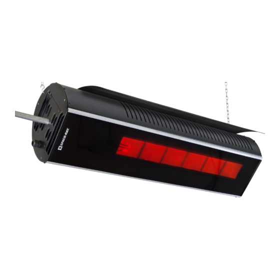
INSTALLATION AND OPERATION INSTRUCTIONS
INFRARED RADIANT PATIO HEATER
OWNER / INSTALLER: For your safety this manual must be carefully and thoroughly read and understood before
installing, operating or servicing this heater. This heater is intended for use with either Natural Gas or Propane
Gas. It must be installed by a qualified service person or a licensed contractor in accordance with state and local
codes.
: Improper installation, adjustment, alteration, service, or maintenance can cause property
damage, injury or death. Read the installation, operation and maintenance instructions thoroughly before
installing or servicing this heater. For assistance or additional information, consult a qualified installer, service
agency or the gas supplier.
For Indoor Installations INSPECT all combustion air openings into the building and, if necessary, clear if they
become blocked.
FOR YOUR SAFETY: If this heater is installed indoors, it must be in a sufficiently ventilated space. Exhaust fans
MUST be operating on an appropriate cycle when heaters are operating to avoid a high concentration of carbon
monoxide. When installed in insufficient ventilated spaces this heater may give off carbon monoxide, an
odorless and poisonous gas. CARBON MONOXIDE POISONING MAY LEAD TO DEATH. Early signs of carbon
monoxide poisoning resemble the flue with headaches, dizziness and nausea. If you experience these signs, GET
FRESH AIR IMMEDIATELY! Have the heaters serviced as soon as possible and check the ventilation into the
building.
INSTALLER: This manual is the property of the owner. Please present this manual to the owner when you leave
the job site.
IF YOU SMELL GAS:
1. Shut off gas to the appliance.
2. Extinguish any open flame.
3. If odor continues, keep away from the
appliance and immediately call your gas
supplier.
!IMPORTANT: SAVE THIS MANUAL FOR FUTURE REFERENCE.
Phone 01473 830551 Fax 01473 832055 www.spaceray.co.uk email:
Form 44201360
Oct 2019
COLD BLOCKER™
Models: WB10CE-N7 and L7
Two Stage (or Single stage)
UNVENTED - (For all Outdoor applications
and Indoor Non-Residential Spaces)
DANGER
Gas Fired Products (UK) Ltd.
Chapel Lane, Claydon, Ipswich, Suffolk IP6 0JL, England
DO NOT store or use petrol or other flammable
vapors and liquids in the vicinity of this or any
other appliance.
An LP-cylinder not connected for use shall not
be stored in the vicinity of this or any other
appliance.
info@spaceray.co.uk
Advertisement
Table of Contents

Summary of Contents for Space-Ray COLD BLOCKER WB10CE-N7
- Page 1 INSTALLATION AND OPERATION INSTRUCTIONS INFRARED RADIANT PATIO HEATER COLD BLOCKER™ Models: WB10CE-N7 and L7 Two Stage (or Single stage) UNVENTED - (For all Outdoor applications and Indoor Non-Residential Spaces) OWNER / INSTALLER: For your safety this manual must be carefully and thoroughly read and understood before installing, operating or servicing this heater.
-
Page 2: Table Of Contents
Table of Contents 1.0) SAFETY ................................... 7 2.0) INSTALLER RESPONSIBILITY ............................ 7 3.0) GENERAL INFORMATION ............................7 4.0) MINIMUM CLEARANCES TO COMBUSTIBLES ......................9 5.0) SPECIFICATIONS ..............................12 6.0) PACKING LIST ............................... 13 7.0) HEATER SIZING GUIDELINES ..........................13 8.0) TYPICAL HEATER LAYOUTS ........................... -
Page 3: Safety
1.0) SAFETY This heater is a self-contained infrared radiant ceramic heater. Safety information required during installation and operation of this heater is provided in this manual and the labels on the product. The installation, service and maintenance of this heater must be performed by a contractor qualified in the installation and service of gas fired heating equipment. - Page 4 SAFETY REQUIREMENTS The heater area must be kept clear and free from combustible materials, gasoline and other flammable vapors and liquids. This heater is designed for use with one type of gas (G20, G31, etc.). Make sure that the type of gas to be supplied to this heater matches that shown on the heater rating plate.
-
Page 5: Minimum Clearances To Combustibles
Consideration also must be given to service accessibility. Space-Ray will not recognize the warranty for any use other than space heating. This heater is for Indoor and Outdoor Installation and is used in Unvented mode. The term Unvented actually means Indirect Vented. - Page 6 “specify the maximum permissible stacking height to maintain the required clearances from the heater to combustibles.” Space-Ray recommends posting these signs adjacent to the heater thermostat or other suitable location that will provide enhanced visibility.
- Page 7 Clearance to combustibles dimensions are shown below. Form 44201360 Oct 2019...
-
Page 8: Specifications
2.4 to 3.4m 2.15 to 2.7m 2.15 to 2.44 WB10CE-L7 * For mounting heights outside the recommended distances consult your local Space-Ray Representative. Ignition System (direct spark): 1.5 second pre-purge period 10 second trial for ignition period 15 second inter-purge period... -
Page 9: Packing List
Minimums are shown as a guideline for human comfort. For more assistance with patio heater sizing and layout please contact your local Space-Ray representative. Form 44201360... -
Page 10: Typical Heater Layouts
8.0) TYPICAL HEATER LAYOUTS The diagram below shows the recommended spacing layout between heaters. Dimension Horizontal 15 to 30 degree angle Above 30 degree angle Min. Max. Min. Max. Min. Max. A. Mounting Height 2.4m 3.4m 2.15m 2.7m 2.15m 2.4m B. -
Page 11: Dimensions
9.0) DIMENSIONS 10.0) ACCESSORIES Below are the optional accessories available for the Wind Blocker Patio heater. Description Picture 44560350 Wall / Ceiling Telescopic Mounting Bracket Kit- 380-560mm overhead space (check clearances to combustibles space above the heater before ordering) 44560351 Ceiling Telescopic Mounting... -
Page 12: Unpacking The Heater
Description Picture 44560352 Wall / Ceiling Telescopic Mounting Bracket Kit- 15"-30" overhead space (check clearances to combustibles space above the heater before ordering) includes both the 380-560mm (15-22”) and 560-760mm (22-30”) extension legs. 44566300 Heat Shield – Reduced clearances to combustible option when installed. -
Page 13: Installation
It is recommended that two people lift the heater out of the carton. Do not remove from the remaining packaging until the heater is ready to be hung. 12.0) INSTALLATION In order to protect the ceramic glass it is recommended to only insert the ceramic glass once all the other installation steps have been completed. -
Page 14: Heater Mounting Angle
g) The heater must be suspended with its longitudinal axis horizontal, but may have its lateral axis at an angle from 0° to 60° from the horizontal, as shown in the minimum clearances to combustibles section 4.0). h) An optional heat shield may be installed to reduce the top distance of clearance to combustibles. This heat shield should be installed prior to hanging the heater. -
Page 15: Indoor Installation - Hanging Methods
12.2) INDOOR INSTALLATION – HANGING METHODS When the heater is used for an Indoor Installation then the following hanging methods may be used. The heater can be hung from the ceiling, secondary steel work, etc. using chains, threaded rods and other approved hanging materials. - Page 16 The hanging brackets are supplied as an optional accessory item. Below are the kit contents. 44560350 44560351 44560353 Item No. Part No. Description Quantity Quantity Quantity 02140040 HHCS,1/4-20 x 1/2" SS 02129100 WASHER, FLAT 1/4"N SS 02167019 LOCKNUT, 1/4-20 KEPS - SS 44560259 HANGER BRACKET –...
- Page 17 12.3.1) HANGING BRACKETS ASSEMBLY A left-hand LH and right-hand RH bracket must be assembled. Torque screws and locknuts to 6.8Nm. To mount the hanging brackets to the wall/ceiling: 1. Measure and mark distances for the hanger bracket holes. 2. Hanging brackets should first be fixed to the wall or ceiling surface by means of 4 lag bolts – not supplied (M10 x 75mm (3/8”...
-
Page 18: Heat Shield Installation
13.0) HEAT SHIELD INSTALLATION A heat shield can be used to reduce the clearance to combustible distances. Refer to Minimum Clearance to Combustibles in Section 4). The heat shield is available as an accessory Kit No. 44566300. Item No. Part No. Description Quantity 02359000... - Page 19 The heat shield position on the heater is dependent on the heater mounting angle. Use the angle gauge provided with the heater to determine the mounting angle before proceeding with the heat shield assembly. See Section 12.1 See below for installation steps. Step 1.
- Page 20 IMPORTANT: Use the Dome Cap nuts at the control end of the heater as shown in the illustrations so that the heat shield can expand when the heater is turned on. Failure to do so may result in the heat shield distorting.
-
Page 21: Installation Of The Ceramic Glass
14.0) INSTALLATION OF THE CERAMIC GLASS Only install the ceramic glass once the heater has been attached to a suitable gas (see Section 15.0), electrical supply (see Section 16.0) and has been commissioned (see Section 18.0). Read this section to the end to avoid glass breakage. 1. -
Page 22: Gas Connections And Regulation
15.0) GAS CONNECTIONS AND REGULATION Use an approved flexible gas connector of 600mm minimum length when installing the heater with flexible hanging methods as described in Section 12.0). IMPORTANT BEFORE CONNECTING THE GAS TO THE HEATER a) Connect to the supply tank or manifold in accordance with National or local building codes. Authorities having jurisdiction should be consulted before the installation is made. - Page 23 h) The gas pipe, flexible hose and connections must be self-supporting. The gas pipe work must not bear any of the weight of the heater or any other suspended assembly. This appliance is equipped with a fast-opening, combination gas valve. The maximum supply pressure to the appliance is 60 mbar.
-
Page 24: Instructions For Pressure Test Gauge Connection
15.1) INSTRUCTIONS FOR PRESSURE TEST GAUGE CONNECTION 15.2) INLET GAS PRESSURE CHECK 1. Turn off all electrical power and manual gas shutoff valve to the system to connect manometer hoses. 2. Turn the pressure test screw in the center of the gas valve test boss (see Figure 1 below) not more than one turn counterclockwise. -
Page 25: Electrical Connections
DO NOT EXCEED THE PRESSURES SHOWN IN THE GAS PRESSURE TABLE. After testing pressure and adjusting the regulator, turn off all electrical power to the system, remove manometer hoses, turn outlet test screw clockwise to seal pressure port. Tighten to 1.0 Nm torque minimum. Turn on system power. - Page 26 4. Using flexible international harmonized 3-wire PVC (thermoplastic jacket) supply cable with earth (0.50 mm National or Local standard specifications) connect the power supply leads to the terminal block and earth connection located inside the control housing as follows: Brown (red) - to terminal marked L Blue (Black) - to terminal marked N...
-
Page 27: Internal Connection Wiring Diagram
16.1) INTERNAL CONNECTION WIRING DIAGRAM The figure below shows the internal wiring diagram of the heater and the optional external connections depending on how the heater will be controlled. NOTE: In the event of an electrical fault after installation of the appliance, preliminary system checks are required to be carried out i.e. - Page 28 A. 3 POSITION SWITCH CONNECTIONS - SINGLE HEATERS B. 3 POSITION SWITCH CONNECTIONS - MULTIPLE HEATERS C. THERMOSTAT CONNECTIONS - SINGLE HEATERS D. THERMOSTAT CONNECTIONS - MULTIPLE HEATERS Form 44201360 Oct 2019...
-
Page 29: Field Connections And Wiring Diagrams - Single Stage
16.3) FIELD CONNECTIONS AND WIRING DIAGRAMS – SINGLE STAGE The figure below shows the internal connection to operate the heater turning on and off 230V power to the heater. Important: To operate the heater as single stage a jumper wire must be installed across the LO and HI terminals as shown below. -
Page 30: Ventilation
17.0) VENTILATION This heater is approved for both INDOOR and OUTDOOR installation. Both installation options have different ventilation requirements as described below. These must be observed. OUTDOOR space is defined as an amply ventilated area that must have a minimum of 25% of the surface area open. -
Page 31: Lighting And Shutdown Instructions
Ventilation by Mechanical Evacuation Ventilation by mechanical evacuation is sufficient if 10 m /h of exhaust air per kW of operating heat input are ventilated out of the installation room. The air/products of combustion mixture must be evacuated above the radiant heaters using fan(s). It shall only be possible to operate the radiant heaters whilst the exhaust airflow is proven. -
Page 32: Sequence Of Operation
Direct Burner Spark Ignition Modules. 1. Turn on the gas supply to the appliance. 2. Set any time switch or thermostats to demand heat. 3. Switch on the electrical supply to the appliance. 4. Following a 1.5 second pre-purge the burner should ignite within 10 seconds. 5. - Page 33 This heater must be cleaned and serviced annually by a qualified contractor before the start of each heating season and at any time excessive accumulation of dust and dirt is observed. Maximum heating efficiency and clean combustion will be maintained by keeping the heater clean. Detailed instructions for component removal are given in Section 21.0) Replacing Parts.
-
Page 34: Trouble Shooting
Main Burner and Orifice: Check the Main burner and orifice; remove any dirt or debris including spider webs. Foreign Objects: Check and remove any foreign objects that are logged between the heat shield and the heater. Ceramic Glass: Clean the glass from the inside and outside using a damp cloth. See also Section 21.1) for safe removal of glass. - Page 35 Form 44201360 Oct 2019...
-
Page 36: Replacing Parts
21.0) REPLACING PARTS 21.1) REMOVAL OF GLASS PANEL 1. Remove the glass retainer 1. 2. Carefully slide the glass panel 2 from the retainer rails and away from heater. Access to the gas control valve and ignition module can now be made by loosening the screws from the access panel assembly. -
Page 37: Removal Of Spark Electrode/Flame Sensor
21.2) REMOVAL OF SPARK ELECTRODE/FLAME SENSOR 1. Remove the glass panel as shown in Section 21.1). Open the access panel assembly by loosening the screws. 2. Disconnect the ignition cable and flame sensor wires (not shown) from the spark electrode/flame sensor. 3. -
Page 38: Removal Of Gas Valve/Ignition Control Module
21.4) REMOVAL OF GAS VALVE/IGNITION CONTROL MODULE 1. Open the access panel assembly as shown in Section 21.2). Note: This is removed from the illustration for clarity. Loosen the panel nut 1 using a 19mm (¾”) end wrench and remove from the gas valve manifold. 2. -
Page 39: Disassembly Of Gas Valve/Ignition Control Module
21.5) DISASSEMBLY OF GAS VALVE/IGNITION CONTROL MODULE 1. Open the access panel assembly as shown in Section 21.2) Note: This is removed from the illustration for clarity. 2. Remove the gas valve/ignition control module assembly as shown in 21.4). 3. Remove 12 way Molex connector (not shown) from ignition module. 4. -
Page 40: Conversion Instructions
3. Slide the burner slightly toward the front of the heater. 4. Rotate the burner away from the heater. 5. Slide the burner out from the heater. Replace the burner in reverse order. 22.0) CONVERSION INSTRUCTIONS a) Remove the Injector from the Injector Fitting (see Section 21.3) and replace it with the alternative Injector supplied with conversion kit. -
Page 41: Replacement Parts Guide
24.0) REPLACEMENT PARTS GUIDE Item No. Part No. Description Qty. Main Heater Components 02352000 Screw, Pan Head Thread #8 x 1/2" Type AB SS Black Oxide 02261030 Ground Screw #8-32 x 3/8" (Green Coated - Type F) 02132089 Rivet 1/8" x .337" SS (grip range .126 – .187) – not shown - 02168050 Screw, Pan Head Machine #10-24 x 3/8”... - Page 42 42604608 Label, Indoor/Outdoor Installation 42604607 Label, Outdoor Installation 44201360 Manual, Installation and Operation Instructions IMPORTANT: Please order by Part Number, not by Item Number. Refer to complete Model Number when ordering. All replacement parts prices are available when ordering. MODEL NUMBER SUFFIXES: N7 = Natural Gas L7 = Propane Gas...
- Page 43 Form 44201360 Oct 2019...
Need help?
Do you have a question about the COLD BLOCKER WB10CE-N7 and is the answer not in the manual?
Questions and answers