Table of Contents
Advertisement
Quick Links
Advertisement
Table of Contents

Related Manuals for TECSYSTEM VRT200


Summary of Contents for TECSYSTEM VRT200
- Page 1 INSTRUCTION MANUAL VRT200 1MN0046 REV. 2 operates with ISO9001 certified quality system TECSYSTEM S.r.l. 20094 Corsico (MI) Tel.: +39-024581861 Fax: +39-0248600783 http://www.tecsystem.it R. 1.7 01/08/19 ENGLISH “Translations of the original instructions”...
-
Page 2: Table Of Contents
INTRODUCTION First of all we wish to thank you for choosing to use a TECSYSTEM product and recommend you read this instruction manual carefully: You will understand the use of the equipment and therefore be able to take advantage of all its functions. -
Page 3: Safety Requirements
Failure to comply with these instructions can cause damages, fires or electric shock, and possible serious injuries! POWER SUPPLY The VRT200 ED17 can be supplied by 85/250Vca 50/60Hz. Before using it, make sure the power cable is not damaged, kinked or pinched. Do not tamper with the power cable. Never disconnect the unit by pulling the cable, avoid touching the pins. -
Page 4: Accessories
1 motor line terminal 4 poles pitch 5 Code: 2PL0369 - Screws tightening torque 0.5Nm 1MN0030 REV. 2 ATTENTION: always install the device using the terminals included in the pack. The use of terminals other than those included with the control unit might cause malfunctions. VRT200... -
Page 5: Technical Specifications
VRT200 TECHNICAL SPECIFICATIONS POWER SUPPLY Supply rated values 85-250 Vca (10 A max) 50/60 Hz INPUTS ● 2 inputs enabling remote control ENABLE: COM-EN1-EN2 ● Connections on removable terminal strips OUTPUTS ● 1 fault sensor or operating failure (FAULT) relay SPDT Ф... - Page 6 VRT200 TECHNICAL SPECIFICATIONS TEST AND PERFORMANCE ● Ambient operating temperature from –20°C to +60°C ● Humidity 90% non-condensing ● Housing NORYL 94 _V0 ● Absorption 5VA (max) Protection treatment of the electronic part Option ● Frontal film polycarbonate IP65 DISPLAY AND DATA MANAGEMENT ●...
-
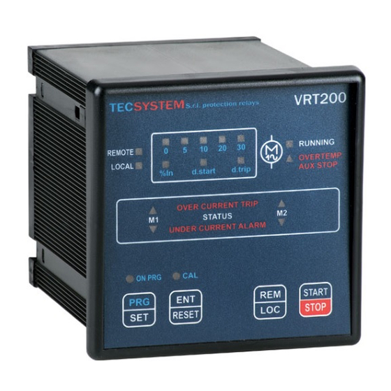
Page 7: Front Panel
Fans' control mode REM/LOC button Programming selection LED (yellow) (REMOTE or LOCAL) (% In, d.start, d.trip) ENT/RESET button: alarm reset and Monitoring delay LED (yellow) at start up programming data selection d.start 10) Motors' auto-tuning phase LED (yellow) Trip delay LED (yellow) d.trip VRT200... -
Page 8: Installation
Drill a 92 x 92 mm hole in the panel sheet. 1MN0063 REV. 0 Panel hole dimensions (+0.8mm tolerance) Control unit Identification label Fix the unit securely with the blocks supplied. 1MN0008 REV. 0 Control unit Fixing screw Fixing block Crosshead screwdriver #1X100mm VRT200... -
Page 9: Electrical Connections
7 8 9 7 8 9 FAULT 8-9 NC: ALARM FAULT OR POWER OFF FAULT 7-9: NC POWER ON EXAMPLE OF CONNECTION VRT200 ED17 EXAMPLE OF CONNECTION VRT200 ED17 TEMPERATURE CONTROL UNIT WITH FAN1 TEMPERATURE CONTROL UNIT WITH FAN1 AND... -
Page 10: Power Supply
POWER SUPPLY The VRT200 control unit must be supplied with 85- 250Vca50/60Hz, terminals 40-42, terminal 41 ground (check the connection diagrams on pages 9). A variation in the network voltage of over 10% might cause alarms because of the current variation in the load. - Page 11 ATTENTION: We recommend you check the control unit before starting the device. The default parameters set by TECSYSTEM might not suit your requirements. Programming the device is the end user’s responsibility: the set alarm thresholds and the enabled functions described in this manual must be checked (by a specialized technician) referring them to the application and system characteristics on which the control unit is installed.
-
Page 12: Intellifan Function
Before you enable the function, always check that the connection between the two FAN 1 and FAN 2 contacts, of the monitoring unit, and the VRT200 is: FAN1 contact with COM - EN1, FAN 2 contact with COM - EN2, example at page 9. -
Page 13: Equipment Disposal
Returning used electrical devices: contact TECSYSTEM or the TECSYSTEM agent for information on the correct disposal of the devices TECSYSTEM is aware of the impact its products have on the environment and asks its customers active support in the correct and environmentally-friendly disposal of its devices...
Need help?
Do you have a question about the VRT200 and is the answer not in the manual?
Questions and answers