Table of Contents
Advertisement
Quick Links
Advertisement
Table of Contents

Related Manuals for TECSYSTEM NT538 WS EVO


Summary of Contents for TECSYSTEM NT538 WS EVO
- Page 1 INSTRUCTION MANUAL NT538 WS EVO 2MN0200 REV. 0 operates with ISO9001 certified quality system TECSYSTEM S.r.l. 20094 Corsico (MI) Tel.: +39-024581861 Fax: +39-0248600783 http://www.tecsystem.it R. 1.1 16/11/2020 ENGLISH “Translations of the original instructions”...
-
Page 2: Table Of Contents
INTRODUCTION First of all we wish to thank you for choosing to use a TECSYSTEM product and recommend you read this instruction manual carefully: You will understand the use of the equipment and therefore be able to take advantage of all its functions. - Page 3 ………………………………….. 8) FAILSAFE FUNCTION — ………………………………….. 9) Pt100 EXTENSION CABLE TECHNICAL SPECIFICATIONS ………………………………….. 10) FCD FUNCTION — ………………………………….. 11) NT538 WS EVO WI-FI CONNECTION ………………………………….. 12) TECSYSTEM WEB SERVER ………………………………….. • HOME SCREEN — • ………………………………….. TEMPERATURE AND ALARMS SCREEN …………………………………..
-
Page 4: Safety Requirements
POWER SUPPLY The NT538 WS EVO control unit has universal power supply, i.e. it can be supplied by 85 to 260 Vac-Vdc, irrespectively of polarity in Vdc. Before using it, make sure the power cable is not damaged, knotted or pinched. Do not tamper with the power cable. -
Page 5: Accessories
Code: 2PL0430 - Screw tightening torque 0.25Nm 1 external Wi-Fi SMA Antenna ATTENTION: always install the device using the terminals included in the pack. The use of terminals other than those included with the control unit could cause malfunctions. NT538 WS EVO... -
Page 6: Technical Specifications
TECHNICAL SPECIFICATIONS NT538 WS EVO POWER SUPPLY 85-260 Vac-Vdc Supply rated values 50/60HZ ● Vdc with invertible polarities INPUTS ● 8 inputs for three-wire Pt100 RTD sensors (max section 1.5mm²) ● Connections on removable terminal boards ● Input channels protected against electromagnetic interference Thermo resistances cable compensations 500m (1 mm²) - Page 7 TECHNICAL SPECIFICATIONS NT538 WS EVO ● Digital linearity of sensor signal ● Self-diagnostic circuit Optional Electronic part protective treatment 3V 220mAh Internal battery for RTC power supply DISPLAY AND DATA MANAGEMENT ● 2 x 13 mm displays with 3 digits to display temperatures, messages and channels ●...
-
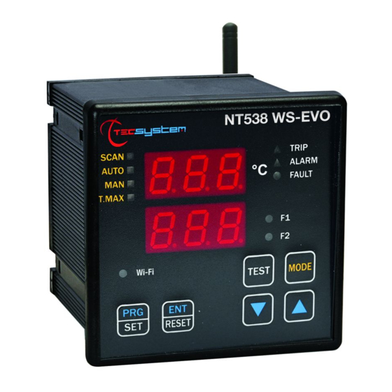
Page 8: Front Panel
FAN 1 (yellow) LED T-max mode selection (red) LED FAN 2 (yellow) LED Man mode selection (yellow) LED Display mode selection key Auto mode selection (green) LED Fixing blocks Scan mode selection (yellow) LED UP key Fixing blocks DOWN key NT538 WS EVO... -
Page 9: Display
We suggest carrying out the control unit LED test regularly. For this operation, press the TEST key briefly; all the displays turn on for 2 seconds. If one of the LEDS does not work, please return the control unit to TECSYSTEM for repair. ALARM RELAY TEST This function allows you to carry out a test of the relay operation without having to use further devices. -
Page 10: Assembly
Drill a hole in the panel sheet with dimensions of 92 x 92 mm. 1MN0007 REV. 0 Control unit Panel hole dimensions (+0.8 mm tolerance) Identification label Secure the appliance firmly by means of the supplied fixing blocks. 1MN0008 REV. 0 Control unit Fixing screws Fixing blocks Cross-head screwdriver #1X100mm NT538 WS EVO... -
Page 11: Electrical Connections
ELECTRICAL CONNECTIONS The Wi-Fi antenna (5) is supplied with the NT538 WS EVO NT538 WS EVO device. If necessary, the antenna connection can be extended using a 5 mm SMA Male to Female antenna cable. NOTE: Never start device with antenna disconnected. -
Page 12: Power Supply
POWER SUPPLY The NT538 WS EVO can be supplied by 85 to 260 Vac-Vdc, 50/60 Hz irrespectively of polarity in Vdc (terminals 40-42). This is obtained thanks to the use of a tested power supply unit, newly designed and manufactured, that frees installers from worrying about the correct Vac and Vdc supply. -
Page 13: Programming
PROGRAMMING NT538 WS EVO PITCH PRESS EFFECT PRESS NOTES Press and hold the PRG button until the display shows Select PRG SET to proceed with programming or PRG 1 PRG 1 default data to load the default values with YES the CH1 is... -
Page 14: Programming Notes
We recommend you check the device's programming before starting the device. The default parameters set by TECSYSTEM might not match your requirements. Programming the device is the end user's responsibility. The settings of the alarm thresholds and enabling of the functions described in this manual must be checked (by a specialist engineer) according to the application and features of the system the control unit is installed on. -
Page 15: Temperature Sensors
Pt100 sensors c) damage to the Pt100 inputs of the control unit. TECSYSTEM S.r.l. has designed its own special cable to transfer the measurement signals, CEI-compliant, with all the protection requirements provided for mod. CT-ES NOTE: the use of cables not complying with the above could cause possible reading anomalies. -
Page 16: Temperature Sensor Diagnostics
CAL message display: the indication appears when the measurement circuit is damaged. The temperature values displayed might be incorrect. Return the control unit to TECSYSTEM for repairs. VOTING FUNCTION The voting function derives from the redundancy concept that consists in duplicating the components of a system to increase their reliability. -
Page 17: Programmed Data Diagnostics
ON and OFF to cool the controlled system. The high flexibility of the NT538 WS EVO is used to choose, for each channel, an operating mode to manage the contacts of FAN1 and FAN2. While programming the individual enabled channel, there will be a prompt to select one of the following FAN activation modes, dedicated to that channel: •... -
Page 18: Failsafe Function
FAIL SAFE FUNCTION The NT538 WS EVO control unit has the selection n.o (normally open contact)/n.c (normally closed contact) for the ALARM, TRIP and FAULT relays, programming steps from 26 to 31 page 14. Selecting the YES/NO setting introduces the Fail Safe and No Fail Safe functions. -
Page 19: Fcd Function
NOTE: it is advisable not to enable the FCD function with VOTING active. NT538 WS EVO WI-FI CONNECTION The NT538 WS EVO control unit has a built-in WEB SERVER that is accessible via Wi-Fi connection. What is needed to access the NT538 WS EVO control unit? To access the web server a device with a Wi-Fi connection and an Internet browser is needed. - Page 20 TECSYSTEM (S/N + YEAR) NOTE: the name of the network to connect to consists of: TECSYSTEM followed by the serial number S/N of the device and the year of production (20 = 2020), valuesshown on the identification label of the product purchased.
-
Page 21: Tecsystem Web Server
TECSYSTEM WEB SERVER Through the Wi-Fi connection, the TECSYSTEM WEB SERVER interface allows the user to access all the information present on the web server integrated in the NT538 WS EVO. To take full advantage of the product features it is advisable to connect the NT538 WS to a Wi-Fi network (STATION mode). -
Page 22: Home Screen
ALR signal ON red LED (ALARM) FOC signal ON red LED TRP signal ON red LED (TRIP) (*) the label indication can be customised by the user in the options – labels settings screen, see page 25. NT538 WS EVO... -
Page 23: Settings Screen
After entering the PIN CODE, default 00000, by pressing the SAVE SETTINGS key the user updates the programming data of the NT538 WS EVO device. The control unit will lose the connection for a few seconds, the device will reset after which the new values will be available on the updated screen. -
Page 24: Network Settings
We recommend you check the device's programming before starting the device. The default parameters set by TECSYSTEM might not match your requirements. Programming the device is the end user's responsibility. The settings of the alarm thresholds and enabling of the functions described in this manual must be checked (by a specialist engineer) according to the application and features of the system the control unit is installed on. -
Page 25: Options
After entering the PIN CODE, default 00000, press SAVE to save the set values. A POP UP window will confirm correct saving of the data. Note: PIN CODE settings and operation on page 29. Press BACK to return to the previous screen NT538 WS EVO... -
Page 26: E-Mail Settings
After entering the PIN CODE, default 00000, press SAVE to save the set values. A POP UP window will confirm correct saving of the data. Press BACK to return to the previous screen Note: PIN CODE settings and operation on page 29. NT538 WS EVO... -
Page 27: Trend Chart Screen
By pressing the EXPORT key it is possible to download all the recorded temperature values in CSV format (text file). Before pressing the export button, select the year you want to export. CSV file export notes on page 29. NT538 WS EVO... -
Page 28: Event Log Screen
TRIP ON activation signal on CHn channel identified Modbus error Modbus error signal Internal error Signal internal web server error Log index recovered Signalling of events log indices reset Log index cleared Report deletion of events log indices NT538 WS EVO... -
Page 29: Trend Chart Notes
Type the new desired pin code in the appropriate box, maximum 5 numbers (SHOW to display the PIN CODE). Press SAVE to save the pin A POP UP window will confirm the correct saving. PIN CODE default setting: 00000 Press BACK to main page to return to the main screen NT538 WS EVO... -
Page 30: Statistics Screen
It can be used to automatically receive an update on the operation of the monitored electric machine, without wasting any time. By analysing the periodic reports received, directly on their own e-mail, the maintenance technicians will be able to identify any anomalies and plan in advance the interventions on the systems NT538 WS EVO... -
Page 31: Troubleshooting
"Tecsystem s.r.l. General Sales Conditions", which can be consulted on the website www.tecsystem.it and/or in the stipulated purchase contract. The warranty is considered valid only when the product is damaged by causes attributable to TECSYSTEM srl, such as manufacturing or components defects. -
Page 32: Equipment Disposal
Returning of used electrical appliances: contact TECSYSTEM or the TECSYSTEM agent to receive information on correct disposal of the appliances. TECSYSTEM is aware of the impact its products have on the environment and asks its customers active support in the correct and environmentally-friendly disposal of its devices.
Need help?
Do you have a question about the NT538 WS EVO and is the answer not in the manual?
Questions and answers