TECSYSTEM T119 DIN Instruction Manual
Hide thumbs
Also See for T119 DIN:
- Instruction manual (14 pages) ,
- Setup and programming (24 pages) ,
- Instruction manual (13 pages)

Related Manuals for TECSYSTEM T119 DIN


Summary of Contents for TECSYSTEM T119 DIN
- Page 1 INSTRUCTION MANUAL T119 DIN 1MN0109 REV. 0 operates with ISO9001 certified quality system R. 1.1 25/08/16 ENGLISH “Translations of the original instructions”...
-
Page 2: Table Of Contents
INTRODUCTION First of all we wish to thank you for choosing to use a TECSYSTEM product and recommend you read this instruction manual carefully: You will understand the use of the equipment and therefore be able to take advantage of all its functions. -
Page 3: Safety Requirements
POWER SUPPLY The T119 DIN control unit has UNIVERSAL power supply, i.e. it can be supplied by 24 to 240 Vac-Vdc, irrespectively of polarity in Vdc. Before using it, make sure the power cable is not damaged, knotted or pinched. Do not tamper with the power cable. -
Page 4: Accessories
ACCESSORIES The following objects are present inside the box: Control unit 1 supply terminal 3 poles pitch 5 Code: 2PL0367 1 PTC sensor terminal 4 poles pitch 5 Code: 2PL0369 1 relay terminal 8 poles pitch 5 Code: 2PL0374 1MN0030 REV. 0 ATTENTION: always install the device using the terminals included in the pack. -
Page 5: Technical Specifications
T119DIN TECHNICAL SPECIFICATIONS POWER SUPPLY 24 -240Vac-dc Supply rated values 50/60HZ Maximum ratings 20-270 Vac-dc ● Vdc with reversible polarities ● INPUTS 3 series of PTC inputs ● 1 series for L1 (ALARM) ● 1 series for L2 (TRIP) ● 1 series for FAN ●... -
Page 6: Introduction
● INTRODUCTION The T119 DIN is the most advanced unit on the market as regards temperature monitoring units for MV cast resin transformers which utilize PTC sensors. The unit gives the L1 pre-alarm and L2 alarm-trip signals when the temperature limits sensed by the PTCs in the coils are reached. -
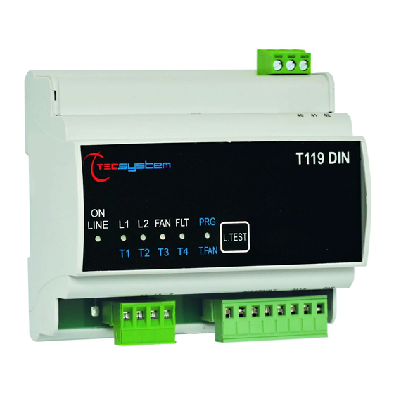
Page 7: Front
FAULT LED - L1 LED - L2 LED - FAN LED flashing, see PTC SENSOR FAULT DIAGNOSIS on page 10. POWER SUPPLY The T119 DIN control unit has UNIVERSAL power supply, i.e. it can be supplied by 24 to 240 Vac-Vdc, 50/60 Hz irrespectively of polarity in Vdc (terminals 40-42). -
Page 8: Programming
PROGRAMMING FAN PROGRAMMING CYCLE STEP ACTION EFFECT Turn on the unit the green LED lights up Push TEST twice in sequence the red PRG LED flashes Push TEST within 5" without releasing it until the the PRG LED is ON continuously PRG LED is ON the red LED switches from Push TEST within 5"... -
Page 9: Led Test
If the FAN is set up, the relay activates when the relative PTC sends the first signal and the FAN LED is steady ON: the relay is active for as long as the PTC senses the temperature is normal, the T119 DIN unit keeps the relay ON for the time set during programming and the FAN LED flashes. -
Page 10: Sensor Diagnostic Device
PTC FAN The FAULT +FAN LEDs are flashing ATTENTION If the T119 DIN control unit is not connected to the correct PTC model, the LEDS flash. The PTC temperature is nat + T = 1300 ohm. "PTC" TYPE TEMPERATURE SENSORS The PTCs can be compared to bimetallic thermostats where the contact opens and closes at the approximate temperature, defined as their operating characteristic (NAT=operating temperature). -
Page 11: Ptc Technical Specifications
The resistance value shown in table 1 refers to a single or multiple series of PTCs. The correct operation of the device is obtained by complying with the stated resistance values. In case the single or multiple series of PTCs have resistance values other than the stated, please contact TECSYSTEM Srl - Technical Service. -
Page 12: Sensor / Relay Electrical Connections
SENSOR / RELAY ELECTRICAL CONNECTIONS 1MN0109 REV. 0 Universal unit supply 24-240 Vac-dc 50/60Hz. Relays (ALARM/FAULT-ALL2-FAN) L1 - L2 - FAN PTC sensor lines RELAYS PTC SENSORS L1 L2 FAN COM STOP SYSTEM ALARM / FAULT AUDIO AND VISUAL INDICATION 1MN0095 REV. -
Page 13: Warranty Conditions
Returning used electrical devices: contact TECSYSTEM or your TECSYSTEM agent for information on the correct disposal of the devices. TECSYSTEM is aware of the impact its products have on the environment and asks its customers active support in the correct and environmentally-friendly disposal of its devices.
Need help?
Do you have a question about the T119 DIN and is the answer not in the manual?
Questions and answers