Table of Contents
Advertisement
Quick Links
Advertisement
Table of Contents

Related Manuals for TECSYSTEM T154WS


Summary of Contents for TECSYSTEM T154WS
- Page 1 INSTRUCTION MANUAL T154 WS 1MN0202 REV. 0 operates with ISO9001 certified quality system TECSYSTEM S.r.l. 20094 Corsico (MI) Tel.: +39-024581861 Fax: +39-0248600783 http://www.tecsystem.it R. 1.0 04/11/2020 ENGLISH “Translations of the original instructions”...
-
Page 2: Table Of Contents
INTRODUCTION First of all we wish to thank you for choosing to use a TECSYSTEM product and we strongly suggest that you read this instruction manual carefully: You will understand the use of the equipment and therefore be able to take advantage of all its functions. - Page 3 8) FAILSAFE FUNCTION — ………………………………….. 9) Pt100 EXTENSION CABLE TECHNICAL SPECIFICATIONS ………………………………….. 10) FCD FUNCTION — ………………………………….. 11) T154 WS WI-FI CONNECTION ………………………………….. 12) TECSYSTEM WEB SERVER • ………………………………….. HOME SCREEN — ………………………………….. • TEMPERATURE AND ALARMS SCREEN • …………………………………..
-
Page 4: Safety Requirements
To control the transformer correctly from a temperature point of view, enabling the VOTING function is allowed where the load distributed between the phases of the transformer is adequately balanced. TECHNICAL INFORMATION OR REPORTING INFORMATION Mail: ufficiotecnico@tecsystem.it - tel: 02/4581861 T154 WS... -
Page 5: Accessories
ACCESSORIES The following objects are present inside the box: Control unit Start guide and QR code 2 blocks for panel fixing 1 Terminal 3 pitch poles 5 supply Code: 2PL0367 - Screws tightening torque 0.5Nm 1 relay terminal 10 poles pitch 5 Code: 2PL0394 - Screws tightening torque 0.5Nm 1 Terminal 12 poles pitch 3.81 sensors Pt100 Code: 2PL0420 - Screw tightening torque 0.25Nm... -
Page 6: Technical Specifications
TECHNICAL SPECIFICATIONS T154 WS POWER SUPPLY 85-260 Vac-Vdc Supply rated values 50/60HZ ● Vdc with invertible polarities INPUTS ● 4 inputs for three-wire Pt100 RTD sensors (max section 1.5mm²) ● Connections on removable terminal boards ● Input channels protected against electromagnetic interference 500m (1mm²) Thermoresistances cable compensations OUTPUTS... - Page 7 TECHNICAL SPECIFICATIONS T154 WS ● Digital linearity of sensor signal ● Self-diagnostic circuit Protection treatment of the electronic part Optional 3V 220mAh Internal battery for RTC power supply DISPLAY AND DATA MANAGEMENT ● 2 x 13 mm displays with 3 digits to display temperatures, messages and channels ●...
-
Page 8: Front Panel
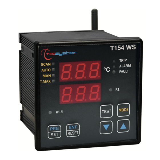
FRONT PANEL 1MN0202 REV.0 3-digit temperature display Enter/Reset button Control unit series Programming/Setting key TRIP (red) LED Led/relay test key ALARM (yellow) LED WI-FI (green) LED FAULT (red) LED 3-digit channel display FAN 1 (yellow) LED T-max mode selection (red) LED Display mode selection key Man mode selection (yellow) LED Fixing blocks... -
Page 9: Display
We suggest carrying out the control unit LED test regularly. For this operation, press the TEST key briefly; all the displays turn on for 2 seconds. If one of the LEDS does not work, please return the control unit to TECSYSTEM for repair. ALARM RELAY TEST This function allows you to carry out a test of the relay operation without having to use further devices. -
Page 10: Assembly
ASSEMBLY Drill a hole in the panel sheet with dimensions of 92 x 92 mm. 1MN0007 REV. 0 Control unit Panel hole dimensions (+0.8 mm tolerance) Identification label Secure the appliance firmly by means of the supplied fixing blocks. Connect the Wi-Fi antenna only after suitably fixing the device. 1MN0008 REV. -
Page 11: Electrical Connections
ELECTRICAL CONNECTIONS The Wi-Fi antenna (5) is supplied with the T154 WS device. If T154 WS necessary, the antenna connection can be extended using a 5 mm SMA Male to Female antenna cable. NOTE: Never start device with antenna disconnected. 1MN0202 REV.0 Pt100 sensors (white-red-red) 4) Access point key... -
Page 12: Power Supply
To protect the control unit against line overvoltages, the PT-73-220 electronic arrester, designed by TECSYSTEM S.r.l. for this specific purpose, is recommended. Alternatively, it is advisable to use 110 V AC supply voltages or, even better, 110 VDC. -
Page 13: Programming
PROGRAMMING T154 WS PITCH PRESS EFFECT PRESS NOTES Press and hold the PRG button until the display shows SET PRG Select PRG SET to proceed with programming or PRG 1 PRG 1 default data to load the default values The ALARM threshold for (CH 1-2-3) is displayed. Default 90°C Set the desired threshold, the Alarm LED flashes The TRIP threshold for (CH 1-2-3) appears and the Trip... -
Page 14: Programming Notes
HFN (NO) is displayed Fan cyclic test for 5 min. every “n” hours The FAN1 led flashes Default NO = function Set the desired number of hours disabled Fault for quick temperature FCD (NO) is displayed of the temperature (°C/sec) Set the desired value Default NO (FCD info on page 19) -
Page 15: Temperature Sensors
Pt100 sensors c) damage to the Pt100 inputs of the control unit. TECSYSTEM S.r.l. has designed its own special cable to transfer the measurement signals, CEI-compliant, with all the protection requirements provided for mod. CT-ES NOTE: the use of cables not complying with the above could cause possible reading anomalies. -
Page 16: Temperature Sensor Diagnostics
Activation of the functions: VOTING (shown below) or FCD (on page 19) in relation to the system conditions. CAL message display: the indication appears when the measurement circuit is damaged. The temperature values displayed might be incorrect. Return the control unit to TECSYSTEM for repairs. VOTING FUNCTION The voting function derives from the redundancy concept that consists in duplicating the components of a system to increase their reliability. -
Page 17: Temperature Diagnostics
TEMPERATURE DIAGNOSTICS When one of the thermometers detects a temperature higher than 1 ° C with respect to the pre-set value as the alarm limit, after approximately 5 seconds the ALARM relay switches and the channel ALARM LED (CHn)switches on. When the trip temperature limit is exceeded, after approximately 5 seconds the TRIP relay switches and the channel TRIP LED (CHn) switches on. -
Page 18: Failsafe Function
FAILSAFE FUNCTION The T154 WS control unit has the selection n.o (normally open contact) / n.c (normally closed contact) for the ALARM, TRIP and FAULT relays, programming steps from 26 to 31 page 14. Selecting the YES/NO setting introduces the Fail Safe and No Fail Safe functions. -
Page 19: Fcd Function
FCD FUNCTION The T series equipment boasts an innovative control function combined with the dynamic status of the Pt100 sensor. Activating FCD, the control unit analyses the increase in temperature ∆T (*) recorded in a second (°C/sec). Enabling the function, the user can select the value (ΔT) from a minimum of 1°C/sec up to a maximum of 30°C/sec. If the measured value is higher than the value set by the user, the control unit inhibits any activation of the ALARM and TRIP alarms and activates the switching of the FAULT relay (11-12), signalling on the display "fault for Fcd". - Page 20 TECSYSTEM (S/N + YEAR) NOTE: the name of the network to connect to consists of: TECSYSTEM followed by the serial number S/N of the device and the year of production (20 = 2020), valuesshown on the identification label of the product purchased.
-
Page 21: Tecsystem Web Server
TECSYSTEM WEB SERVER Through the Wi-Fi connection, the TECSYSTEM WEB SERVER interface allows the user to access all the information present on the web server integrated in the T154 WS. To take full advantage of the product features it is advisable to connect the T154 WS to a Wi-Fi network (STATION mode). -
Page 22: Home Screen
HOME SCREEN The home screen allows the user to identify the cabin and to select the various screens. The following information is shown in the management screen: Control unit model GRAPHICS screen selection key Station Name or monitored cabin (*) EVENT LOG screen selection key STATISTICS screen selection key Reference date... -
Page 23: Settings Screen
SETTINGS SCREEN In the settings screen it is possible to modify the programming of the T154 WS control unit. Key: BACK Return to the HOME screen Enabling of FAILSAFE FUNCTION Channel reference and enabling Relay: ALARM-TRIP-FAULT CH1-CH2-CH3 and CH4 Enabling FAN 1 channel FAN 1 limit programming boxes CH1-CH2-CH3 On and Off (from 1°C to 240°C) -
Page 24: Network Settings
We recommend you check the device's programming before starting the device. The default parameters set by TECSYSTEM might not match your requirements. Programming the device is the end user's responsibility, the settings of the alarm thresholds and the enabling of the functions described in this manual must be checked (by a specialist engineer) according to the application and features of the system the control unit is installed on. -
Page 25: Options
OPTIONS button Pressing the OPTIONS button accesses the options screen. On this page it is possible to: set the date and time in the Access Point mode, select the sampling interval, customise the labels (labels) station and channels and set the username and password useful to access the web server. -
Page 26: Graphics Screen
GRAPHICS SCREEN The Graphics screen allows the user to view the temperature trend of the CH1-CH2-CH3-CH4 enabled channels. it is also possible to export the values recorded on the CSV file. Key: BACK Return to the HOME screen Recording points display flag Time range CHn channel enabling flag Export key... -
Page 27: Events Screen
EVENT LOG SCREEN The Event log screen is used to quickly obtain an immediate overview of the events recorded by the control unit. Each event is identified with ID code, see event ID table. Key: BACK Return to the HOME screen Key: ORDER It is used to organise the... -
Page 28: Graph Display Notes
GRAPH DISPLAY NOTES When opening the graphs page, the last seven days recorded are displayed by default; if seven days are not available in memory, all the available data are displayed. The time range allows the user to set the graphic display period. The selections available are: last 24 hours, last 7 days and last 30 days. -
Page 29: Troubleshooting
"Tecsystem s.r.l. General Sales Conditions", which can be consulted on the website www.tecsystem.it and/or in the stipulated purchase contract. The warranty is considered valid only when the product is damaged by causes attributable to TECSYSTEM srl, such as manufacturing or components defects. -
Page 30: Equipment Disposal
Returning of used electrical appliances: contact TECSYSTEM or the TECSYSTEM agent to receive information on correct disposal of the appliances. TECSYSTEM is aware of the impact its products have on the environment and asks its customers active support in the correct and environmentally-friendly disposal of its devices.
Need help?
Do you have a question about the T154WS and is the answer not in the manual?
Questions and answers