Table of Contents
Advertisement
Quick Links
Advertisement
Table of Contents

Subscribe to Our Youtube Channel
Related Manuals for TECSYSTEM NT935BH-D


Summary of Contents for TECSYSTEM NT935BH-D
- Page 1 INSTRUCTION MANUAL NT935BH 1MN0189 REV. 0 operates with ISO9001 certified quality system TECSYSTEM S.r.l. 20094 Corsico (MI) Tel.: +39-024581861 Fax: +39-0248600783 http://www.tecsystem.it R. 1.0 10/06/20 ENGLISH “Translations of the original instructions”...
-
Page 2: Table Of Contents
INTRODUCTION First of all we wish to thank you for choosing to use a TECSYSTEM product and we strongly suggest that you read this instruction manual carefully: You will understand the use of the equipment and therefore be able to take advantage of all its functions. - Page 3 PAGE ………………………………….. 8) RS485 MODBUS • INTRODUCTION TO THE MODBUS INSIDE — ………………………………….. MODULE — ………………………………….. • OPERATING NOTES — • ………………………………….. DATA TRANSMISSION ON MODBUS NETWORK — ………………………………….. • RS485 ELECTRICAL CONNECTIONS ………………………………….. • DATA FRAME — ………………………………….. • DATA PACKET —...
-
Page 4: Safety Requirements
FUNCTIONS To control the transformer correctly from a temperature point of view, enabling the VOTING function is allowed where the load distributed between the phases of the transformer is adequately balanced. TECHNICAL INFORMATION Mail: ufficiotecnico@tecsystem.it tel: 02/4581861 NT935BH... -
Page 5: Accessories
ACCESSORIES The following objects are present inside the box: Control unit Start guide and QR code 2 blocks for panel fixing 1 Terminal 3 pitch poles 5 supply Code: 2PL0367 - Screws tightening torque 0.5Nm 1 relay terminal 12 poles pitch 5 Code: 2PL0361 - Screw tightening torque 0.5Nm 1 Terminal 12 poles pitch 3.81 sensors Pt100 Code: 2PL0420 - Screw tightening torque 0.25Nm... -
Page 6: Technical Specifications
NT935BH-D TECHNICAL SPECIFICATIONS POWER SUPPLY 85-260 Vac-Vdc Supply rated values 50/60HZ ● Vdc with invertible polarities INPUTS ● 4 inputs for three-wire Pt100 RTD sensors (max section 1.5mm²) ● Connections on removable terminal boards ● Input channels protected against electromagnetic interference Thermoresistances cable compensations 500 m (1 mm²) - Page 7 NT935BH-D TECHNICAL SPECIFICATIONS ● Digital linearity of sensor signal ● Self-diagnostic circuit Protection treatment of the electronic part Optional DISPLAY AND DATA MANAGEMENT ● 2 x 13 mm displays with 3 digits to display temperatures, messages and channels ● 3 LEDs to display the state of the alarms of the selected channel (ALARM-TRIP-FAULT) ●...
-
Page 8: Front Panel
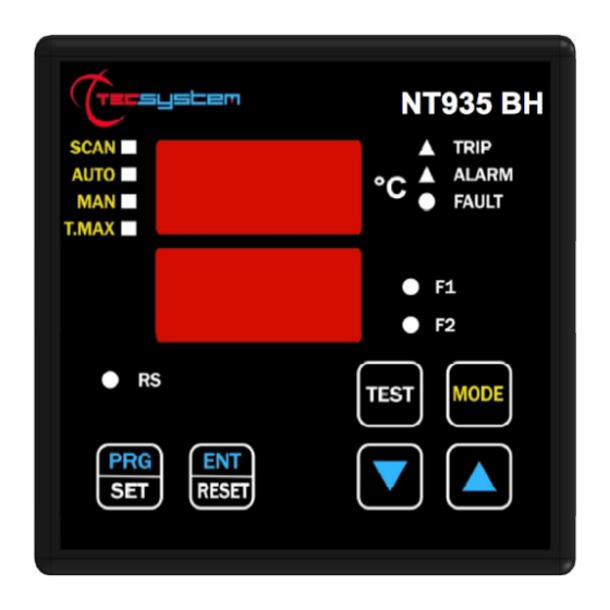
FRONT PANEL 1MN0189 REV. 0 3-digit temperature display Enter/Reset button Control unit series Programming/Setting key TRIP (red) LED Led/relay test key ALARM (yellow) LED Led (green) RS Modbus communication FAULT (red) LED 3-digit channel display FAN 1 TRBH signalling (yellow) T-max mode selection (red) LED FAN 2 (yellow) LED Man mode selection (yellow) LED... -
Page 9: Display
We suggest carrying out the control unit LED test regularly. For this operation, press the TEST key briefly; all the displays turn on for 2 seconds. If one of the LEDS does not work, please return the control unit to TECSYSTEM for repair. ALARM RELAY TEST This function allows you to carry out a test of the relay operation without having to use further devices. -
Page 10: Assembly
ASSEMBLY Drill a hole in the panel sheet with dimensions of 92 x 92 mm. 1MN0007 REV. 0 Control unit Panel hole dimensions (+0.8 mm tolerance) Identification label Secure the appliance firmly by means of the supplied fixing blocks. 1MN0008 REV. 0 Control unit Locking screws Fixing blocks... -
Page 11: Electrical Connections
NOTE: all the useful information on the TRBH ELECTRICAL CONNECTIONS system's electrical connections is available in the TRBH SYSTEM manual. NT935BH-D 1MN0189 REV.0 Pt100 sensors (white-red-red) Relay (FAN2) Power supply 85-260Vac-cc 50/60Hz. 5) FAN1 BLDC output (Control Box connection) Relays (ALARM-TRIP-FAULT) -
Page 12: Power Supply
To protect the control unit against line overvoltages, the PT-73-220 electronic arrester, designed by TECSYSTEM S.r.l. for this specific purpose, is recommended. Alternatively, it is advisable to use 110 V AC supply voltages or, even better, 110 If an existing control unit must be replaced with a new one, to guarantee its correct and safe operation, the sensor/relay/supply connecting terminals must be replaced with the new terminals supplied. -
Page 13: Programming
PROGRAMMING NT935BH D PITCH PRESS EFFECT PRESS NOTES Press and hold the PRG button until the display shows SET PRG Select PRG SET to proceed with programming or PRG 1 PRG 1 default data to load the default values The ALARM threshold for (CH 1-2-3) is displayed. Default 90°C Set the desired threshold, the Alarm LED flashes The TRIP threshold for (CH 1-2-3) appears and the Trip... - Page 14 The display shows OFF (CH4) Default 35°C the FAN2 LED flashes Set the desired threshold FAN2 OFF HFN (NO) is displayed Fan cyclic test for 5 min. every “n” hours The FAN1-FAN2 LEDs flash Default NO = function Set the desired number of hours disabled Fault for quick temperature FCD (NO) is displayed...
-
Page 15: Programming Notes
Pt100 sensors c) damage to the Pt100 inputs of the control unit. TECSYSTEM S.r.l. has designed its own special cable to transfer the measurement signals, CEI-compliant, with all the protection requirements provided for mod. CT-ES... -
Page 16: Temperature Sensor Diagnostics
CAL message display: the indication appears when the measurement circuit is damaged. The temperature values displayed might be incorrect. Return the control unit to TECSYSTEM for repairs. VOTING FUNCTION The voting function derives from the redundancy concept that consists in duplicating the components of a system to increase their reliability. -
Page 17: Cooling Fan Control
The fault signal BH Err involves the switching of the FAULT contact of the control unit. The NT935BH-D model, through the Modbus Mapping, also is used to monitor the speed (rpm) set by the control unit and the following failure cases for the single motor: •... -
Page 18: Fan Test
36 to 41 on page 11. The serial communication of the temperature control monitoring unit is only active when the NT935BH-D is in temperature control mode in one of the intended modes (Scan, Auto, Man and T.Max). -
Page 19: Data Packet
Trip thresholds and that the Fan-on thresholds must be higher than the Fan-off thresholds. If these thresholds are set incorrectly, the control unit NT935BH-D will not proceed with the programming and storage of data and therefore in subsequent readings the data from the previous schedule will be read After having sent a request for writing the control unit will take a time of about 1 '' to store the data in eeprom, during the step of storing the module ModBus will not be able to process additional requests. -
Page 20: Error Codes
In the case in which all the fans are turned off (FAN1, FAN2 and INT) the test of the relay will not take place. UNACCEPTABLE DATA There are some programmings that are not acceptable as they are not foreseen by the NT935BH-D instrument; such data will be discarded without producing any error message (EXCEPTION CODE). -
Page 21: Modbus Mapping Table
MODBUS MAPPING TABLE HEADER (Information and commands): R: read Address Data HI Data LO W:write (10) RW: read/write Model – MSD (ASCII) Model - 3° Digit (ASCII) Model – LSD (ASCII) Model - 2° Digit (ASCII) Vers. Fw – MSD(ASCII) Space (20H) Vers. - Page 22 Address Modbus address 1÷255 0=2400 Modbus baud 1=4800 rate 2=9600 3=19200 4=38400 0=N-1 Parity Modbus parity bit None+1Stop 1=Even 2=Odd 3=N-2 None+2Stop See notes on Bars/Fans Structure page 27 TEMPERATURE FANs: R: read Address Data HI Data LO Notes 1 Notes 2 W: write (10)
- Page 23 2’compl. Ch3 temper. 1°C ÷ 240°C 2’compl. sign As (AL) alarm set point 1°C÷200°C (*) 2’compl. Ch3 temper. 1°C ÷ 240°C 2’compl. sign As (TRP) trip set point 1°C÷200°C (*) -10°C ÷ 240°C 2’compl. sign 2’compl. Ch4 temper. –48°C÷200°C (*) 0°C ÷...
- Page 24 CHANNELS 1÷4: Setting R: read Address LO Data HI Data LO Notes 1 Notes 2 W:write (10) RW: read/write Ch1 Setting See Notes CHx Ch2 Setting See Notes CHx Ch3 Setting See Notes CHx Ch4 Setting See Notes CHx CHANNELS 1÷4: Status R: read Address Data HI...
- Page 25 REGISTERS NOTES INFO various causes (READ) BIT 7 BIT 6 BIT 5 BIT 4 BIT 3 BIT 2 BIT 1 BIT 0 (*) RESET (R) has taken place COMMANDS (WRITE) BIT 7 BIT 6 BIT 5 BIT 4 BIT 3 BIT 2 BIT 1 BIT 0...
-
Page 26: Failsafe Function
BARS/FANS STRUCTURE BIT 7 BIT 6 BIT 5 BIT 4 BIT 3 BIT 2 BIT 1 Num. Bars 1;2 Num. Motors for bar 1; 2; 3 Bar programming TRBH Bit 5-4: 0 1=BAR1 Programming of motors TRBH Bit 0-1: 0 1 = M1 1 0=BAR1-2 1 0 = M1-M2 1 1 = M1-M2-M3... -
Page 27: Fcd Function
"Tecsystem s.r.l. General Sales Conditions", which can be consulted on the website www.tecsystem.it and/or in the stipulated purchase contract. The warranty is considered valid only when the product is damaged by causes attributable to TECSYSTEM srl, such as manufacturing or components defects. -
Page 28: Troubleshooting
B2 bar, TRBH SYSTEM manual. Check the operating status and connection of the motors installed The control unit signals BH ERR B1-2 on the B1-2 bars, TRBH SYSTEM manual. Contact the TECSYSTEM Technical Department if the problem persists. NT935BH... -
Page 29: Equipment Disposal
Returning of used electrical appliances: contact TECSYSTEM or the TECSYSTEM agent to receive information on correct disposal of the appliances. TECSYSTEM is aware of the impact its products have on the environment and asks its customers active support in the correct and environmentally-friendly disposal of its devices.
Need help?
Do you have a question about the NT935BH-D and is the answer not in the manual?
Questions and answers