TECSYSTEM NT538 Instruction Manual
Hide thumbs
Also See for NT538:
- Instruction manual (12 pages) ,
- Instruction manual (13 pages) ,
- Instruction manual (30 pages)
Table of Contents
Advertisement
Advertisement
Table of Contents

Related Manuals for TECSYSTEM NT538


Summary of Contents for TECSYSTEM NT538
- Page 1 INSTRUCTION MANUAL NT538 1MN0123 REV. 0 operates with ISO9001 certified quality system TECSYSTEM S.r.l. 20094 Corsico (MI) Tel.: +39-024581861 Fax: +39-0248600783 http://www.tecsystem.it R. 1.3 23/05/16 ENGLISH “Translations of the original instructions”...
-
Page 2: Table Of Contents
INTRODUCTION First of all we wish to thank you for choosing to use a TECSYSTEM product and recommend you read this instruction manual carefully: You will understand the use of the equipment and therefore be able to take advantage of all its functions. - Page 3 10) OUTPUT 4.20mA (only AD) ………………………………….. 11) Pt100 EXTENSION CABLE TECHNICAL SPECIFICATIONS — ………………………………….. 12) FCD FUNCTION ………………………………….. 13) WARRANTY CONDITIONS — ………………………………….. 14) TROUBLESHOOTING — ………………………………….. 15) EQUIPMENT DISPOSAL ………………………………….. 16) USEFUL CONTACTS — ………………………………….. 17) UL SPECIFICATION AND RATINGS NT538...
-
Page 4: Safety Requirements
FUNCTION To control the transformer correctly from a temperature point of view, enabling the VOTING function is allowed where the load distributed between the phases of the transformer is adequately balanced. TECHNICAL INFORMATION Mail: ufficiotecnico@tecsystem.it — tel: 02/4581861 NT538... - Page 5 2PL0364 or 2PL0363 (*) 1 RS4 485 terminal 3 p poles pitch 3.81 de: 2PL0366 (*) (*) onl ly for NT538 AD ATTE ENTION: always s install the de evice using the e terminals incl luded in the pa ack.
-
Page 6: Technical Specifications
TECHNICAL SPECIFICATIONS NT538 BASIC NT538 AD POWER SUPPLY 24-240 Vac-Vdc 24-240 Vac-Vdc Supply rated values 50/60HZ 50/60HZ 20-270 Vac-Vdc 20-270 Vac-Vdc Maximum and minimum supply values 50/60HZ 50/60HZ Vdc with reversible polarities ● ● INPUTS 8 inputs for RTD sensors, Pt100 type with 3 wires (max section 1.5mm²) ●... - Page 7 TECHNICAL SPECIFICATIONS NT538 BASIC NT538 AD TESTS AND PERFORMANCE ● ● Front polycarbonate IP65 ● ● Housing NORYL 94 _V0 ● ● Absorption 7,5VA ● ● Data memory 10 years minimum ● ● Digital linearity of sensor signal ● ●...
-
Page 8: Front Panel
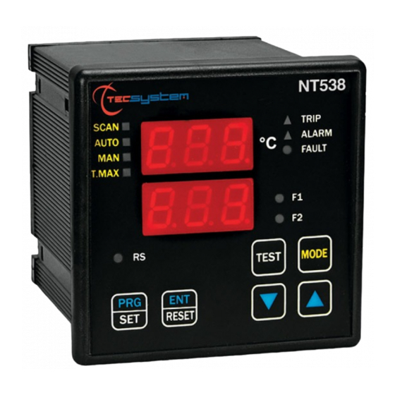
FAN 1 (yellow) LED T-max mode selection (red) LED FAN 2 (yellow) LED Man mode selection (yellow) LED Display mode selection key Auto mode selection (green) LED Fixing block Scan mode selection (yellow) LED UP key Fixing block DOWN key NT538... -
Page 9: Display
The first display is dedicated to temperatures. The second display to the monitored channel. When switching the device ON or following a reset, the display shows: the NT538 control unit model BAS (no options) or AD, VER "00" (firmware version) and temperature range of the unit. -
Page 10: Mounting
Drill a 92 x 92 mm hole in the panel sheet. 1MN0007 REV. 0 Control unit Panel hole dimensions (+0.8mm tolerance) Identification label Fix the unit securely with the blocks supplied. 1MN0008 REV. 0 Control unit Fixing screw Fixing block Crosshead screwdriver #1X100mm NT538... -
Page 11: Nt538 Basic Electrical Connections
CTRICAL L CONNE ECTIONS NT538 B BASIC MN0126 REV. t100 sensors ( (white-red-red Relays (FAN2-FAN 1-ALARM-TR RIP-FAULT) upply 24-240V Vac-dc 50/60H Note: re elay contact im mage in non-ala arm condition, with the excep ption of the FA AULT relay that... -
Page 12: Nt538 Ad Electrical Connections
CTRICAL L CONNE ECTIONS NT538 A 1MN0123 RE EV. 0 t100 sensors ( (white-red-red Relays (FAN2-FAN 1-ALARM-TR RIP-FAULT) upply 24-240V Vac-dc 50/60H Output t 4.20 mA Modbus RTU R RS485 output Note: re elay contact im mage in non-ala arm condition,... -
Page 13: Power Supply
POWER SUPPLY The NT538 control unit has UNIVERSAL power supply, i.e. it can be supplied by 24 to 240 Vac-Vdc, 50/60Hz irrespectively of polarity in Vdc (terminals 40-42). This is obtained thanks to the use of a tested power supply unit, newly designed and manufactured, that frees installers from worrying about the correct Vac and Vdc supply. -
Page 14: Programming
PROGRAMMING NT538 BASIC/AD STEP PRESS EFFECT PRESS NOTES Keep the PRG key pressed until the display shows PRG Press PRG to confirm entering programming mode YES = CH1 Enable CH1 is displayed CH1 activation NO = CH1 Disable Select YES or NO The ALARM threshold for (CH1) is displayed Default 90°... - Page 15 We recommend you check the unit's programming before starting the device. The default parameters set by TECSYSTEM might not match your requirements. Programming the device is the end user's responsibility, the settings of the alarm thresholds and the enabling of the functions described in this manual must be checked (by a specialized engineer) according to the application and features of the system the control unit is installed on.
-
Page 16: Programming Notes
(CH1- CH2-CH3-CH H4-CH5-CH6-CH H7-CH8) or on t the sensors the emselves. All "NT" s series control un nits have lineari ity of the sensor r signal, with a m maximum error of 1% of full sca ale value NT538... -
Page 17: Temperature Sensor Diagnostics
CAL message display: it appears when damage is found in the measurement circuit. The temperature values displayed might be incorrect. Return the control unit to TECSYSTEM for repairs. VOTING FUNCTION The voting function is derived from the concept of redundancy which consists of the duplication of components of a system with the intention of increasing reliability. -
Page 18: Programmed Data Diagnostics
(programmed parameter display) and modified in PRG (programming) mode. COOLING FAN CONTROL The unit NT538 has two contacts FAN (FAN1 and FAN2), if properly programmed, can control ON-OFF of fans for cooling system checked. The high flexibility of the NT538 allows you to select, for each channel, an operation mode for contact management of FAN1 and FAN2. -
Page 19: Rs485 Modbus (Only Ad)
The NT538 AD control unit is in communication with the network only when it is in temperature reading mode, while it is inactive when in the following modes: display, programming and relay test. -
Page 20: Function Code
If WRITE data must always respect the rule T_trip> T_alarm and FAN_ON> FAN_OFF. In case you try to set these thresholds incorrectly, the control unit NT538 will not proceed with the programming and storage of data, therefore in subsequent readings will read the data from the previous schedule. -
Page 21: Error Codes
Note. If the value of Voting is higher than the max value expected for the model in question, it will be set equal to "0", that is NO_VOTING. POLLING FREQUENCY We recommend polling frequencies equal to or greater than 1 second are adopted. More frequent polling can overload the system without any benefit whatsoever. NT538... -
Page 22: Modbus Mapping Table
HFN (Fan test) 0=No test 1÷200h temperature 0=No FCD increment 1÷30°/sec Voting 0=No Voting 1-2-3 CPU Setting See Note CPU Error See Note See Note Relays Status reference 0=hot 420 mA channel channel for 4.20 1÷8= ch1÷8 9 =scan NT538... - Page 23 1°C÷200°C (*) 2’compl. Ch2 temper. 1°C ÷ 240°C 2’compl. sign trip set point 1°C÷200°C (*) (TRP) –10°C ÷ 240°C 2’compl. sign 2’compl. Ch3 temper. –48°C ÷200°C (*) 0°C ÷ 240°C 2’compl. sign 2’compl. Ch3 max temperat. 0°C÷200°C (*) NT538...
- Page 24 2’compl. Ch8 max temperat. –48°C ÷200°C (*) 2’compl. Ch8 temper. 0°C ÷ 240°C 2’compl. sign As (AL) alarm set point 0°C÷200°C (*) 2’compl. Ch8 temper. 1°C ÷ 240°C 2’compl. sign trip set point 1°C÷200°C (*) (TRP) (*) for version –40°C ÷ +200°C NT538...
- Page 25 See Note CHx story Ch3 statu See Note CHx story Ch4 statu See Note CHx story Ch5 statu See Note CHx story Ch6 statu See Note CHx story Ch7 statu See Note CHx story Ch8 statu See Note CHx NT538...
- Page 26 BIT 4 BIT 3 BIT 2 BIT 1 BIT 0 PT ERROR FCD Fault CPU SETTING BIT 7 BIT 6 BIT 5 BIT 4 BIT 3 BIT 2 BIT 1 BIT 0 Failsafe fault Failsafe Failsafe trip (always=1) alarm NT538...
-
Page 27: Fail Safe Function
FAIL SAFE FUNCTION The NT538 AD has n.o selection (contact open ) / n.c (normally closed contact) for alarm and trip relays, programming steps 26 to 29 page 15. The selection of the setting YES/NO introduces functions Fail Safe and No Fail Safe. -
Page 28: Pt100 Extension Cable Technical Specifications
FCD function from activating during motor startup, or where the ΔT/sec. increase varies quickly. (*) The ΔT value shows the temperature range for each second. NOTE: you should not enable the FCD function with active VOTING. NT538... -
Page 29: Warranty Conditions
The w warranty is cons sidered valid on ly when the pro oduct is damag ed by causes a attributable to T TECSYSTEM sr rl, such as manuf facturing or com mponents defect The w warranty is inval id if the Produc... -
Page 30: Useful Contacts
USEFUL CONTACTS TECHNICAL INFORMATION: ufficiotecnico@tecsystem.it SALES INFORMATION: info@tecsystem.it UL SPECIFICATION AND RATINGS CABLE SPECIFICATION Dimension for main circuit 18AWG, working temperature over 105°C MASS OF THE EQUIPMENT 0,45 Kg INPUT SUPPLY 24 – 240 Vac / Vdc (±10%), 50/60 Hz, 7,5VA max...
Need help?
Do you have a question about the NT538 and is the answer not in the manual?
Questions and answers